
Design of Magnetron for Beamforming †

Abstract
1. Introduction
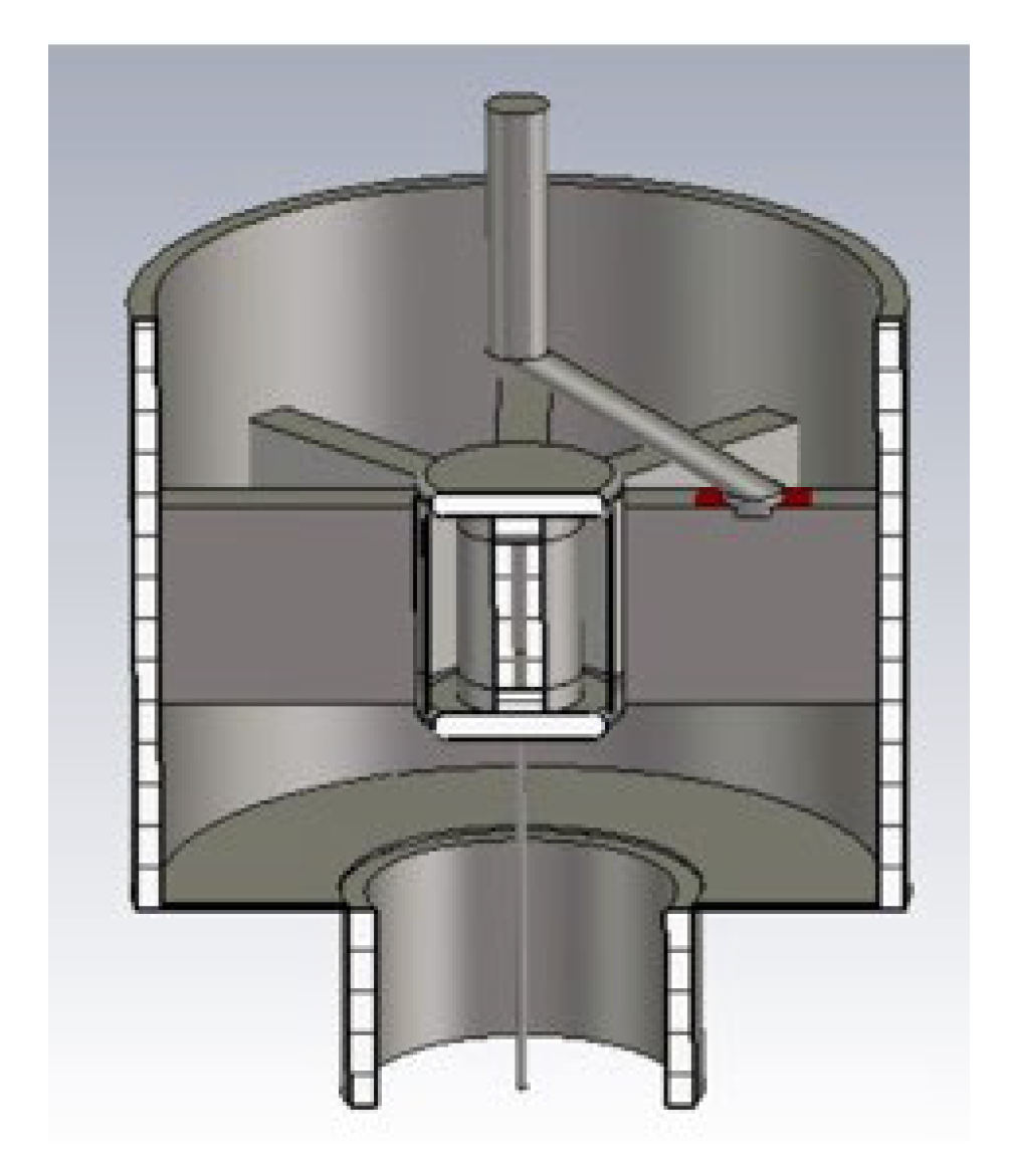
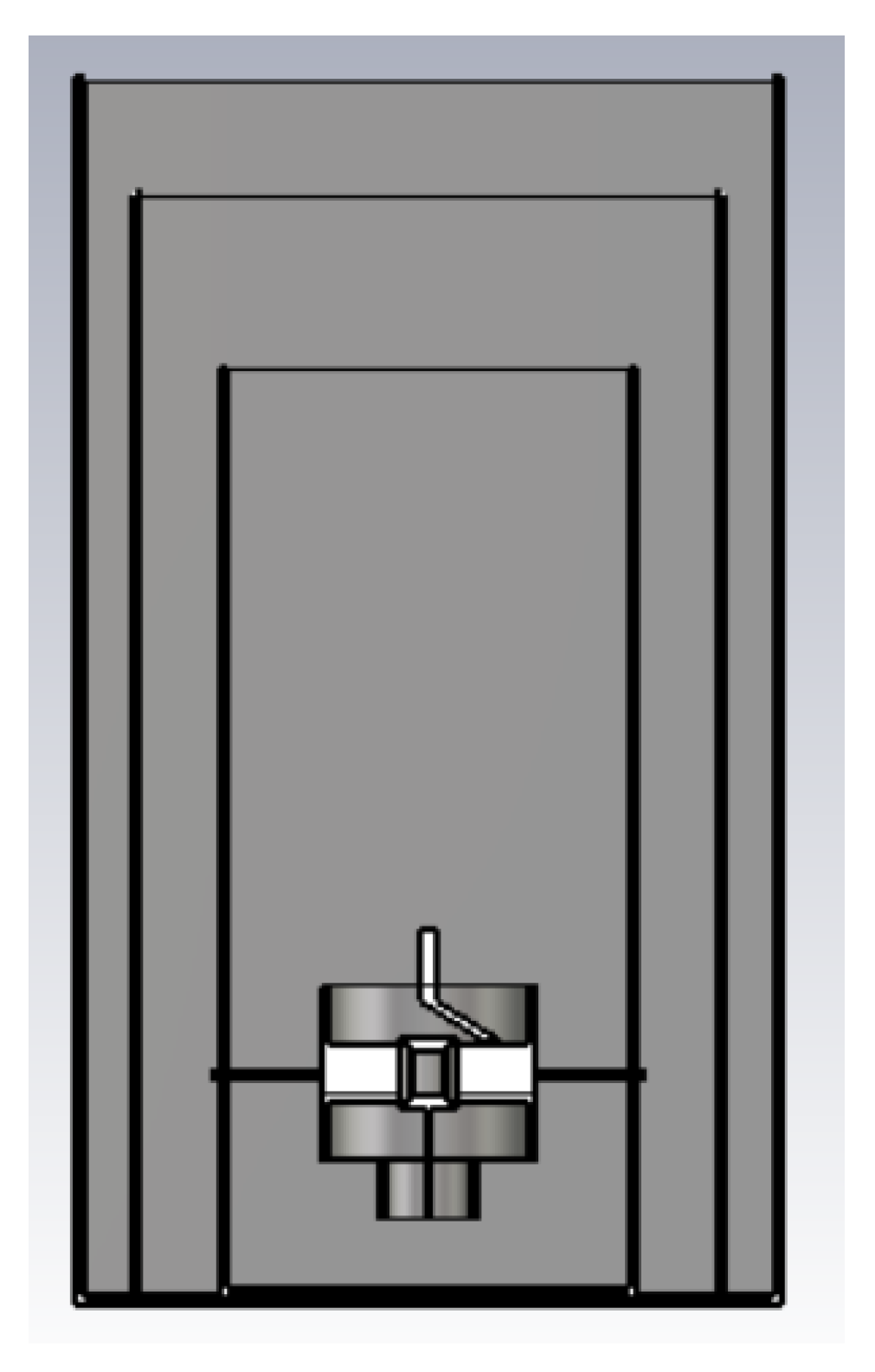
2. Magnetron Design
Magnetron Design Process
3. Simulations
3.1. Cold Simulation
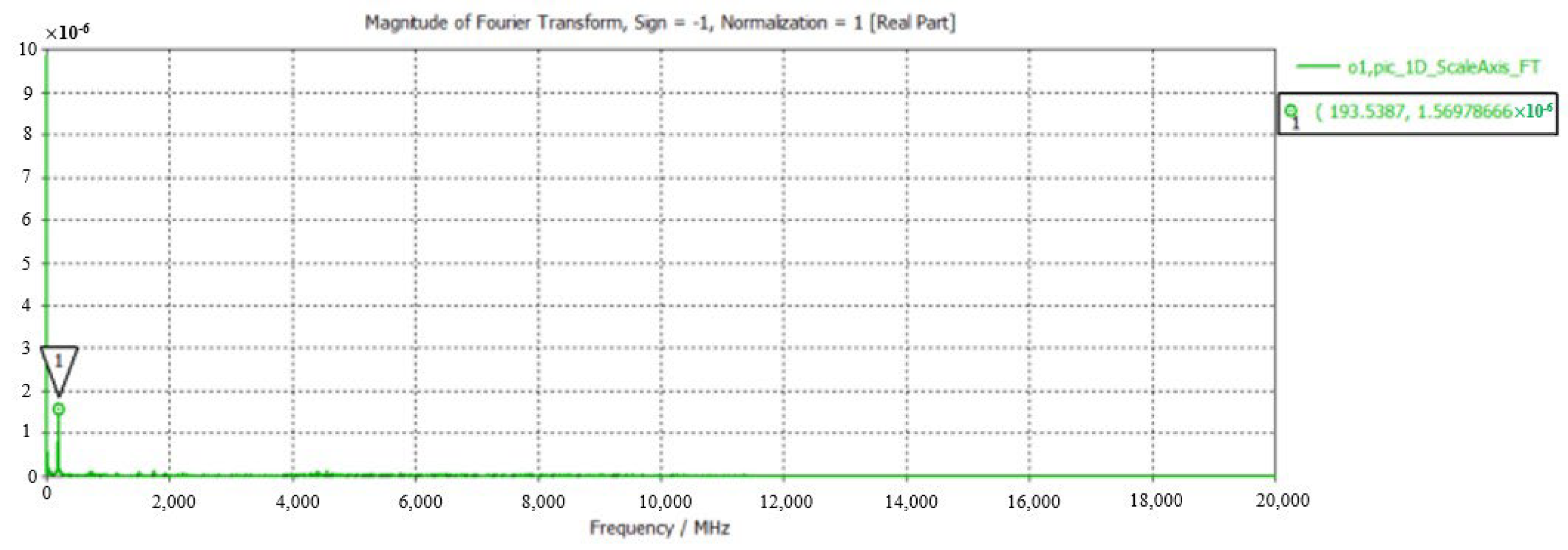
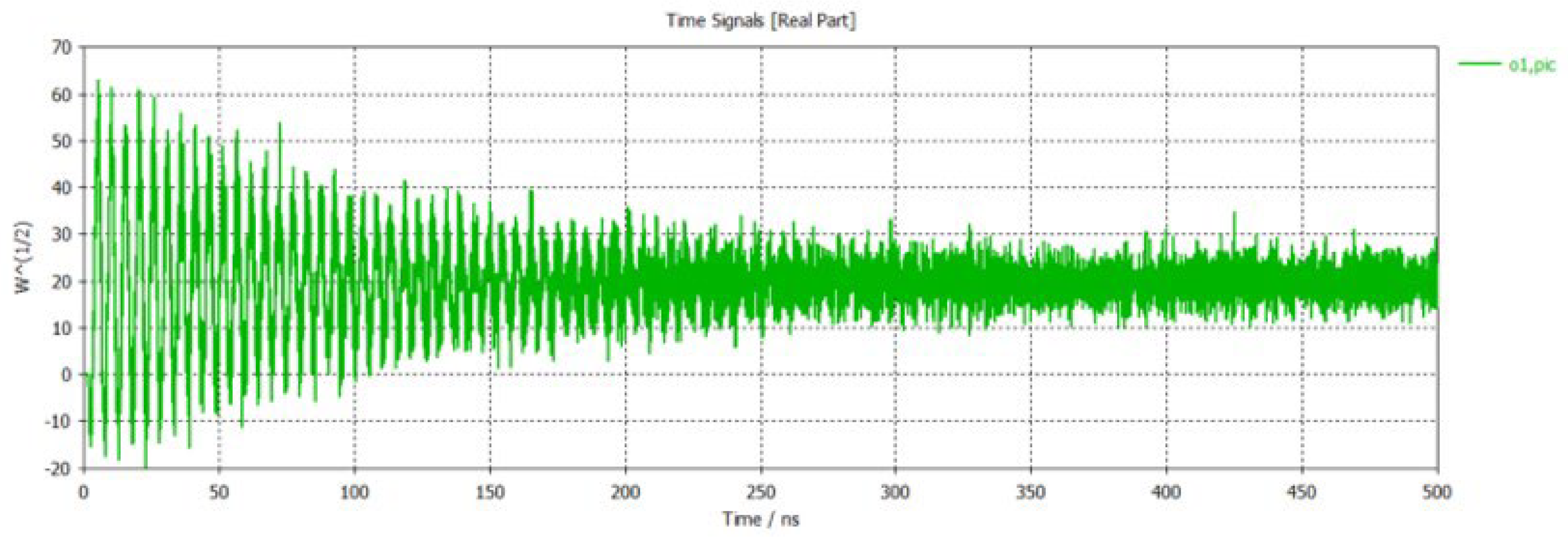
3.2. Hot Simulation
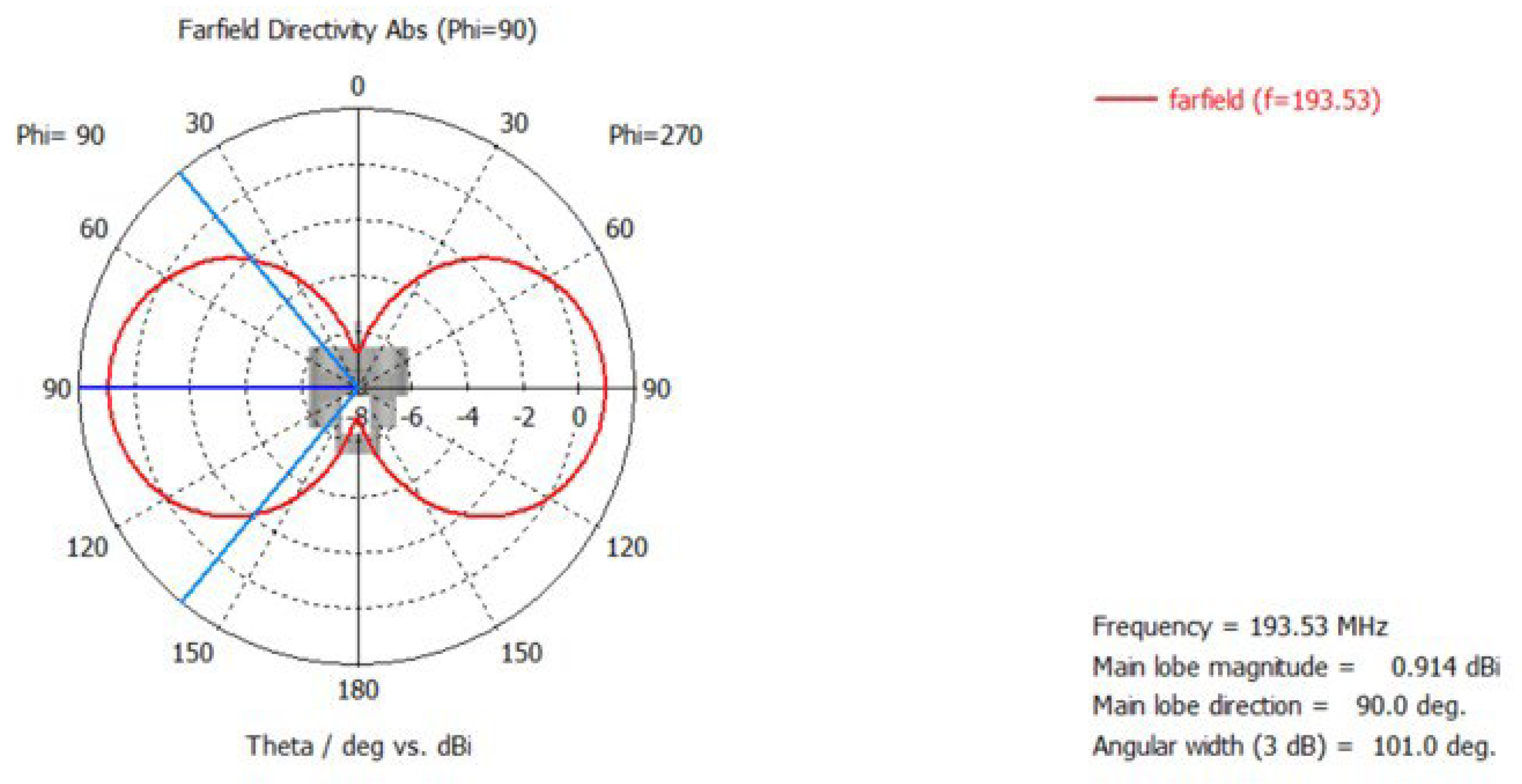
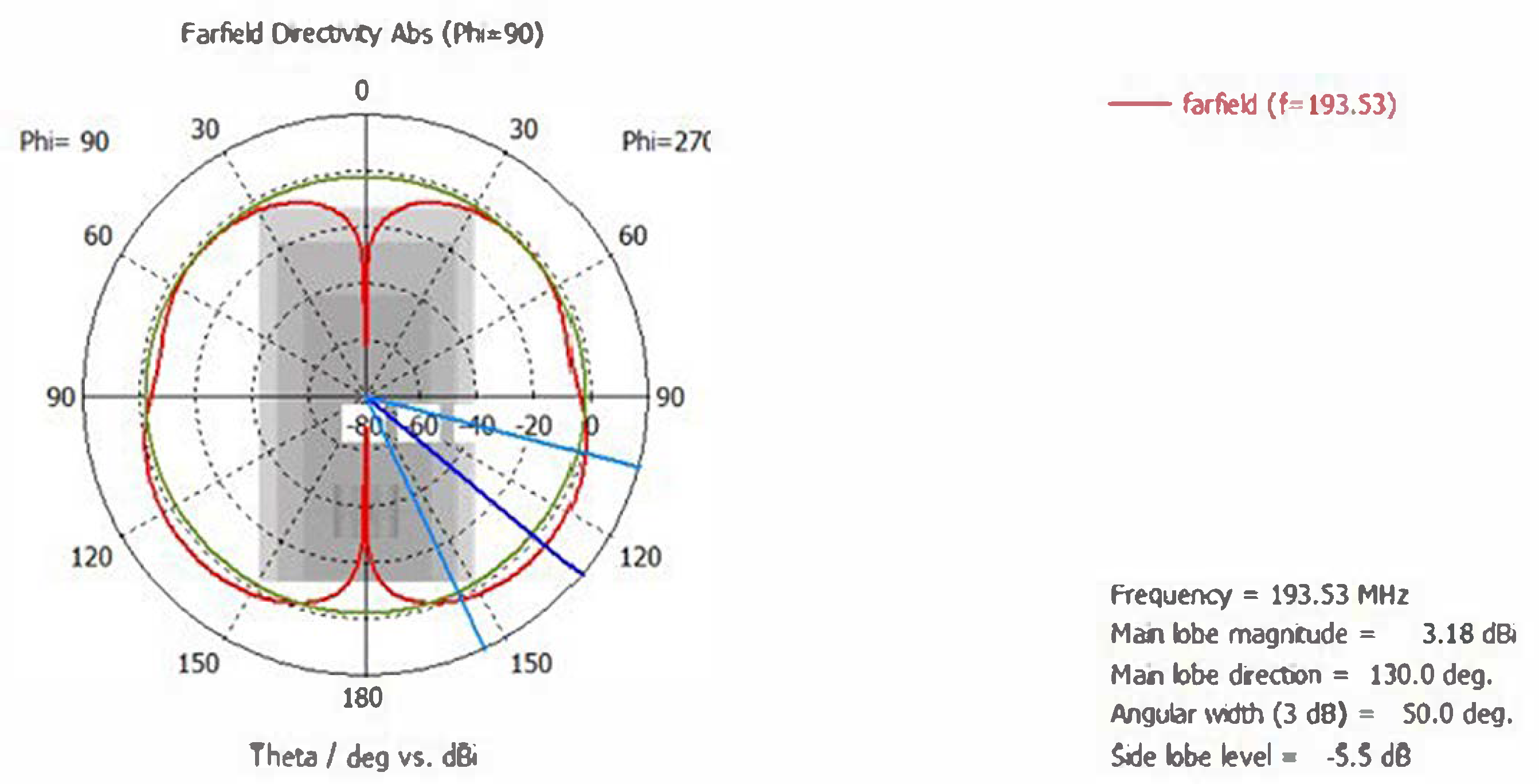
4. Radiation Pattern Simulation
5. Conclusions
Author Contributions
Funding
Institutional Review Board Statement
Informed Consent Statement
Data Availability Statement
Conflicts of Interest
References
- Khatoon, S.; Yadav, R.P.; Jain, A. Design and Simulation of 8-cavity hole-slot type magnetron in CST. In Proceedings of the 2nd International Conference on Electronics, Materials Engineering & Nano-Technology (IEMENTech), Kolkata, India, 4–5 May 2018; pp. 1–5. [Google Scholar]
- Kim, J.-I.; Won, J.-H.; Ha, H.-J.; Shon, J.-C.; Park, G.-S. Three-Dimensional Particle-in-Cell Simulation of 10-Vane Strapped Magnetron Oscillator. IEEE Trans. Plasma Sci. 2004, 32, 2099–2104. [Google Scholar] [CrossRef]
- Kim, D.-H.; Jung, S.-S.; Kim, J.-I.; Jeon, S.-G. Three-Dimensional Particle-in-Cell Simulation on a Magnetron Oscillator with Mismatched Loads. J. Korean Phys. Soc. 2009, 54, 1675–1679. [Google Scholar] [CrossRef]
- Collins, G.B. Microwave Magnetrons (MIT Radiation Laboratory Series); McGraw-Hill: New York, NY, USA, 1948. [Google Scholar]
- Vyas, S.K.; Maurya, S.; Verma, R.K.; Singh, V.P. Synthesis and simulation studies of a 10-kW 2.45-GHz CW magnetron. IEEE Trans. Plasma Sci. 2015, 43, 3615–3619. [Google Scholar] [CrossRef]
- Vyas, S.K. Synthesis and analysis of strap & vane resonator of an efficient 10 kW CW Magnetron—A Design Approach. In The Technical Writer’s Handbook; Young, M., Ed.; University Science: Mill Valley, CA, USA, 1989. [Google Scholar]
- Vyas, S.K.; Maurya, S.; Singh, V.P. Electromagnetic and Particle-in-Cell Simulation Studies of a High Power Strap and Vane CW Magnetron. IEEE Trans. Plasma Sci. 2014, 42, 3373–3379. [Google Scholar] [CrossRef]


| Parameter | Value | Unit |
|---|---|---|
| Frequency | 193 | MHz |
| Anode voltage | 30 | kV |
| B | 0.18 | Tesla |
| Anode radius | 2 | cm |
| Anode height | 4 | cm |
| Cathode outer diameter | 0.9 | cm |
| Cathode inner diameter | 0.8 | cm |
| Cell height | 12 | cm |
| End cap radius | 2.5 | cm |
| End cap height | 0.5 | cm |
| Vane height | 4 | cm |
| Vane width | 1 | cm |
| Vane length | 5 | cm |
| Simulated Structure | Directivity | HPBW |
|---|---|---|
| Individual magnetron | 0.941 dBi | 101 deg |
| Magnetron with outer box | 3.18 dBi | 50 deg |
Disclaimer/Publisher’s Note: The statements, opinions and data contained in all publications are solely those of the individual author(s) and contributor(s) and not of MDPI and/or the editor(s). MDPI and/or the editor(s) disclaim responsibility for any injury to people or property resulting from any ideas, methods, instructions or products referred to in the content. |
© 2025 by the authors. Licensee MDPI, Basel, Switzerland. This article is an open access article distributed under the terms and conditions of the Creative Commons Attribution (CC BY) license (https://creativecommons.org/licenses/by/4.0/).
Share and Cite
Su, C.-H.; Ku, M.-X. Design of Magnetron for Beamforming. Eng. Proc. 2025, 92, 89. https://doi.org/10.3390/engproc2025092089
Su C-H, Ku M-X. Design of Magnetron for Beamforming. Engineering Proceedings. 2025; 92(1):89. https://doi.org/10.3390/engproc2025092089
Chicago/Turabian StyleSu, Chun-Hsi, and Meng-Xun Ku. 2025. "Design of Magnetron for Beamforming" Engineering Proceedings 92, no. 1: 89. https://doi.org/10.3390/engproc2025092089
APA StyleSu, C.-H., & Ku, M.-X. (2025). Design of Magnetron for Beamforming. Engineering Proceedings, 92(1), 89. https://doi.org/10.3390/engproc2025092089