Abstract
As network demands increase, encryption becomes increasingly important. Visual secret sharing (VSS) encrypts a secret image into multiple images (called shares) and then superimposes these shares so that the original image can be directly identified by humans. In traditional VSS, black represents 1 and white represents 0. Therefore, traditional VSS decryption methods are viewed as logical OR operations. In 1997, the VSS scheme based on the polarization of the light wave was proposed. It utilizes the fact that light passes through a unidirectional polarizer but cannot pass through two mutually perpendicular polarizers. This scheme is relevant to a logical XOR operation in decryption. However, this scheme does not explain the situation when more than two shares are decrypted. Therefore, a new (t, n)-threshold VSS scheme based on polarization (called (t, n)-threshold P-VSS) was proposed to solve the above problem. In that (t, n)-threshold P-VSS scheme, four types of polarizers were used to design the scheme. In this study, we propose three (t, n)-threshold P-VSS schemes, each using only two or three types of polarizers to effectively reduce the proportion of black pixels in the shares compared with previous work. Experimental results and theoretical analysis prove the safety and effectiveness of these schemes.
1. Introduction
Visual secret sharing (VSS) was first proposed by Naor and Shamir in 1994 [1] to encrypt secret images into multiple shared images, known as shares. The decryption process involves directly stacking these shares without computation. The VSS method is typically described as a (t, n)-threshold scheme, where 2 ≤ t ≤ n, meaning that a secret image is divided into n shares, and any group of at least t shares can be stacked to reconstruct the original image ((t, n)-VSS). However, pixel expansion is a challenge in VSS. Therefore, many researchers have explored its alternatives, such as the random grid-based visual cryptography (RG-based VC) method [2]. Initially, RG-based VC only solved (2, 2)-VSS. Its application expanded to larger (k, n)-VSS schemes, where 2 ≤ k ≤ n [3,4,5,6], and was even generalized for arbitrary values of k and n [7,8,9]. Subsequently, there have been many related studies [10,11,12,13,14].
Light polarization was first used for VSS by Biham and Itzkovitz [15]. They introduced a novel VSS scheme based on light polarization. Polarization is a property of light waves. Polarizers filter light oscillating in a single direction. Light passes through one polarizer in a single direction but is blocked by two polarizers stacked perpendicularly. In other words, light propagates in the direction of the polarization, and when the polarizers are stacked orthogonally, no light passes through, resulting in a black pixel. Conversely, when the polarizers are aligned, light passes through them, showing a white pixel. Therefore, researchers generate light waves oriented perpendicular to each other using two types of polarizers. This superposition produces white (transparent) or black (blocked) outcomes. The vertical polarizer is typically assigned 1, while the horizontal polarizer is assigned 0. The result of stacking two polarizers corresponds to the XOR logic: polarizers with the same orientation result in a white pixel (0), while differing orientations result in a black pixel (1). Yamamoto et al. demonstrated polarization decoding by stacking thin films [16].
When stacking more than two polarizers, the XOR concept leads to errors. For instance, if two vertical (1) polarizers and one horizontal (0) polarizer are stacked, the XOR operation is supposed to make a white pixel (0), but in reality, a black pixel appears (0). Therefore, Huang and Juan introduced a new method for interpreting VSS based on light polarization, called P-VSS [17]. They proposed a (t, n)-threshold P-VSS scheme (called (t, n)-threshold P-VSS for short) using four different types of polarizers. When t > 2, each share contains (n − 1)/4n, which is approximately 25%, of the black pixels in their scheme. In applications, it is expected that the shares will not have too many black pixels. They may even have no black pixels at all. In addition, using fewer polarizers reduces costs.
In this study, we designed a new (t, n)-threshold P-VSS scheme using fewer polarizers to produce shares with fewer black pixels or even completely white shares. We proposed three (t, n)-threshold P-VSS schemes, each using only two or three types of polarizers to effectively reduce the proportion of black pixels in the shares to as low as 0%.
This paper is organized as follows: Section 2 presents useful definitions and Huang and Juan’s (t, n)-threshold P-VSS scheme [17], and Section 3 describes the proposed improved schemes. The experimental results are shown in Section 4. An analysis of these schemes and a comparison with previous schemes are explained in Section 5, and the last section concludes this study.
2. Preliminary Studies
VSS based on light polarization and the related formula are first explored in this section to calculate the image restoration effect in a VSS scheme, contrast, as the measurement standard in this study. Since this paper mainly improves the scheme in [17] proposed in 2023, the (t, n)-threshold P-VSS scheme in Ref. [17] is briefly introduced next to facilitate comparison with our scheme later.
2.1. Definitions
The light transmittance (T(C)) is defined as the ratio of the number of transparent (white) pixels in image C to the total number of pixels in that image. By using transmittance, the contrast (α) is used to evaluate the visibility of the reconstructed image and the effectiveness of the VSS scheme in transmitting the secret information. Traditionally, contrast (α) is used to determine the visibility of reconstructed images and the ability of a VSS to reveal secret information [7]. Specifically, the transmittance in certain areas in the reconstructed image (C) is defined as T0 = T(C(S(0))), representing the light transmittance of the partial area in the reconstructed image (C) corresponding to the white area of the secret image (S). Similarly, T1 = T(C(S(1))) represents the light transmission of the partial area in the reconstructed image (C) corresponding to the black area of the secret image (S). Therefore, the contrast (α) of a reconstructed image (C) is defined as follows:
α = (T0 − T1)/(1 + T1)
Huang and Juan introduced the interpretation method of VSS based on light polarization, P-VSS [17]. We briefly introduce their main ideas and the definition of P-VSS as follows: There are four types of polarization used in their scheme, as shown in Figure 1. To represent polarization, an ordered pair (horizontal and vertical) is used. If a direction of polarization exists, it is expressed as 1, otherwise it is expressed as 0. Only the (1,1)-type polarizer appears black in visual since no light passes through the polarizer, while the others appear white in visual. Thus, the outcome of light passing through a polarizer of type (a, b) is analogous to the operation a × b, where × denotes a logical AND operation. When two polarizers are stacked, the interaction resembles performing an OR operation on two corresponding ordered binary pairs. Specifically, if light traverses a combination of two polarizers, types (a, b) and (c, d), the result behaves as though light passes through a polarizer of type (a ⨂ c, b ⨂ d), where ⨂ indicates a logical OR operation.
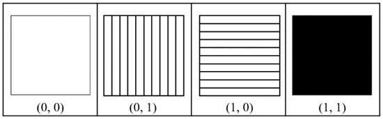
Figure 1.
Four types of polarizers.
2.2. Related Scheme
Two perfect (2, n)-threshold P-VSS and (t, n)-threshold P-VSS schemes were proposed in Ref. [17]. In their (2, n)-threshold P-VSS scheme, when any two shares are stacked, the secret image becomes identifiable, and when all shares are stacked, the recovered image is exactly the same as the secret image (in fact, it is enough to collect more than ⌊n/2⌋ shares [17]). See Ref. [17] for a detailed algorithm. For t > 2, the (t, n)-threshold P-VSS for encryption using four types of polarizers is as follows:
The main difference between these two algorithms is that g2, g3, …, gt−1 are randomly generated from {(1, 0), (1, 0)} or {(0, 0), (1, 0), (0, 1), (1, 1)}, and gt = s ⊕ g1 ⊕ g2 … ⊕ gt−1 has two or four possibilities. Therefore, the shares generated later will consist of two or four types of polarizers. Note that s ⊕ g = (a ⊕ c, b ⊕ d) for s = (a, b) and g = (c, d), where ⊕ represents a logical XOR operation.
3. New (t, n)-Threshold P-VSS Scheme
We modified Algorithm 1 from Ref. [17] by referring to the random grid idea proposed by Kafri and Keren in Ref. [2]. This means that the size of the reconstructed image was the same as that of the original secret image. When t > 2 and an even number, Algorithm 1 can be extended to Algorithm 2. Algorithm 2 only uses (1, 0)- and (0, 1)-type polarizers for encryption. When t > 2 and an odd number, Algorithm 1 is modified to Algorithms 3 and 4 using three different types of polarizers.
| Algorithm 1 [17] |
| Input: a w × h binary secret image (S) and the parameter (n). Output: n shares (G1, …, Gn). Step 1. For each position (i, j) ∈ {(i, j) | 1 ≤ i ≤ w, 1 ≤ j ≤ h}, repeat Steps 2–7. Step 2. If S[i, j] = 0, then s = (0, 0); else, s = (1, 1). Step 3. Randomly generate g1 as (0, 1) or (1, 0). Step 4. Randomly generate g2, g3, …, gt–1 as (0, 0), (1, 0), (0, 1), or (1, 1). Step 5. g2 = s ⊕ g1 ⊕ g2 ⊕ … ⊕ gt–1. Step 6. Set gt+1 = g1, gt+2 = g2, ···, g2t = gt, g2t+1 = g1, …. If (n mod t) = 0, gn = gt; else, gn = g(n mod t). Step 7. Randomly rearrange g1, g2, …, gn to G1[i, j], G2[i, j], …, Gn[i, j]. Step 8. Output the n shares (G1, G2, ⋯ Gn). |
| Algorithm 2 New (t, n) P-VSS scheme for even t values |
| Input: a w × h binary secret image (S) and the parameter (n). Output: n shares (G1, …, Gn). Step 1. For each pixel (S[i, j]) of the secret image (S), repeat Steps 2–6. Step 2. If S[i, j] = 0, then set s = (0, 0); else, set s = (1, 1). Step 3. For each g1, g2, g3, …, gt−1, randomly select one from (0, 1) or (1, 0) as its value. Step 4. Set gt = s ⊕ g1 ⊕ g2 ⊕ … ⊕ gt−1. Step 5. For i = t + 1 to n, if (i mod t) = 0, gi = gt; else, gi = g(i mod t). Step 6. After randomly rearranging g1, g2, …, gn, assign them to G1[i, j], G2[i, j], …, Gn[i, j] one by one. Step 7. Output G1, G2, ⋯ Gn (the n shares). |
In Algorithm 1, (0, 0)- and (1, 1)-type polarizers are used, while they are not used in Algorithm 2. Therefore, all shares in Algorithm 2 appear white. However, it is unavoidable to use (0, 0)- and (1, 1)-type polarizers in Algorithm 2 when t is odd. Table 1 provides an example where t is 3. It is not appropriate to convert (0, 0)- to (0, 1)-type polarizers or (1, 1)- to (1, 0)-type polarizers or vice versa. To solve this problem, we created Algorithm 3 with a (0, 0)-type polarizer and Algorithm 4 with a (1, 1)-type polarizer as an additional third type.
| Algorithm 3 New (t, n) P-VSS scheme for odd t values with (0, 0)-type polarizer |
| Input: a w × h binary secret image (S) and the parameter (n). Output: n shares (G1, …, Gn). Step 1. For each pixel (S[i, j]) of the secret image (S), repeat Steps 2–7. Step 2. If S[i, j] = 0, then set s = (0, 0); else, set s = (1, 1). Step 3. For each g1, g2, g3, …, gt−1, randomly select one from (0, 1) or (1, 0) as its value. Step 4. Set g′t = s ⊕ g1 ⊕ g2 ⊕ … ⊕ gt−1. Step 5. If g′t = (1, 1), randomly generate gt as (0, 1) or (1, 0). Step 6. For i = t + 1 to n, if (i mod t) = 0, gi = gt; else, gi = g(i mod t). Step 7. After randomly rearranging g1, g2, …, gn, assign them to G1[i, j], G2[i, j], …, Gn[i, j] one by one. Step 8. Output G1, G2, ⋯ Gn (the n shares). |

Table 1.
Algorithm 2 with t = 3.
| Algorithm 4 New (t, n) P-VSS scheme for odd t values with (1, 1)-type polarizer |
| Input: a w × h binary secret image (S) and the parameter (n). Output: n shares (G1, …, Gn). Step 1. For each pixel (S[i, j]) of the secret image (S), repeat Steps 2–7. Step 2. If S[i, j] = 0, then set s = (0, 0); else, set s = (1, 1). Step 3. For each g1, g2, g3, …, gt−1, randomly select one from (0, 1) or (1, 0) as its value. Step 4. Set g′t = s ⊕ g1 ⊕ g2 ⊕ … ⊕ gt−1. Step 5. If g′t = (0, 0), randomly generate gt as (0, 1) or (1, 0). Step 6. For i = t + 1 to n, if (i mod t) = 0, gi = gt; else, gi = g(i mod t). Step 7. After randomly rearranging g1, g2, …, gn, assign them to G1[i, j], G2[i, j], …, Gn[i, j] one by one. Step 8. Output G1, G2, ⋯ Gn (the n shares). |
4. Experimental Results
Three experiments were conducted to show the situations of (3, 5)- and (4, 5)-threshold P-VSS schemes encrypted using Algorithms 2–4. The secret images measured 512 × 512 pixels (Figure 2).
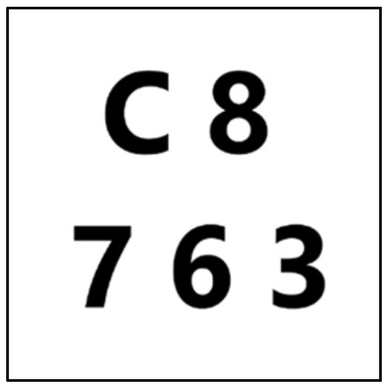
Figure 2.
Secret image.
4.1. New (4, 5)-Threshold P-VSS Scheme
Since only polarizers of types (1, 0) and (0, 1) were used to encrypt the secret images when t = 4 (an even number), the resulting shares appeared entirely white, without any black pixels. Figure 3 illustrates the outcome of stacking these shares, while Table 2 presents the light transmission and contrast. In Table 2, Table 3 and Table 4, k represents the number of shares stacked.
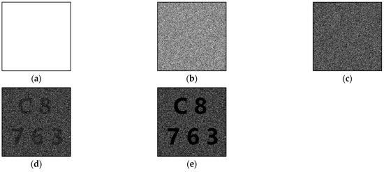
Figure 3.
Experimental results of proposed new (4, 5)-threshold P-VSS scheme: (a) any one share, (b) stacking any two shares, (c) stacking any three shares, (d) stacking any four shares, and (e) stacking all five shares.
Table 2.
The experimental results of the proposed new (4, 5)-threshold P-VSS scheme.
4.2. New (3, 5)-Threshold P-VSS Scheme with (0, 0)-Type Polarizer
We transformed the (1, 1)-type polarizer into (1, 0)- and (0, 1)-type polarizers and reserved a (0, 0)-type polarizer in Algorithm 3. All shares appeared white since the (1, 1)-type polarizer did not exist. Figure 4 shows the restoration results of stacking different numbers of shares, and Table 3 shows the light transmission and contrast values.
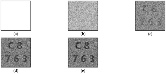
Figure 4.
Experimental results of proposed new (3, 5)-threshold P-VSS scheme with (0, 0)-type polarizer: (a) any one share, (b) stacking any two shares, (c) stacking any three shares, (d) stacking any four shares, and (e) stacking all shares.
Figure 4.
Experimental results of proposed new (3, 5)-threshold P-VSS scheme with (0, 0)-type polarizer: (a) any one share, (b) stacking any two shares, (c) stacking any three shares, (d) stacking any four shares, and (e) stacking all shares.

Table 3.
The experimental results of the proposed new (3, 5)-threshold P-VSS scheme with a (0, 0)-type polarizer.
Table 3.
The experimental results of the proposed new (3, 5)-threshold P-VSS scheme with a (0, 0)-type polarizer.
| k = 1 | k = 2 | k = 3 | k = 4 | k = 5 | |
|---|---|---|---|---|---|
| T0 | 1 | 0.699822 | 0.504241 | 0.499704 | 0.499704 |
| T1 | 1 | 0.700421 | 0.4504241 | 0.300634 | 0.251052 |
| α | 0 | −0.00035 | 0.0684709 | 0.153056 | 0.198754 |
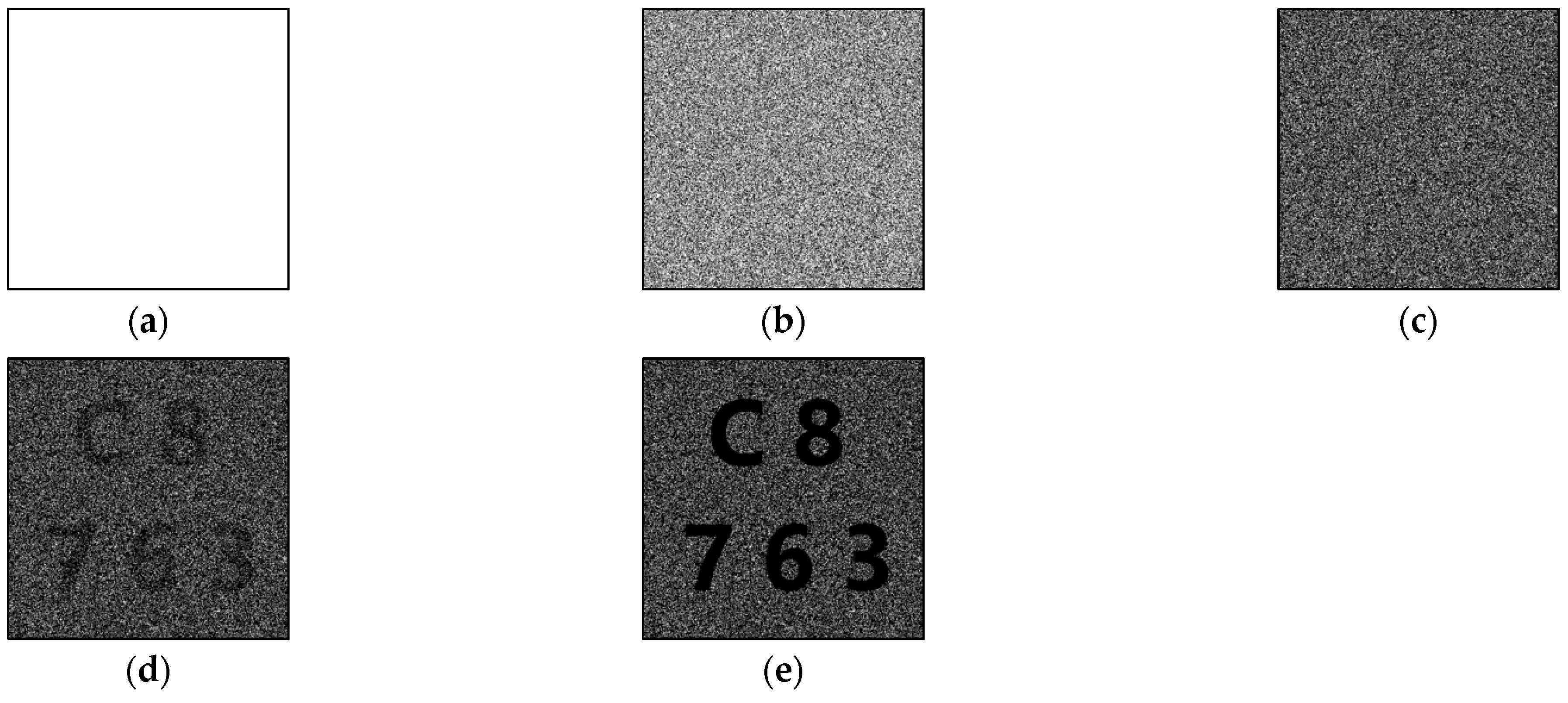
4.3. New (3, 5)-Threshold P-VSS Scheme with (1, 1)-Type Polarizer
On the other hand, we transformed the (0, 0)-type polarizer into (1, 0)- and (0, 1)-type polarizers and reserved the (1, 1)-type polarizer in Algorithm 4. Some black pixels were shown in the shares because the (1, 1)-type polarizer was assigned to the shares. Figure 5 shows the restoration results of stacking different numbers of shares in this experiment, and Table 4 shows the light transmission and contrast values.

Figure 5.
Experimental results of proposed new (3, 5)-threshold P-VSS scheme with (1, 1)-type polarizer: (a) any one share, (b) stacking any two shares, (c) stacking any three shares, (d) stacking any four shares, and (e) stacking all shares.
Figure 5.
Experimental results of proposed new (3, 5)-threshold P-VSS scheme with (1, 1)-type polarizer: (a) any one share, (b) stacking any two shares, (c) stacking any three shares, (d) stacking any four shares, and (e) stacking all shares.
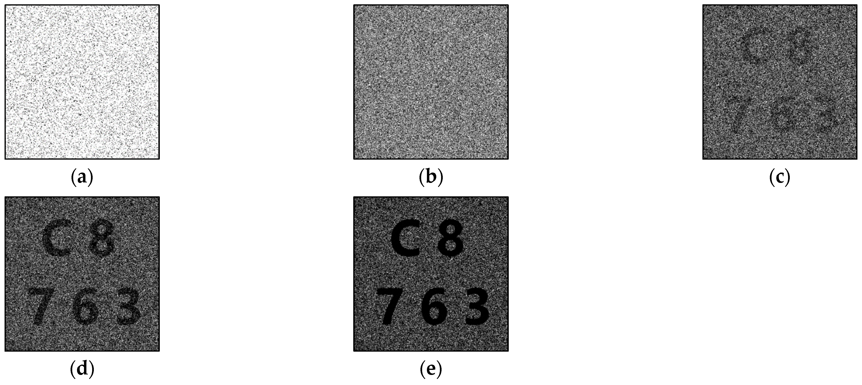
Table 4.
The experimental results of the proposed new (3, 5)-threshold P-VSS scheme with a (1, 1)-type polarizer.
Table 4.
The experimental results of the proposed new (3, 5)-threshold P-VSS scheme with a (1, 1)-type polarizer.
| k = 1 | k = 2 | k = 3 | k = 4 | k = 5 | |
|---|---|---|---|---|---|
| T0 | 0.899515 | 0.498276 | 0.347899 | 0.298007 | 0.248115 |
| T1 | 0.899489 | 0.500510 | 0.250765 | 0.100511 | 0 |
| α | 0.000015 | −0.001482 | 0.077666 | 0.179464 | 0.248115 |
5. Discussion
We evaluated the proposed schemes and compared their outcomes with those from related studies.
5.1. New (t, n)-Threshold P-VSS Scheme for Even t Values
When there is t − 1 (0, 1) or (1, 0) in a ⊕ operation, the result must be (0, 1) or (1, 0) because t − 1 is odd. In fact, if there is an odd number of (0, 1), it means there is an even number of (1, 0) and the result must be (0, 1), and vice versa. Hence, the result of a t − 1 polarizer and a secret pixel ((0, 0) or (1, 1)) with a ⊕ operation must be (0, 1) or (1, 0). The results when t − 1 = 3 are shown in Table 5 and Table 6. Therefore, when t shares are stacked,
T0 = 22−t, T1 = 0, α = 22−t.
Table 5.
Results of ⊕ operation on any three polarizers.
Table 6.
Results of ⊕ operation on any odd number of t − 1 polarizers and secret pixel (s).
5.2. New (t, n)-Threshold P-VSS Scheme for Odd t Values with (0, 0)-Type Polarizer
When there is an even t − 1 (0, 1) or (1, 0) during a ⊕ operation, the result must be (1, 1) or (0, 0) because t − 1 is even. If there is an odd number of (0, 1), there is also an odd number of (1, 0) and the result must be (1, 1), and vice versa. Hence, the result of a t − 1 polarizer and a secret pixel ((0, 0) or (1, 1)) with a ⊕ operation must be (0, 0) or (1, 1). Table 1 shows an example for t = 3. In order to reduce the usage of (0, 0)- and (1, 1)-type polarizers, we convert them into (0, 1)- and (1, 0)-type polarizers. If both of them are converted, the restored images are meaningless no matter how many shares are stacked. Therefore, one of (0, 0) or (1, 1) must be reserved.
Here, we convert (1, 1) into a (1, 0)- or (0, 1)-type polarizer. The (1, 1)-type polarizer only appears in two cases. One is when the secret pixel is white with odd (0, 1) (and odd (1, 0)) in g1, g2, g3, …, gt−1. The other is when the secret pixel is black with even (0, 1) (and even (1, 0)) in g1, g2, g3, …, gt−1.
As a result, the black pixels cannot be restored completely, as shown in Table 7. With n shares stacked,
Table 7.
Results of ⊕ operation on any odd number of t polarizers and secret pixel (s) with (0, 0)-type polarizer.
5.3. New (t, n)-Threshold P-VSS Scheme for Odd t Values with (1, 1)-Type Polarizer
On the other hand, we convert the (0, 0)-type polarizer into (1, 0)- and (0, 1)-type polarizers and reserve the (1, 1)-type polarizer. The (0, 0)-type polarizer only appears in two cases. One is when the secret pixel is black with odd (0, 1) (and odd (1, 0)) in g1, g2, g3, …, gt−1. The other is when the secret pixel is white with even (0, 1) (and even (1, 0)) in g1, g2, g3, …, gt−1.
In this way, the black pixels are restored completely, but the light transmission of the white pixels is reduced, as shown in Table 8. With t shares stacked,
T0 = 21−t, T1 = 0, α = 21−t
Table 8.
Results of ⊕ operation on any odd number of t polarizers and secret pixel (s) with (1, 1)-type polarizer.
We compared the performance of the proposed algorithms with Method 1 (applicable when t = n is even) and Method 2 (applicable when t = n is odd) in the (n, n) VSS scheme of Biham and Itzkovitz [15] and with Algorithm 1 [17]. Table 9 presents a comparison of the light transmission and contrast values for each scheme when all n shares were stacked. The proposed new (t, n)-threshold P-VSS schemes avoid pixel expansion and require fewer types of polarizers, all while maintaining the contrast of the reconstructed image. Furthermore, the new (t, n)-threshold P-VSS schemes are applicable for any integer where 2 < t ≤ n, whereas the scheme in Ref. [15] restricts t to be equal to n.
Table 9.
Comparison between proposed algorithms and previously published algorithms [15,17].
6. Conclusions
In the scheme of Biham and Itzkovitz [15], the use of polarizers at varying angles results in reduced contrast, which fluctuates depending on the angles used. Although pixel expansion improves contrast, it causes the reconstructed image to be larger than the original secret image, limiting its practicality. In contrast, the (t, n)-threshold P-VSS scheme proposed in Ref. [17] maintains high contrast while ensuring that the size of the reconstructed image matches that of the original secret image. This is a method for a (t, n)-threshold VSS scheme based on polarization using four different types of polarizers, but the output shares existing black pixels.
We improved the previous (t, n)-threshold P-VSS scheme proposed in [17]: our scheme reduces the types of polarizers used, thereby reducing the cost. At the same time, in order to solve the problem of black pixels in the shares, it is best not to use the (1, 1)-type polarizer. Algorithm 2 was created to solve the visual problem of black pixels in the shares caused by Algorithm 1 [17], which uses only two types of polarizers when t is even. However, Algorithm 2, which only uses (0, 1)- and (1, 0)-type polarizers, is not applicable when t is an odd number. Therefore, one more type of polarizer was added to design a new (t, n)-threshold scheme to be used when t is an odd number. In Algorithm 3, a (0, 0)-type polarizer is used, while in Algorithm 4, a (1, 1)-type polarizer is used as a third additional type. The advantage of Algorithm 3 is that it makes shares visually white without any black pixels, while the disadvantage is that it makes the contrast lower than the other algorithms. Algorithm 4 improves the contrast compared with Algorithm 3 (equal to the results of Ref. [15]) but causes black pixels in shares, although fewer than Algorithm 1 [17]. However, by using fewer types of polarizers, production costs can be reduced. In conclusion, when t is an even number, it is recommended to use Algorithm 2 to implement the (t, n)-threshold P-VSS scheme. When t is an odd number, one can decide to use Algorithms 1, 3, or 4 according to the most important factor in the actual application problem (a better recovered image, pure white shares, or a lower cost). Therefore, the proposed new (t, n)-threshold P-VSS schemes are efficient and appropriate for practical applications.
Author Contributions
Conceptualization, J.S.-T.J.; methodology, J.S.-T.J. and C.-W.H.; software, C.-W.H.; validation, J.S.-T.J.; formal analysis, J.S.-T.J. and C.-W.H.; investigation, J.S.-T.J.; data curation, C.-W.H.; writing—original draft preparation, C.-W.H.; writing—review and editing, J.S.-T.J.; visualization, C.-W.H.; supervision, J.S.-T.J.; project administration, J.S.-T.J.; funding acquisition, J.S.-T.J. All authors have read and agreed to the published version of the manuscript.
Funding
This research was funded by the National Science and Technology Council of Taiwan, ROC, grants number NSTC 112-2813-C-260-039-E and NSTC 112-2115-M-260-001-MY2 and the APC was funded by NSTC 112-2115-M-260-001-MY2.
Institutional Review Board Statement
Not applicable.
Informed Consent Statement
Not applicable.
Data Availability Statement
Data are contained within the article.
Conflicts of Interest
The authors declare no conflict of interest.
References
- Naor, M.; Shamir, A. Visual cryptography. In Proceedings of the Workshop on the Theory and Application of Cryptographic Techniques, Perugia, Italy, 9–12 May 1994; pp. 1–12. [Google Scholar]
- Kafri, O.; Keren, E. Encryption of pictures and shapes by random grids. Opt. Lett. 1987, 12, 377–379. [Google Scholar] [CrossRef] [PubMed]
- Shyu, S.J. Image encryption by random grids. Pattern Recognit. 2007, 40, 1014–1031. [Google Scholar] [CrossRef]
- Chen, T.H.; Hung, T.H.; Horng, G.; Chang, C.M. Multiple watermarking based on visual secret sharing. Int. J. Innov. Comput. Inf. Control 2008, 4, 3005–3026. [Google Scholar]
- Chen, T.-H.; Tsao, K.-H. Visual secret sharing by random grids revisited. Pattern Recognit. 2009, 42, 2203–2217. [Google Scholar] [CrossRef]
- Shyu, S.J. Image encryption by multiple random grids. Pattern Recognit. 2009, 42, 1582–1596. [Google Scholar] [CrossRef]
- Chen, T.-H.; Tsao, K.-H. Threshold visual secret sharing by random grids. J. Syst. Softw. 2011, 84, 1197–1208. [Google Scholar] [CrossRef]
- Koga, H.; Ueda, E. Basic properties of the (t, n)-threshold visual secret sharing scheme with perfect reconstruction of black pixels. Des. Codes Cryptogr. 2006, 40, 81–102. [Google Scholar] [CrossRef]
- Shankar, K.; Eswaran, P. A new k out of n secret image sharing scheme in visual cryptography. In Proceedings of the 2016 10th International Conference on Intelligent Systems and Control (ISCO), Coimbatore, India, 7–8 January 2016; pp. 1–6. [Google Scholar]
- Salehi, S.; Balafar, M.A. Visual multi secret sharing by cylindrical random grid. J. Inf. Secur. Appl. 2014, 19, 245–255. [Google Scholar] [CrossRef]
- Chen, Y.-C.; Tsai, D.-S.; Horng, G. Visual secret sharing with cheating prevention revisited. Digit. Signal Process. 2013, 23, 1496–1504. [Google Scholar] [CrossRef]
- Chang, J.J.-Y.; Huang, B.-Y.; Juan, J.S.-T. A New Visual Multi-Secrets Sharing Scheme by Random Grids. Cryptography 2018, 2, 24. [Google Scholar] [CrossRef]
- Yan, X.; Lu, Y. Progressive visual secret sharing for general access structure with multiple decryptions. Multimed. Tools Appl. 2018, 77, 2653–2672. [Google Scholar]
- Saha, S.; Chattopadhyay, A.K.; Barman, A.K.; Nag, A.; Nandi, S. Secret image sharing schemes: A comprehensive survey. IEEE Access. 2023, 11, 98333–98361. [Google Scholar]
- Biham, E.; Itzkovitz, A. Visual cryptography with polarization. In Proceedings of the Dagstuhl Seminar on Cryptography, Rehovot, Israel, September 1997. [Google Scholar]
- Yamamoto, H.; Imagawa, T.; Suyama, S. Visual cryptography by use of polarization. In Proceedings of the Multimedia on Mobile Devices 2010, San Jose, CA, USA, 27 January 2010; pp. 74–82. [Google Scholar]
- Huang, C.-W.; Juan, J.S.-T. A (t, n)-Threshold Visual Secret Sharing Scheme Based on Polarization. In Proceedings of the 2023 IEEE 6th International Conference on Knowledge Innovation and Invention (ICKII), Sapporo, Japan, 11–13 August 2023; pp. 172–176. [Google Scholar] [CrossRef]


Disclaimer/Publisher’s Note: The statements, opinions and data contained in all publications are solely those of the individual author(s) and contributor(s) and not of MDPI and/or the editor(s). MDPI and/or the editor(s) disclaim responsibility for any injury to people or property resulting from any ideas, methods, instructions or products referred to in the content. |
© 2025 by the authors. Licensee MDPI, Basel, Switzerland. This article is an open access article distributed under the terms and conditions of the Creative Commons Attribution (CC BY) license (https://creativecommons.org/licenses/by/4.0/).