Proceeding Paper

Development of a Numerical Prediction Method for the Strain Energy Density of Welded Joints Using Structural Stresses Derived from Nodal Forces †

Department of Engineering, University of Perugia, Via G. Duranti 67, 06125 Perugia, Italy
*
Author to whom correspondence should be addressed.
Presented at the 53rd Conference of the Italian Scientific Society of Mechanical Engineering Design (AIAS 2024), Naples, Italy, 4–7 September 2024.
Eng. Proc. 2025, 85(1), 32; https://doi.org/10.3390/engproc2025085032
Published: 4 March 2025

Abstract

This paper describes the numerical prediction of the fatigue strength at the toe of steel fillet-welded joints in conditions of HCF, comparing and integrating results from an energy-based approach based on the Average Strain Energy Density (A-SED) and structural stresses derived using the nodal forces approach (Mesh-Insensitive) on shell FE models. The analysis considers plates of different thicknesses and weld sizes. The proposed method combines the two mentioned approaches to exploit the advantages of both, allowing a fast preliminary investigation of numerous and complex welded joints within a simplified model, with a coarse mesh and no geometric pre-processing required, while keeping a good adherence to the precision benefits given by local energy evaluations. This activity demonstrates a strong correlation between the numerical values obtained from the proposed innovative approach and the results from predictions made using a standard energy-based approach, with significantly lower computational and setup costs. Data processing and calculations are performed using the open-source software Python 3.10 (Software Foundation, Wilmington, DE, USA) to demonstrate the applicability of this method as a quick and ready-to-use “post-process” tool for industrial applications.

1. Introduction

The research literature presents multiple approaches for the fatigue life estimation of steel welded joints subject to static loads [1,2] or high cycle fatigue, but generally, these require intense pre-processing and post-processing times, plus a high computational effort, to be resolved. This makes these methods suitable for very specific analyses, but not for large-scale applications, typical of industrial needs. In fact, for complex machinery, there might be hundreds or even thousands of welded joints to be analyzed for fatigue failure and the application of the innovative methods can be difficult, time-consuming, or even impossible in these conditions. There are also a few large-scale applicable methods; however, usually, the results from these lack accuracy and precision.
The actual regulations for machine construction, particularly regarding structural steel welded joints, in Europe, reference norms such as Eurocode-3 [3] or EN-13001, plus the BS-7608 [4] for Great Britain. These norms, regarding the calculation of the strength of the welded joints for fatigue (stress-life) reference the “nominal stress method” and the “Hot Spot Stress method”. These are based on a consolidated series of physical tests and are generally very reliable and easy to apply, even for a large number of joints. The main drawback is the real joint must match one of the joints represented in the norm’s classifications, in terms of both geometrical conditions and loading type and direction. In the real application, this happens rarely.
Meanwhile, state-of-the-art research presents numerous interesting and innovative approaches that are applicable to general geometries and show a good correlation with tests and experiments. However, these methods are not consolidated for industry applications and are used only for very specific analyses. In the current work, several methods have been analyzed, namely, Strain Energy Density (SED) [5,6,7], the Theory of Critical Distances (TCD) [4], total life, and structural stresses from element nodal loads [8,9,10,11].
This research aims to investigate and elaborate a new applicative method for fatigue prediction of welded joints that incorporates innovative academic techniques in industrial large-scale methods.
The objective is to obtain an optimized balance between reliability, accuracy, and precision of the results in conjunction with a low computational requirement and a reduced pre-processing and post-processing effort. This would make the method suitable for industrial application on large-scale models for both the design and validation phases.
In this work, the SED method is chosen due to strong academic consent regarding its reliability and accuracy, and the structural stresses method is chosen for its ease of application in large-scale modes. The two will be merged to build a new method, named ENLO-SED, that combines the benefits of both approaches.

2. Two Methods: Theory References

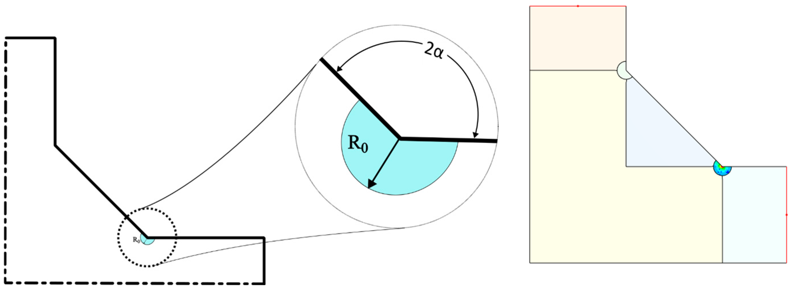
2.1. The Average Strain Energy Density Method (A-SED)

This method uses a local approach based on the strain energy density calculated on a small volume close to a geometrical notch. For a welded joint, this translates into a circular zone centered on the weld toe having radius R0 as per Figure 1.
R 0 = 2 e 1 K 1 A N σ A 1 1 λ 1
For a 90 welded joint, the nominal geometry is known through the angle α.
The radius R0 is a function depending only on the material, so for structural steel, the accepted value is R0 = 0.28 mm [5,6,7]. The SED on this local volume W ¯ can be compared to the limit proof SED value W c to determine the fatigue strength.
W ¯ = W c

Pros and Cons

This approach can be based on FEA results and it shows a great accuracy compared to numerous physical tests [7]. It can be virtually employed in complex joint sections and being a local approach, it also permits the analysis of production defects like plate misalignments. However, this method requires the creation of the “control volume”, on the FE geometry model, this operation can be time-consuming for complex structures or large-scale applications. SED is applied through solid (brick) mesh elements or their planar simplifications, but it is not applicable to shell elements. Even if the method itself is mesh-insensitive, the small size of the control volume requires a huge number of elements for complex joints, leading to a high computational effort being required, plus a not negligible effort to retrieve the results. These elements make this method suitable for detailed analysis, but not for large-scale industrial applications.

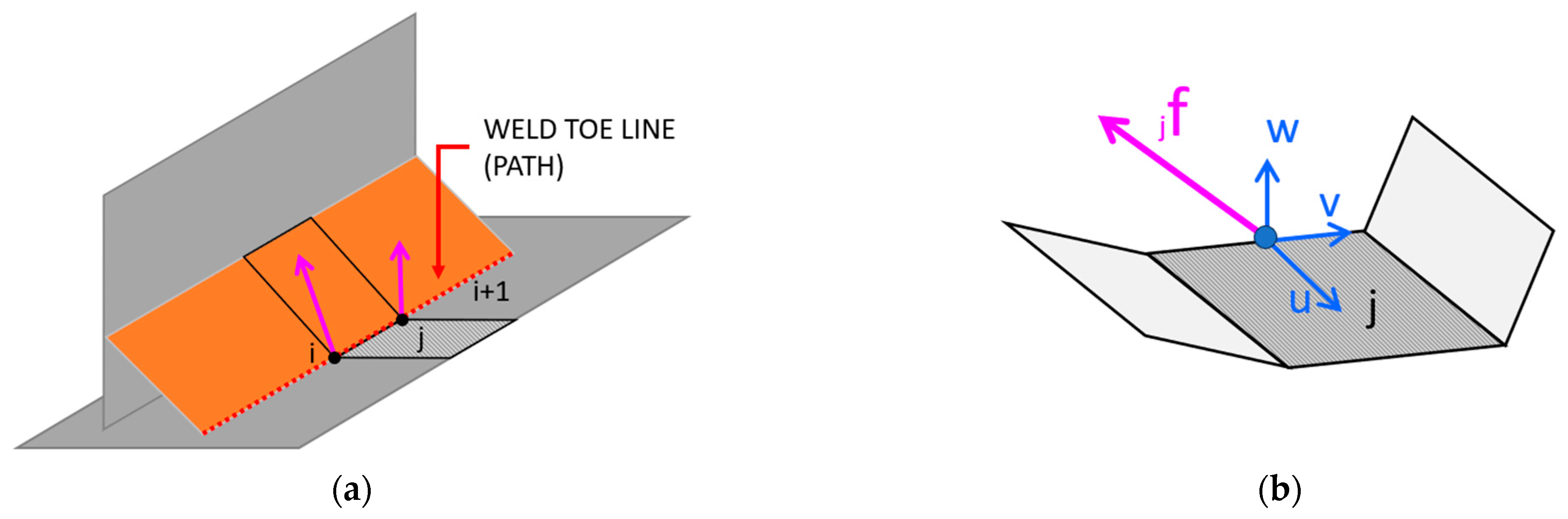
2.2. Deriving Structural Stresses from Elemental Nodal Loads (ENLOs)

This approach aims to gather the stresses of a welded structure at the weld toe or root, based on the element’s nodal loads (forces and moments). The main purpose of this method is to obtain a mesh-insensitive value at the notch that can be used subsequently for typical fatigue calculations.
The unaveraged elemental nodal loads “F” (3 forces and 3 moments) are collected for each element “j” on each node “i” and then distributed among the edge of elements corresponding to the weld toe (or root) depending on the mesh-element length as per Figure 2.
f j = 2 l 2 2 · F n e x t i F p r e v i + 1 + 2 l 2 2 · F p r e v i + 1 F n e x t i 2
In the proposed formulation, the distributed load “jf” is retrieved at the mid-side of each mesh-element “j” [11] and it is projected on an element-local coordinate system. The stresses are then retrieved from simple considerations on the element section, referring to the corresponding area and moment of inertia relative to unit length. The resulting stress is calculated as a combination of the normal portion (membrane stress) and a pure bending component.
σ t o p j = σ m e m b r a n e j + σ b e n d i n g j = f u j t + 6 · m v j t 2
τ t o p j = τ f v j + τ m u j = f v j t + 6 · m u j t 2

Pros and Cons

This method presents a wide series of benefits for industrial application, for example, it is based on shell elements, so its application is immediate for complex geometries and a large number of joints. One of the most interesting benefits is that the stress calculation is a pure post-processing operation so this method can be applied to the output results of a previous static FE Analysis. Due to the use of shell elements and not requiring any form of refinement at the weld toe/root, the number of mesh nodes to analyze is quite small hence the computational effort is extremely low. For these reasons, this method is currently implemented in some commercial software products (nCode Designlife 2003 (Hottinger Brüel & Kjær GmbH, Darmstadt, Germany), Dassault Simulia FeSafe 2022 (Dassault Systèmes SIMULIA Corp., Johnston, RI, USA), …).
However, at the same time, due to these simplifications, it lacks the accuracy typical of more sophisticated methods.

3. The Proposed Model: ENLO-SED

3.1. Main Concept

The proposed method aims to connect the two models mentioned above. It is shown that the SED on the weld toe is mostly dependent on the loads (forces and moments) acting on the section closer to the toe itself, while is almost independent from the “far” loads. This means that it is possible to represent a full-scale FE model (Figure 3a) as a simplified shell model (Figure 3b) and the corresponding local loads can hence be compared to the local SED.

3.2. Background Calibration

The comparison between the SED of the full model and the stresses retrieved from nodal loads from the simplified model is here called “background calibration” (Figure 4) since it aims to find a “compensation factor” to correlate the two results that can be used for the practical application of the method.

3.2.1. SED Model

For this purpose, a simplified 3D model of a welded joint is modeled for the SED application. Multiple values of thickness have been considered, from 2.5 mm to 6.0 mm. Following what was previously stated, this method required a different geometry for each value of the thickness. The mesh type and shape on the critical volume are kept the same for all the models to ensure comparable results.
Unitary distributed loads (forces and moments) are independently applied on the free edge, while the other is fully locked (6 DOFs = 0). The SED is then collected on the critical volume, among the entire joint length with a step of 1 mm.

3.2.2. Structural Stresses Model

The same welded joint is here represented as a trough shell, with the same properties and boundary conditions as the previous one. An important simplification is obtained by using a unique surface 3D model for all the values of the plate thickness. This assumption introduces a minor imprecision since the weld-toe location is dependent on the thickness but has the huge advantage of requiring only one CAD model for all the cases.
The FEA is resolved and the necessary data (nodal loads for the elements at the weld-toe) are extracted and elaborated through a dedicated Python script to retrieve the structural stresses as reported in Equations (4) and (5).

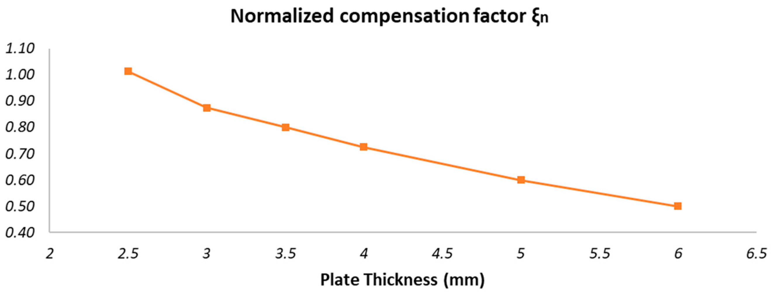
3.2.3. ENLO-SED: Correlation Between the Methods

It is now fundamental to take into account that the stress and the energy have different units, so the stresses are converted to an equivalent linear-elastic energy.
S 2 E N L O 2 E · ξ c o r e , t , z = W A S E D
This energy is compared to the one retrieved from the SED method by means of the parameter “ξ”, which represents a compensation factor and depends on the local geometry (“core”) of the welded joint, the thickness, and the weld size.
This process has been run for different values of the plate thickness from 2.5 mm to 6 mm and showed the behavior reported in Figure 5, where the compensation factor is normalized (“ξn”) by dividing it by 2∙E, with E = Young Modulus of the considered material.
For this range of thicknesses, the compensation factor that best fits the results of the two methods is between 0.50 and 1.00.
Figure 6 represents the strain energy density over the weld-toe path. This shows a very promising adherence between the reference method results (solid lines) and the estimation from nodal loads compensated by the mean of ξn (dashed line) for all the thickness values considered. The global shape of the strain energy is well represented by this approach, while it shows a slightly higher error around the edges due to some border effects and the simplification of this representation.
It is also important to remark that the data processing for the ENLO-SED method is sensibly faster both for the pre-post operation and the FE solution if compared to the application of the full-scale SED method. This is in line with industrial large-scale application requirements and hence it matches the purpose of this method.

4. Operative Workflow

The normalized calibration factor ξn once found can be directly provided to the designers and analysts for the specific solution application. This means that this method, to be applied, only requires the FEA results and all the calculations can take place in postprocessing only (Figure 7). This is a great advantage since the ENLO-SED method can be applied to a pre-existing static FE Analysis. In this work specifically, two distinct Python post-processors have been created, one using general text files to collect data from FE results (applicable with any FE software) and a second dedicated to Ansys using the official pyAnsys library [12]. The GUI is provided by means of a customization of the pyFlow library [13].

5. Results and Conclusions

It has been shown that the results of the SED method can be effectively estimated from detailed FEA results by means of structural stresses on a simplified shell model compensated by a factor ξ. This calculation can be executed as a post-process phase of an existing simplified FE analysis, greatly reducing the pre-processing time and computational effort. In large-scale industrial applications, this allows the ENLO-SED method to be capable of evaluating a huge quantity of welded joints in a short time and with minimal hardware requirements. This can help designers quickly analyze huge amounts of data and find earlier the weak points of a welded structure for punctual detailed analyses.

Author Contributions

Conceptualization, S.L.; methodology, S.L and G.M.; software, S.L.; validation, S.L. and G.M.; formal analysis, S.L and G.M.; investigation, S.L.; resources, F.C.; data curation, S.L.; writing—original draft preparation, S.L.; writing—review and editing, S.L and G.M.; supervision, F.C.; project administration, F.C. All authors have read and agreed to the published version of the manuscript.

Funding

This research received no external funding.

Data Availability Statement

Data will be made available on request.

Conflicts of Interest

The authors declare no conflict of interest.

References

  1. Morettini, G.; Razavi, S.M.J.; Staffa, A.; Palmieri, M.; Berto, F.; Cianetti, F.; Braccesi, C. On the combined use of averaged strain energy density criteria (ASED) and equivalent material concept (EMC) for the fracture load prediction of additively manufactured PLA v-notched specimens. Procedia Struct. Integr. 2023, 47, 296–309. [Google Scholar] [CrossRef]
  2. Morettini, G.; Landi, L.; Burattini, L.; Stornelli, G.; Foffi, G.; Di Schino, A.; Cianetti, F.; Braccesi, C. Application of the Theory of Critical Distance (TCD) to the Breakage of Cardboard Cutting Blades in Al7075 Alloy. Metals 2024, 14, 301. [Google Scholar] [CrossRef]
  3. European Committee for Standardization. EN 1993-1-9: Eurocode 3: Design of Steel Structures—Part 1–9: Fatigue; CEN: Brussels, Belgium, 2005. [Google Scholar]
  4. British Standards Institution. BS 7608:1993—Code of Practice for Fatigue Design and Assessment of Steel Structures; BSI: London, UK, 1993. [Google Scholar]
  5. Foti, P.; Santonocito, D.; Risitano, G.; Berto, F. Fatigue assessment of cruciform joints: Comparison between Strain Energy Density predictions and current standards and recommendations. Eng. Struct. 2021, 230, 111708. [Google Scholar] [CrossRef]
  6. Foti, P.; Crisafulli, D.; Santonocito, D.; Risitano, G.; Berto, F. Effect of misalignments and welding penetration on the fatigue strength of a common welded detail: SED method predictions and comparisons with codes. Int. J. Fatigue 2022, 164, 107135. [Google Scholar] [CrossRef]
  7. Foti, P.; Berto, F.; Filippi, S. Fatigue assessment of welded joints by means of the Strain Energy Density method: Numerical predictions and comparison with Eurocode 3: Numerical predictions and comparison with Eurocode 3. Frat. Ed Integrità Strutt. 2019, 13, 104–125. [Google Scholar] [CrossRef]
  8. Dong, P.; Hong, J.K. The master SN curve approach to fatigue of piping and vessel welds. Weld. World 2004, 48, 28–36. [Google Scholar]
  9. Alencar, G.; Hong, J.K.; de Jesus, A.; da Silva JG, S.; Calçada, R. The Master SN curve approach for fatigue assessment of welded bridge structural details. Int. J. Fatigue 2021, 152, 106432. [Google Scholar] [CrossRef]
  10. Zhu, D.; Ding, Z.; Huang, X.; Li, X. Probabilistic modeling for long-term fatigue reliability of wind turbines based on Markov model and subset simulation. Int. J. Fatigue 2023, 173, 107685. [Google Scholar] [CrossRef]
  11. nCode, an HBM brand. Fatigue Analysis of Seam Welded Structures using nCode DesignLife, Version WPDL_201303-1. Available online: https://cdn.base.parameter1.com/files/base/acbm/ooh/document/2015/05/Whitepaper_SeamWelds_nCodeDesignLife_201303-3.pdf (accessed on 5 September 2024).
  12. Ansys. PyAnsys: An Open-Source Python Library for ANSYS Integration. GitHub. 2024. Available online: https://github.com/ansys/pyansys (accessed on 5 September 2024).
  13. Pedro Cabrera, Pyflow 3.0.0: Visual Scripting Framework for Python. GitHub. 2024. Available online: https://github.com/pedroCabrera/PyFlow (accessed on 5 September 2024).
Figure 1. A-SED. Control Volume and typical angle.
Engproc 85 00032 g001
Figure 2. (a) Schematic example of a welded T-joint including weld-toe line (weld path); (b) example of nodal loads on element-local coordinate system.
Engproc 85 00032 g002
Figure 3. (a) Full-scale FE model for SED (core section); (b) simplified equivalent shell FE model.
Engproc 85 00032 g003
Figure 4. Calibration workflow: full-scale SED model vs. proposed simplified model.
Engproc 85 00032 g004
Figure 5. Normalized compensation parameter ξn versus plate thickness.
Engproc 85 00032 g005
Figure 6. Comparison between reference SED and the estimated value with ENLO-SED (mJ).
Engproc 85 00032 g006
Figure 7. Application workflow, with dedicated node-based GUI. [*] indicates a reqired field.
Engproc 85 00032 g007
Disclaimer/Publisher’s Note: The statements, opinions and data contained in all publications are solely those of the individual author(s) and contributor(s) and not of MDPI and/or the editor(s). MDPI and/or the editor(s) disclaim responsibility for any injury to people or property resulting from any ideas, methods, instructions or products referred to in the content.

