Next Article in Journal
Investigating the Effect of Performing Secondary Tasks on Reaction Time While Driving by Computer Analysis
Previous Article in Journal
Model Order Reduction Applied to Replicate Blast Wave Interaction with Structure
 
 
engproc-logo
Article Menu

Article Menu

Proceeding Paper

Numerical Thermo-Structural Simulations for the Design of the Havar Beam Window of a Beryllium Target for Neutron Beam Production †

by
Roberta Dattilo
1,2
1
Department of Industrial Engineering (DII), University of Padova, Via Venezia 1, 35132 Padova, Italy
2
INFN, Laboratori Nazionali di Legnaro (LNL), Viale dell’Università 2, 35030 Legnaro, Italy
Presented at the 53rd Conference of the Italian Scientific Society of Mechanical Engineering Design (AIAS 2024), Naples, Italy, 4–7 September 2024.
Eng. Proc. 2025, 85(1), 28; https://doi.org/10.3390/engproc2025085028
Published: 26 February 2025

Abstract

The present work was carried out as part of the PRIN 2022JCS2CN project “CoolGal”, which aims to design and manufacture a beryllium target cooled by Galinstan (a liquid metal alloy at room temperature) for the production of neutrons using energetic protons. The objective of the present work is to thermo-structurally design a beam window that encloses the environment in which the target is housed. The window consists of a Havar disk, the thickness of which must be minimized to absorb the least amount of proton beam power, while its diameter must be sufficient to avoid excessive beam loss. The window will then be embedded around its perimeter and will have to withstand two load conditions, applied individually: A mechanical load, due to the atmospheric pressure of 0.11 MPa during vacuuming, and a thermal load, due to heating during irradiation with the proton beam. Once a first-version window geometry was defined, a static structural finite element analysis (FEA) was carried out by activating geometric nonlinearities to assess the structural integrity of the window under mechanical loading. After that, a static thermal–mechanical FEA analysis was carried out to assess the structural integrity of the window under thermal loading. Given the compressive stress state induced by thermal loading and the slenderness of the window itself, a nonlinear buckling structural FEA analysis was also performed.

1. Introduction

The PRIN 2022JCS2CN project “CoolGal: A Liquid Metal-Cooled Beryllium Target for a Proton-Induced Neutron Production” [1], funded by MIUR, serves as the target for the initial phase (phase-0) of the Neutron and Proton Irradiation Facility (NEPIR) [2]. NEPIR is part of the “delta-phase” of the SPES (Selective Production of Exotic Species) project [3,4,5], located at LNL (Laboratori Nazionali di Legnaro); it will use the SPES Cyclotron [6] to produce both quasi-monoenergetic fast neutron beams in the 20–70 MeV energy range and a continuous energy neutron beam intended to simulate natural atmospheric neutrons in the 1–70 MeV energy range.
The primary application of the NEPIR is studying radiation damage to digital electronics and materials, both inert and biological, through their interactions with neutron beams. Neutron-induced damage in microelectronics is increasingly important due to the growing demand for such controls in high-reliability systems not only for avionics at flight altitudes but at sea-level as well.
The objective of the CoolGal project is to design the target system and ancillary components of the facility where the target is to be located. When irradiated with protons from the SPES Cyclotron, the target, in beryllium, will produce a beam of neutrons. The structure containing the target, explained in Section 2.1 (Figure 1), is sealed by a thin Havar disk [7], called the beam window. This paper focuses on optimizing the design of this window. The primary objectives are to minimize its thickness while maintaining structural integrity, ensuring its resistance to atmospheric pressure during chamber vacuuming, and evaluating its structural integrity under thermal loads induced by proton beam irradiation. Special attention will be given to the thermal-induced buckling problem.
The validation of the design of this type of components is often performed by experimental testing under in-service loading [8,9] or by using empirical equations, such as those provided by Los Alamos, to verify a foil window under a static pressure load [10].
It is worth noting that the in-service conditions of these types of windows as treated in the literature are often different compared to the one treated in this paper. For example, the target chamber is typically pressurized so that when the beam irradiates the window, the pressure load also acts on the window, along with the thermal load [11,12]. This is the reason why the possible buckling phenomenon is typically neglected in the works available in the literature, the pressure being the critical load in such cases.
The goal of this paper is to validate the beam window design using FEA.

2. Materials and Methods
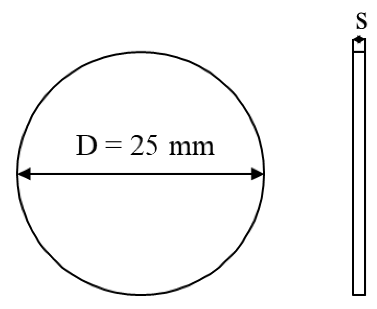
2.1. Case Study

The structure of the target system is illustrated in Figure 1. A beryllium target is secured to the bottom of the chamber by a plate pulled down by five springs and is cooled by a water-cooling system at the bottom of the chamber. The chamber is sealed by a fixed beam window made of Havar [7]. This window must isolate the target from the rest of the facility to prevent radioactive and toxic products from interacting with the broader beam line.
In general, when interacting with a material, energetic protons will lose energy to electrons, ionizing atoms via the Coulomb interaction or more rarely, undergo nuclear interactions with the atomic nuclei. The energy lost to ionization is the dominant reaction; only a fraction (~10%) of the protons will produce neutrons. For the purpose of this study, we assume that the energy of the protons deposited in the material occurs in the form of ionization.
In CoolGal, the beryllium target is thick in the sense that the protons lose all their kinetic energy: the beam is stopped and all the power of the beam is deposited (P = 70 W for I = 1 µA and E = 70 MeV). Instead, the Havar window is thin, but therein, the protons will also deposit ionization energy. Although the maximum proton energy of the SPES cyclotron is 70 MeV, we will consider the worst-case scenario, in which the protons reach maximum ionization, which happens when the beam energy is E = 35 MeV, the minimum SPES energy.
The material selected for the design of the window for this application is Havar, a high-resistance cobalt alloy. Three types of Havar are commercially available, i.e., annealed (A), cold rolled (CR), cold rolled and heat treated (CRHT), characterized by different treatments that affect only the material yield strength. The yield strength gradually increases from the annealed (A) to the cold rolled and heat treated (CRHT) configuration, and the reason for this is explained in detail in Ref. [13].
In this application Havar CR is chosen, and the material properties are reported in Table 1.
The geometry of the window (Figure 2) is a thin disk with a diameter of 25 mm, determined by the size of the proton beam spot. The beam cannot be collimated to a smaller diameter due to the geometric and beam optical constraints of the neutron production beam line. The thickness of the window “s” needs to be designed with the objective of minimization.
This study considers thicknesses ranging from 0.05 to 0.1 mm, based not only on the need to minimize power absorption but also on the availability of the material from the supplier.

2.2. Loading Conditions

The window is subjected to two main loads, as mentioned in the introduction, as follows:
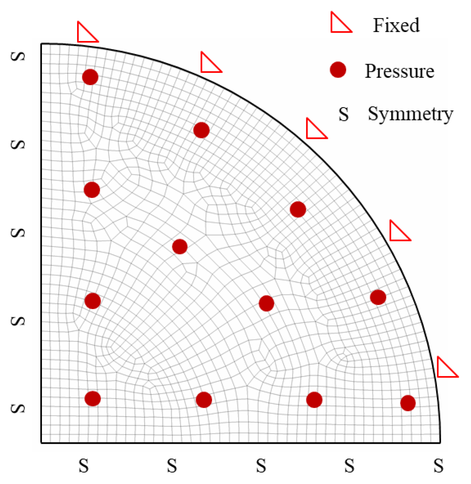
  • Atmospheric pressure—applied to the window during the vacuum reduction of the chamber (Figure 3a). Once the entire beam of the facility is under vacuum, this load is no longer active. In this type of application, it is important to maintain the whole beam line under vacuum to avoid possible oxidation of the components.
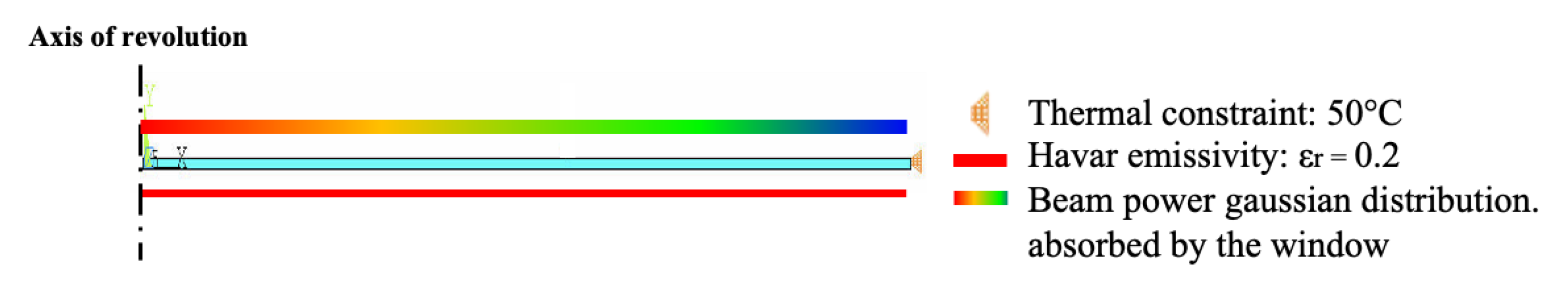
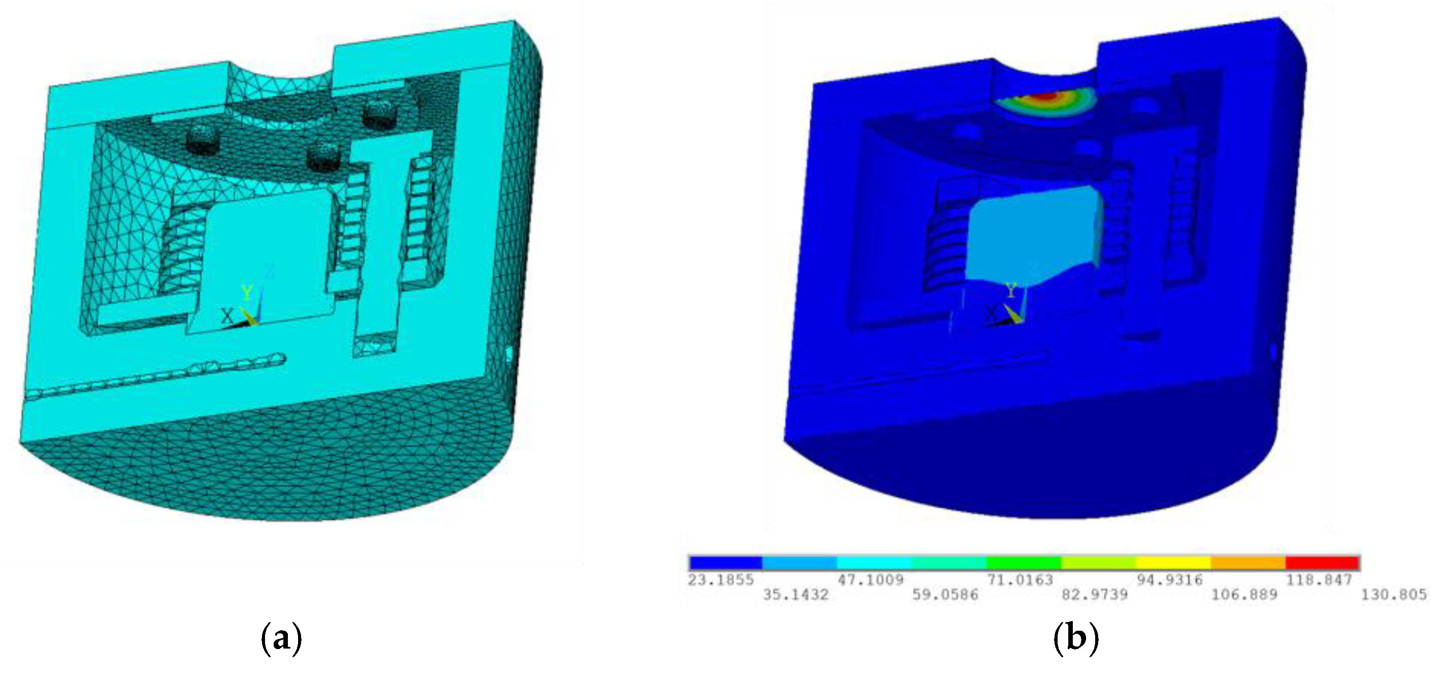
  • Thermal load—induced by the proton beam during facility operation (Figure 3b).
When the proton beam irradiates the beam window, a portion of its power is deposited on the window, causing a temperature increase. This power deposition depends on the proton beam characteristics and the geometry of the window, particularly its thickness.
The proton beam is simulated using a Gaussian distribution centered on the beam axis. The deposition function of the beam power is described by Equation (1).
p r = P · f ( s ) 2 · π · σ 2   · e x p ( r 2 2 · σ 2 )
where P is the power of the beam (P = 35 W); f is the absorption factor, which is a function of the thickness ( f s = 0.27 · s , where 0.27 is a material property that can be easily calculated by SRIM software [14]); σ is the standard deviation of the beam; r is the radial position on the surface window; and p is the power density of the beam normalized by the thickness. The beam standard deviation is an input determined by beam optic considerations, and it has been defined to be σ = 5   m m .

2.3. FE Software

All FE analyses in this paper were carried out using ANSYS Mechanical APDL® 2022 R2 commercial software (ANSYS Inc., Canonsburg, PA, USA) [15,16]. The following elements were employed:
  • Structural Analysis: 2D quadrilateral SHELL181 4-node elements were used to enable all analyses to be conducted with the same converged mesh, as the thickness varies.
  • Thermal Analysis: 2D quadrilateral PLANE77 8-node axisymmetric elements were utilized.
Furthermore, in the structural and buckling analyses, the nonlinear solver was activated to account for geometric nonlinearities. This was necessary due to the window’s slenderness, which places the analysis within the large displacement hypothesis.

3. Numerical Results

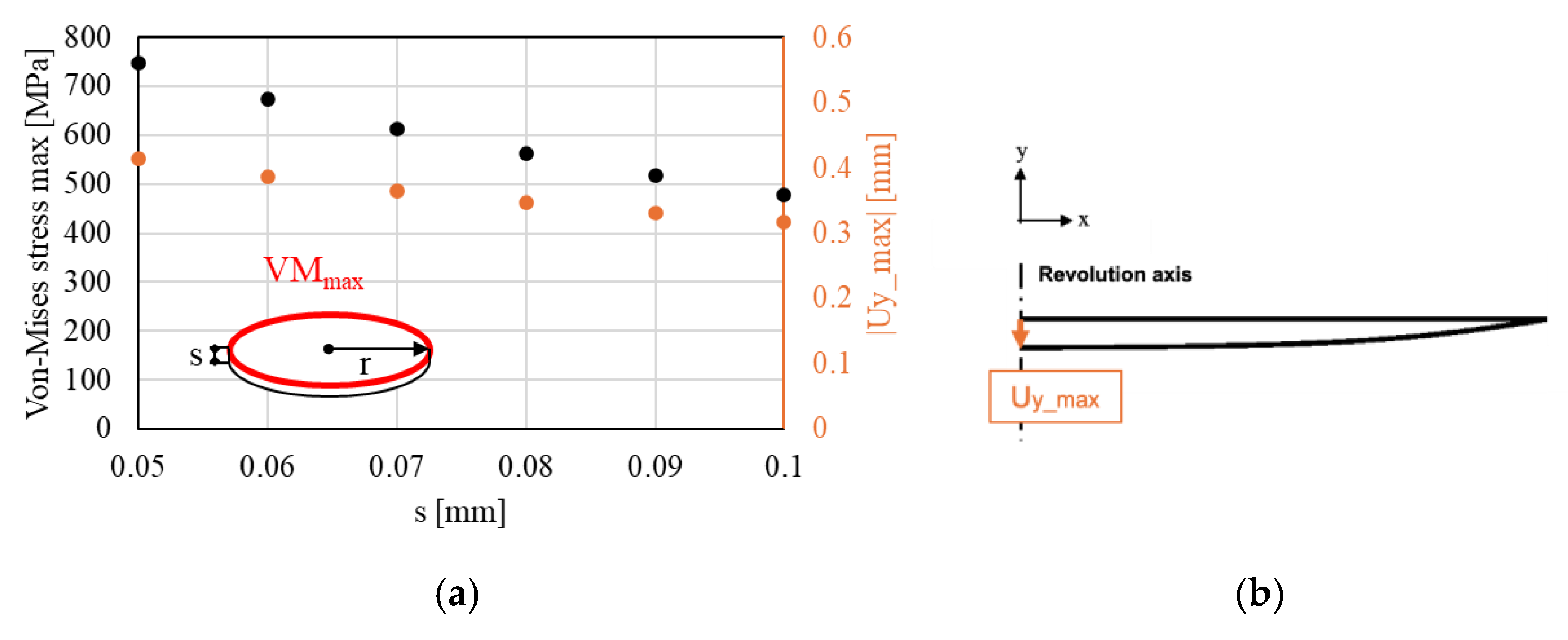
3.1. Structural Analysis Under Vacuum Conditions

The finite element analysis (FEA) is performed using the model represented in Figure 4. Due to the symmetry of the problem, only one quarter of the window is modeled using 2D Shell 181 4-node elements of the Ansys element library. A free mesh, with global element size d = 0.3 mm, is used, the outer line is fixed, and symmetry boundary conditions are imposed on the radial lines; then, the atmospheric pressure is applied to the surface (p = 0.11 MPa).
Given the slenderness of the structure, the assumption of small displacement is not correct. In this case, the diaphragm stress (stress in the middle surface of the plate) of the structure becomes significant, and the plate becomes stiffer than what would be expected from a simulation under small displacements, as highlighted in Ref. [17] (pp. 448–450) and Ref. [18]. For this reason, the analysis is solved using the non-linear solver to account for geometric non linearities due to large displacements.
The results, expressed in terms of maximum von Mises stress and maximum out-of-plane displacement, are reported in Figure 5 as a function of the plate thickness “s” in the range between 0.05 and 0.1 mm.

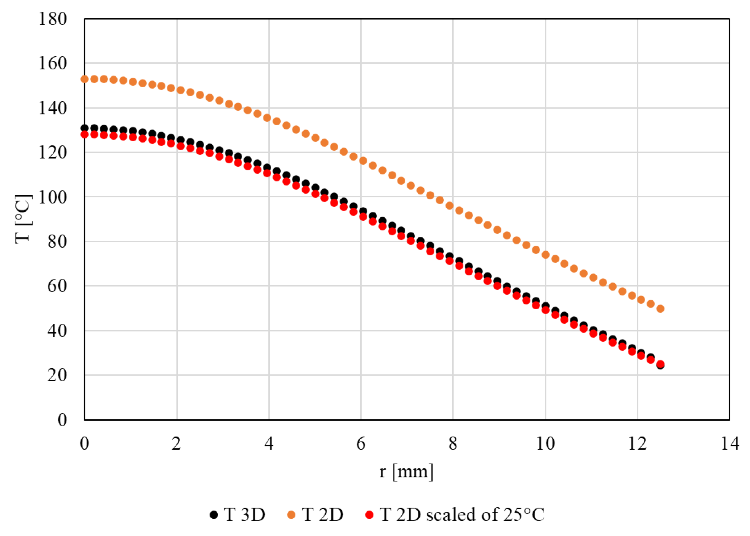
3.2. Thermal Analysis

The FEA is conducted using a 2D simplified model (Figure 6), in which only the beam window is considered, and the other components that fix the window are taken into consideration only by using thermal constraints derived from experience. In the model, 2D PLANE77 8-node axisymmetric elements are used to define the free mesh pattern, with a global element size d = 0.01mm. As mentioned above, a thermal constraint of 50 °C has been applied at the outer line to simulate the temperature of the component which will fix the window. The thermal load consisted of the power of the beam absorbed by the window, calculated by Equation (1).
The relative emissivity of Havar (ε = 0.2) has been applied to one side of the window to simulate radiation with the other components of the structure. It is assumed that radiation on the side facing the target is negligible due to the high temperature of the target.
The analysis has been performed for all considered thicknesses without changing the global size of the free mesh pattern, as thermal simulations do not require refined meshes to achieve convergence. The temperature distributions along the window radius for selected thicknesses are shown in Figure 7. This trend is typical of this type of condition, with a maximum temperature reached at the disk center, as also demonstrated in Ref. [19].
This simplified 2D model has the advantage of reducing computational time. The results of such a model have been validated against a thermal analysis of the complete 3D geometry, with an Havar beam window having a thickness s = 0.1 mm and power of the beam P = 30 W. The 3D thermal FE model and the temperature plot are shown in Figure 8.
By comparing the temperature trends for the window as derived by 2D or 3D FE analyses (Figure 9), it can be observed that the 2D model accurately captures temperature trends, but it exhibits a constant offset ΔT = +25 °C. This is caused by the thermal constraint of 50 °C applied into the 2D FE model instead of 25 °C, which is the actual temperature achieved by the grasping system. The 2D simulation was not updated with a thermal constraint of 25 °C, as the temperature trend obtained with 50 °C provides a conservative estimate for the following structural analysis.

3.3. Thermal–Structural Analysis

The temperature derived from the thermal FE analysis has been used as input for a coupled thermal–structural FE analysis. This analysis has been conducted only for the window with thickness s = 0.1 mm, being the worst case scenario. In such a case, the non-linear solver option was not activated, and the reference temperature of the window was set to 25 °C (room temperature).
The results in terms of the von Mises stress along the window radius are shown in Figure 10.

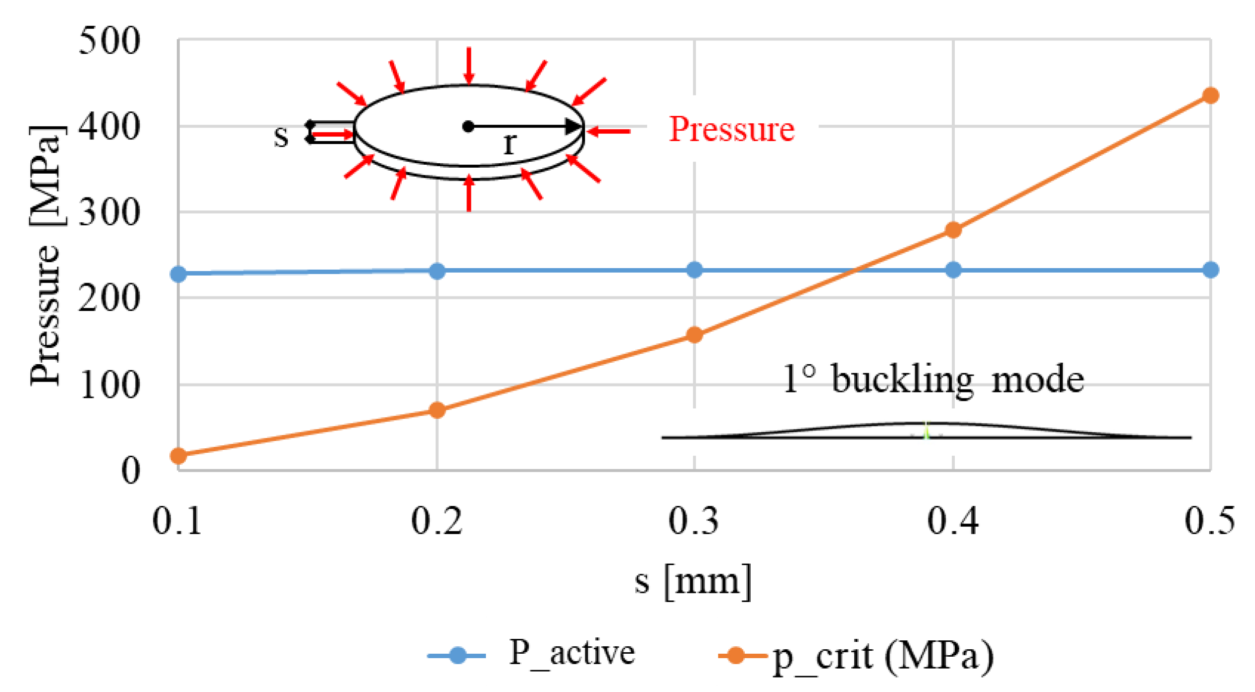
3.4. Buckling Analysis

Due to the structure’s slenderness and the compressive nature of the stress field, a buckling analysis is necessary. First, a linear elastic eigenvalue analysis was conducted on the beam window to determine its critical pressure for various thicknesses. This was then compared with the active pressure at the outer diameter, obtained from the thermal–structural analysis described in Section 3.3, conducted for thicknesses between 0.1 mm and 0.5 mm. In particular, the constraint reaction in the radial direction (Fr) was derived from the thermal–structural simulation, and the active pressure was calculated using Equation (2):
p = F r π · D · s D = d i a m e t e r o f   t h e   w i n d o w ,   s = t h i c k n e s s   o f   t h e   w i n d o w
The results are shown in Figure 11.
These results indicate that the structure must have a minimum thickness of 0.4 mm to avoid buckling deformation. However, the window considered in the context of the CoolGal project should not be thicker than 0.1mm. Therefore, the buckling analysis has been furtherly investigated.
Considering the theory proposed by Timoshenko [20], it is possible to treat the window under buckling conditions as a structure in equilibrium under external loads. In fact, Timoshenko studied a simple case of a fixed beam subjected to a load higher than the critical load using the large displacement hypothesis. In this case, the beam does not deform indefinitely but finds an equilibrium position [20].
Since the only load acting on the window is the one that produces buckling, we can accept the deformation under the action of the buckling load. For this reason, a non-linear buckling analysis has been conducted in Ansys Mechanical APDL® 2022 R2 (ANSYS Inc., Canonsburg, PA, USA) [16] (pp. 194–195), [15] (pp. 325–327). The model used is the same as the one employed in Section 3.1, Figure 4, for geometry, element type, mesh type, and constraints. The analysis is conducted using the following iterative solutions:
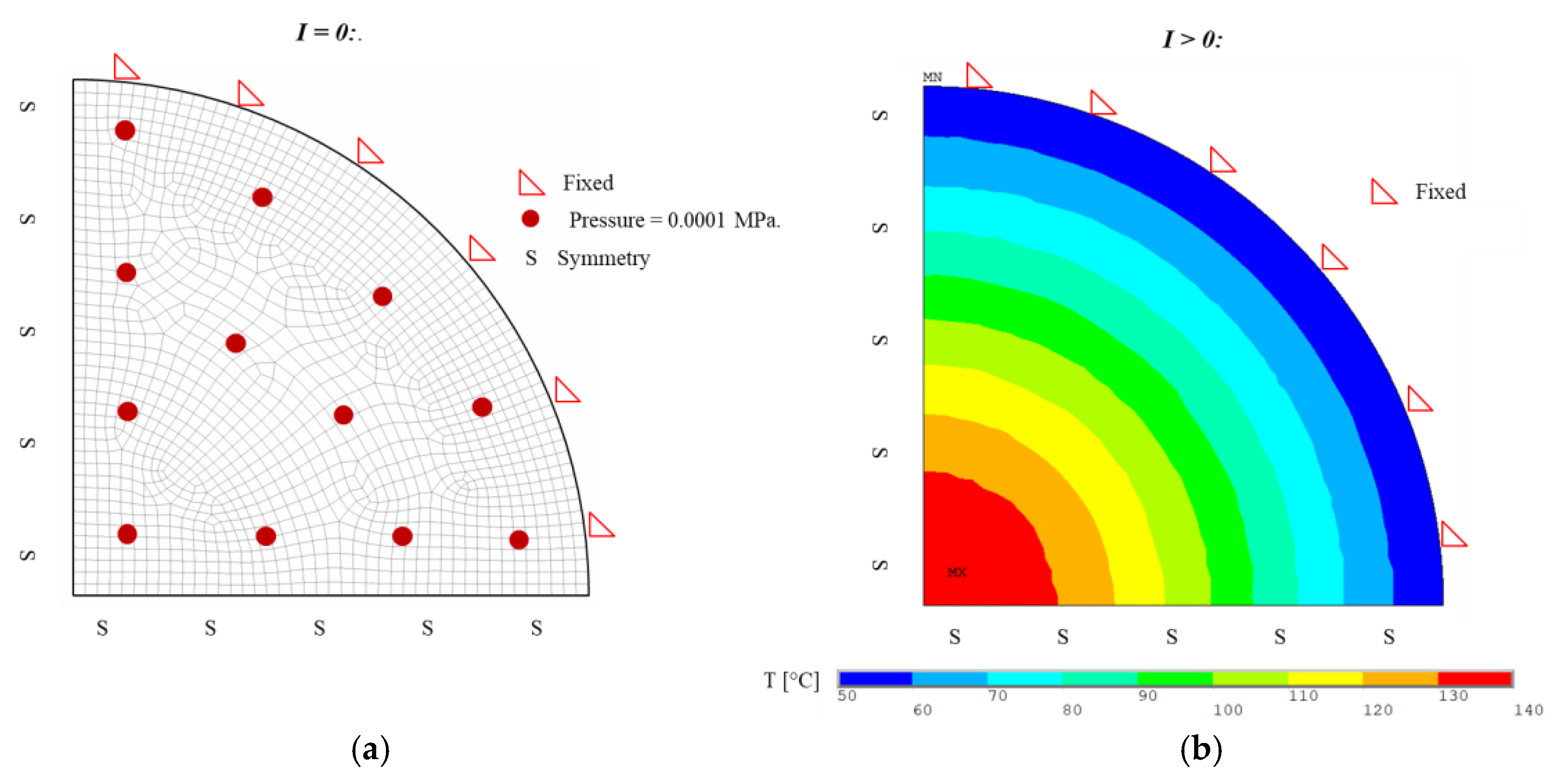
  • First iteration (I = 0): A perturbating pressure load is applied, as shown in Figure 12a. This loading allows a small geometric deformation of the window, creating the conditions for the buckling simulation to begin. This load is calibrated so as not to affect the results of the simulation (p = 0.0001 MPa).
  • Subsequent iterations (I > 0): As shown in Figure 12b, the thermal load is applied gradually at each iteration until it reaches the output temperature trend of the associated thermal analysis (Section 3.3).
The results of the non-linear buckling analysis are shown in Figure 13 in terms of maximum von Mises stress and maximum out-of-plane displacement as a function of the disk thickness.
Two limitations of the thermal–structural analysis deserve to be mentioned. First, all simulations were conducted using the material properties of Havar at room temperature. This simplification was considered acceptable due to the relatively low temperatures reached by the window under the studied conditions (approximately 140 °C). However, for more extreme operational scenarios or higher beam powers, this assumption may need to be revisited, as material properties could change significantly at elevated temperatures.
Secondly, potential changes in material properties resulting from proton beam irradiation were not accounted for in this study. This omission was primarily due to a lack of comprehensive information in the existing literature regarding the effects of prolonged exposure to high-energy particle beams on Havar’s mechanical and thermal properties. The only paper found treating such a phenomenon reported that the window tested in the facility at the SARAF accelerator exhibited a brittle failure during irradiation with a 3.6 MeV proton beam [9]. No other information was found regarding the material mechanical properties, with the exception of Ref. [21], which reported the properties of a SS316L foil, tested using the small punch method after proton beam irradiation. This gap in our knowledge underscores the need for further research into the mechanical behavior of Havar under operational conditions like those in the NEPIR facility.

4. Discussion

The numerical validation of the design of a Havar beam window for the NEPIR facility has provided valuable insights into its structural integrity and thermal behavior under in-service conditions.
The 2D structural analysis under vacuum condition demonstrated that the designed window is able to sustain the atmospheric pressure, even with a reduced thickness (Figure 5). In fact, all the analyzed thicknesses in the range between 0.05 and 0.1 mm provided a maximum von Mises stress lower than the material yield strength.
The 2D thermal analysis allows for the derivation of the temperature distribution along the window radius for various thicknesses (Figure 7). The simplified 2D FE model proved to be a computationally efficient and reasonably accurate representation, with a constant temperature offset of +25 °C compared to that of the more complex 3D model (Figure 9). This offset, resulting from the thermal constraint assumptions, provides a conservative estimate for subsequent structural analyses, enhancing the safety factor of the design considerations.
The coupled thermal–structural FE analysis, performed for the 0.1 mm thick window, provided the numerical validation of the beam window for the thermal load under the worst case scenario. However, the most significant findings came from the buckling validation. The initial eigenvalue analysis indicated that a minimum thickness of 0.4 mm would be required to prevent buckling under the applied loads (Figure 11). This presented a challenge, as the design constraints limit the maximum thickness to 0.1 mm. To address this, a non-linear buckling analysis has been performed on the basis of Timoshenko’s theory of elastic stability. This approach allowed us to treat the window as a structure in equilibrium under loads exceeding the critical buckling load, accounting for large displacements. The iterative solution method started using a small perturbating pressure and gradually applied the thermal load (Figure 12). The results of the non-linear buckling analysis (Figure 13) suggest that even at thicknesses below the theoretically required 0.4 mm, the window can achieve a stable equilibrium under the applied thermal loads, with a maximum von Mises stress that does not exceed the material yield strength. This finding is crucial for the feasibility of the current design, as it allows for the use of thinner windows that minimize beam interference while maintaining structural integrity. Interestingly, the analysis reveals that as the thickness of the window decreases, the maximum stress also decreases. This phenomenon can be attributed to the nature of the thermal load, which varies minimally with thickness changes. The analyses are conducted under conditions of nearly constantly imposed deformation. As the stiffness of the structure decreases with reduced thickness, the resulting stresses are consequently lower.
The conclusion we draw from the FE analysis is that a window thickness of 0.05 mm achieves the best compromise in regards to balancing the needs of structural integrity and minimal power beam absorption.
However, it is important to note that further experimental validation and potential design iterations may be necessary to fully optimize the window for long-term operation in the NEPIR facility. Three critical issues for future work have been identified:
  • Experimental validation of the nonlinear buckling analyses. The predictions made in this paper, particularly regarding the window’s behavior under loads exceeding the critical buckling load, require experimental validation. This validation will ensure the reliability of the design under actual operating conditions.
  • Characterization of Havar material properties at high temperatures. To perform reliable thermal–structural simulations, especially under scenarios involving higher proton beam powers, it is crucial to obtain accurate material data for Havar at elevated temperatures (up to 500 °C, the temperature limit often used for the Havar after it loses most of its structural properties). This characterization will enable more precise predictions of the window’s performance under extreme operational scenarios.
  • Characterization of Havar material properties after irradiation with a proton beam. This will ensure that the window does not collapse under in-service conditions due to an embrittlement of the material caused by proton beam irradiation.

5. Conclusions

This study has successfully validated the design of a 0.05 mm thickness Havar beam window for the NEPIR facility through comprehensive numerical analyses, with a particular focus on the non-linear buckling analysis, which proved crucial in overcoming the apparent thickness limitations of 0.4 mm initially suggested by linear eigenvalue analysis. A validation of a computationally efficient 2D model for thermal analysis has also been performed.
While these results support the feasibility of the current design, they also highlight the need for further research. Future work should focus on the experimental validation of the non-linear buckling analysis, the characterization of Havar properties at high temperatures (up to 500 °C), and the investigation of material changes due to proton beam irradiation.

Funding

We acknowledge the financial support provided under the National Recovery and Resilience Plan (NRRP), Mission 4, Component 2, Investment 1.1, call for tender No. 104, published on 2 February 2022, by the Italian Ministry of University and Research (MUR), funded by the European Union NextGenerationEU Project, “CoolGal: A Liquid Metal-Cooled Beryllium Target for a Proton-Induced Neutron Production”—Code MUR 2022JCS2CN_002—CUP C53D23001500001—Grant Assignment Decree No. 974, adopted on 30/06/2023 by the Italian Ministry of University and Research (MUR).

Institutional Review Board Statement

Not applicable.

Informed Consent Statement

Not applicable.

Data Availability Statement

All data are contained within the present article.

Acknowledgments

The author offers sincere gratitude to the University of Padua, represented by A. Campagnolo, for their invaluable academic support and resources. I would also like to express my appreciation to the Laboratori Nazionali di Legnaro (LNL) of the Istituto Nazionale di Fisica Nucleare (INFN), represented by A. Monetti. Their facilities and technical support have been crucial in the development of my research. Finally, I thank the University of Cassino, represented by J. Wyss, for its collaboration and insightful contributions to this study. Their expertise has greatly enhanced the depth and breadth of this research.

Conflicts of Interest

The author declares no conflicts of interest.

References

  1. Barrera, R.A.; Bisello, D.; Esposito, J.; Mastinu, P.; Prete, G.; Silvestrin, L.; Wyss, J. CoolGAL: A Galinstan bathed Be fast neutron production target at the NEPIR facility. EPJ Web Conf. 2020, 231, 03002. [Google Scholar] [CrossRef]
  2. Mastinu, P.; Bisello, D.; Barrera, R.A.; Porras, I.; Prete, G.; Silvestrin, L.; Wyss, J. Fast neutrons at LNL Legnaro. J. Neutron Res. 2020, 22, 233–247. [Google Scholar] [CrossRef]
  3. Monetti, A.; Andrighetto, A.; Petrovich, C.; Manzolaro, M.; Corradetti, S.; Scarpa, D.; Rossetto, F.; Martinez Dominguez, F.; Vasquez, J.; Rossignoli, M.; et al. The RIB production target for the SPES project. Eur. Phys. J. A 2015, 51, 128. [Google Scholar] [CrossRef]
  4. Andrighetto, A.; Manzolaro, M.; Corradetti, S.; Scarpa, D.; Monetti, A.; Rossignoli, M.; Ballan, M.; Borgna, F.; D’Agostini, F.; Gramegna, F.; et al. Spes: An intense source of Neutron-Rich Radioactive Beams at Legnaro. J. Phys. Conf. Ser. 2018, 966, 012028. [Google Scholar] [CrossRef]
  5. Gramegna, F.; Prete, G.; Andrighetto, A.; Antonini, P.; Ballan, M.; Bellato, M.; Bellan, L.; Benini, D.; Bisoffi, G.; Bermudez, J.; et al. The SPES exotic beam ISOL facility: Status of the project, technical challenges, instrumentation, scientific program. Il Nuovo Cimento C 2018, 41, 195–201. [Google Scholar] [CrossRef]
  6. Maggiore, M.; Campo, D.; Antonini, P.; Lombardi, A.; Manzolaro, M.; Andrighetto, A.; Monetti, A.; Scarpa, D.; Esposito, J.; Silvestrin, L. SPES: A new cyclotron-based facility for research and applications with high-intensity beams. Mod. Phys. Lett. A 2017, 32, 1740010. [Google Scholar] [CrossRef]
  7. Havar® • UNS R30004. Hamilton Precision Metal. Available online: https://www.hpmetals.com/-/media/ametekhpmetals/files/havar.pdf?la=en&revision=c2fb2204-9a60-4c3b-b923-7ba40b6f72cd&hash=8B18F671C0462F3388F3989E6472163C (accessed on 6 June 2024).
  8. Bennett, J.R.J.; Bruno, L.; Densham, C.J.; Drumm, P.V.; Edgecock, T.R.; Fabich, A.; Gabriel, T.A.; Haines, J.R.; Heseroth, H.; Hayato, Y.; et al. A Proposal to the ISOLDE and Neutron Time-of-Flight Experiments Committee. 2004, p. 10. Available online: https://inspirehep.net/literature/856492 (accessed on 10 May 2024).
  9. Silverman, I.; Kijel, D.; Arenshtam, A.; Gavish, I.; Lavie, E.; Meroz, E.; Weismann, L.; Kreisel, A.; Eliyahu, I.; Zemach, E.; et al. SS316L AS WINDOW FOR PRODUCTION TARGET FOR Ge-68. In Proceedings of the 11th International Topical Meeting on Nuclear Applications of Accelerators, AccApp 2013, Bruges, Belgium, 5–8 August 2013; pp. 226–230. [Google Scholar]
  10. Cryogenicse, W.V.; Gray, W.H. Thin windows for gaseous and liquid targets: An optimization procedure. Cryogenics 1975, 15, 627–638. [Google Scholar] [CrossRef]
  11. Gallmeier, F.X. Ge-68 PRODUCTION TARGET USING 30 MEV 1 MA PROTONS AT SARAF. In Proceedings of the 10th International Topical Meeting on Nuclear Applications of Accelerators 2011, AccApp 2011, Knoxville, TN, USA, 3–7 April 2011; pp. 352–356. [Google Scholar]
  12. Shaiju, V.; Sharma, S.; Kumar, R.; Sarin, B. Target foil rupture scenario and provision for handling different models of medical cyclotrons used in India. J. Med. Phys. 2009, 34, 161. [Google Scholar] [CrossRef] [PubMed]
  13. Haroush, S.; Moreno, D.; Silverman, I.; Turgeman, A.; Shneck, R.; Gelbstein, Y. The Mechanical Behavior of HAVAR Foils Using the Small Punch Technique. Materials 2017, 10, 491. [Google Scholar] [CrossRef] [PubMed]
  14. Ziegler, J.F.; Ziegler, M.D.; Biersack, J.P. SRIM The Stopping and Range of Ions in Matter, 2008; software.
  15. ANSYS Mechanical APDL® Verification Manual; ANSYS Inc.: Canonsburg, PA, USA, 2020.
  16. ANSYS Mechanichal APDL® Structural Analysis Guide; ANSYS Inc.: Canonsburg, PA, USA, 2020.
  17. Young, W.C.; Budynas, R.G.; Roark, R.J. Roark’s Formulas for Stress and Strain, 7th ed.; Reprint in McGraw-Hill international edition, General engineering series; McGraw-Hill: New York, NY, USA, 2011. [Google Scholar]
  18. Kraytermane, B.L.; Fu, C.C. Nonlinear Analysis of Clamped Circular Plates. J. Struct. Eng. 1985, 111, 2402–2415. [Google Scholar] [CrossRef]
  19. Votawe, J.R.; Nickles, R.J. A theoretical description of the beam induced heating of accelerator target foils. Nucl. Instrum. Methods Phys. Res. Sect. A Accel. Spectrometers Detect. Assoc. Equip. 1989, 281, 216–223. [Google Scholar] [CrossRef]
  20. Timoshenkoe, S.P.; Gere, J.M. Theory of Elasstic Stability, 2nd ed.; McGraw-Hill International Book Company: New York, NY, USA, 1985. [Google Scholar]
  21. Snir, Y.; Moreno, D.; Silverman, I.; Samuha, S.; Eisen, Y.; Eliezer, D.; Gelbstein, Y.; Haroush, S. Mechanical properties of proton bombarded SS316L thin foils using the small punch technique. J. Nucl. Mater. 2020, 540, 152340. [Google Scholar] [CrossRef]
Figure 1. Project PRIN CoolGal: mechanical design of the target.
Engproc 85 00028 g001
Figure 2. Geometry of the beam window made of Havar.
Engproc 85 00028 g002
Figure 3. (a) Atmospheric pressure load on the window; (b) thermal load induced by the proton beam.
Engproc 85 00028 g003
Figure 4. A one-quarter 2D FE model of the window discretized using the Shell 181 4-node elements (Ansys Mechanical APDL® 2022 R2 (ANSYS Inc., Canonsburg, PA, USA)). The figure highlights both the loading and constraint conditions.
Engproc 85 00028 g004
Figure 5. (a) Trend of the maximum von Mises stresses and the maximum displacement Uy as a function of the thickness; (b) location of the maximum displacement of the structure.
Engproc 85 00028 g005
Figure 6. Simplified 2D FE model of the window defined for the thermal analysis (Ansys APDL® 2022 R2 (ANSYS Inc., Canonsburg, PA, USA)).
Engproc 85 00028 g006
Figure 7. Temperature trend along the radius of the window for thicknesses s = 0.05 mm, s = 0.07 mm, and s = 0.1 mm. The proton beam power used for all these simulations is P = 35W.
Engproc 85 00028 g007
Figure 8. (a) The 3D thermal FE model discretized with 20-node SOLID90; (b) temperature plot of the 3D thermal analysis.
Engproc 85 00028 g008
Figure 9. Comparison of the temperature trend along the radius of the window between the simplified 2D model (orange dots indicators), the simplified model scaled using −25 °C (red dots indicators), and the 3D model (black dots indicators).
Engproc 85 00028 g009
Figure 10. Von-Mises stresses along the window radius.
Engproc 85 00028 g010
Figure 11. Comparison between critical pressure (p_crit) and active pressure (P_active) at the window for thicknesses from 0.1 mm to 0.5 mm.
Engproc 85 00028 g011
Figure 12. The 2D FE model for the non-linear buckling analysis: (a) for the first iteration (I = 0) of the solution, a perturbating pressure load is applied; (b) from the second iteration on (I > 0), the heat load is applied gradually at each iteration until it reaches the steady-state load.
Engproc 85 00028 g012
Figure 13. Trend of the maximum Von Mises stress and the maximum displacement Uy as the thickness varies for the last iteration of the non-linear buckling analysis.
Engproc 85 00028 g013
Table 1. Material properties of Havar CR at ambient temperature [7].
Material Properties of Havar (CR) at Tamb
UTS [MPa]1860
Yield Strength [MPa]1724
E [MPa]203,400
Density [kg/m3]8300
Thermal Conductivity [W/(m × K)]13
Thermal Expansion Coefficient [K−1]12.5 × 10⁻⁶
Disclaimer/Publisher’s Note: The statements, opinions and data contained in all publications are solely those of the individual author(s) and contributor(s) and not of MDPI and/or the editor(s). MDPI and/or the editor(s) disclaim responsibility for any injury to people or property resulting from any ideas, methods, instructions or products referred to in the content.

