
Product Design to Improve the Measurement and Projection of Mill Liner Wear †


Abstract
1. Introduction
2. Methodology
2.1. Planning
2.1.1. General Objective
- To design a tool that allows us to assess the condition of mill liners and estimate the approximate replacement time.
2.1.2. Specific Objectives
- Manage timely replacement and procurement of liners.
- Reduce unplanned plant shutdowns in mining companies.
2.1.3. Target Audience
2.1.4. Companies Offering Solutions
2.2. Concept Development
- Instantaneous projection of current lining dimensions.
- Agile data capture process to reduce exposure time within the mill.
- Individual operation tool with exclusive access to information.
- Ability to generate a basic report immediately after data capture.
- Precision in measurements taken.
- Adequate measurement capacity for mill linings with diameters of 10 to 25 feet.
- Ergonomic and lightweight design to allow for single-user operation.
- Economical solution compared to 3D tools.
- Compatible for export to AutoCAD.
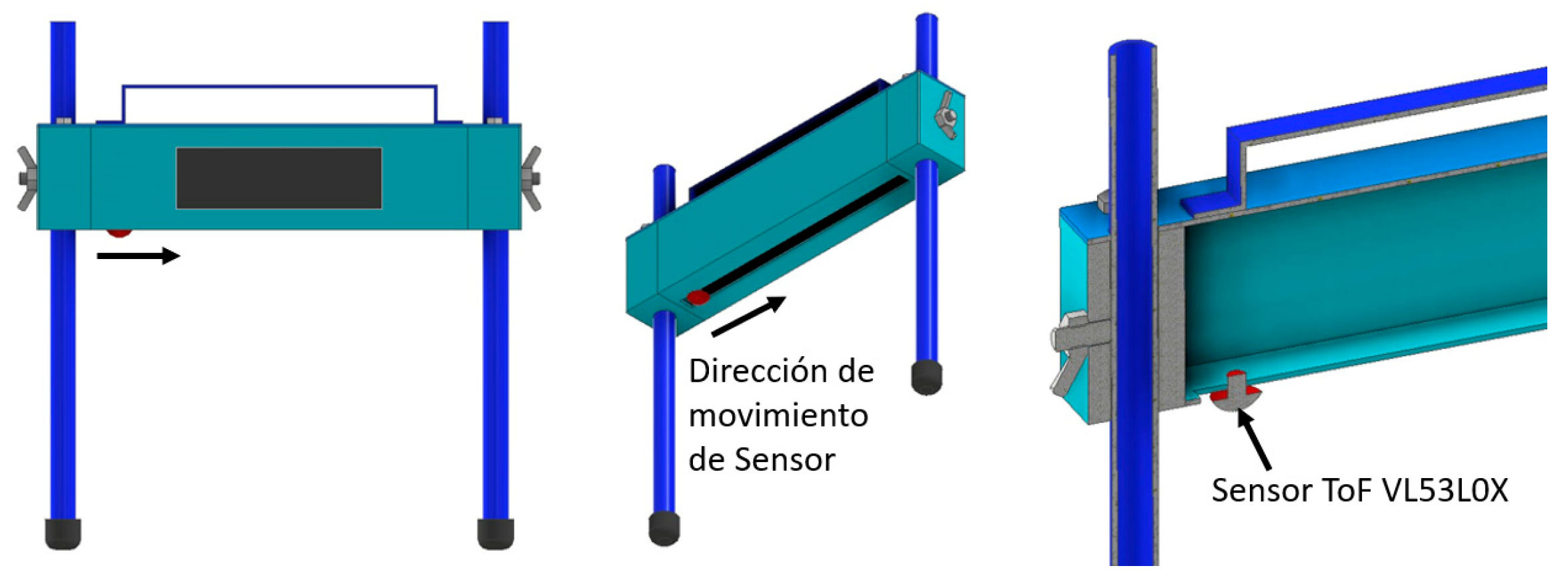
2.3. System Level Design
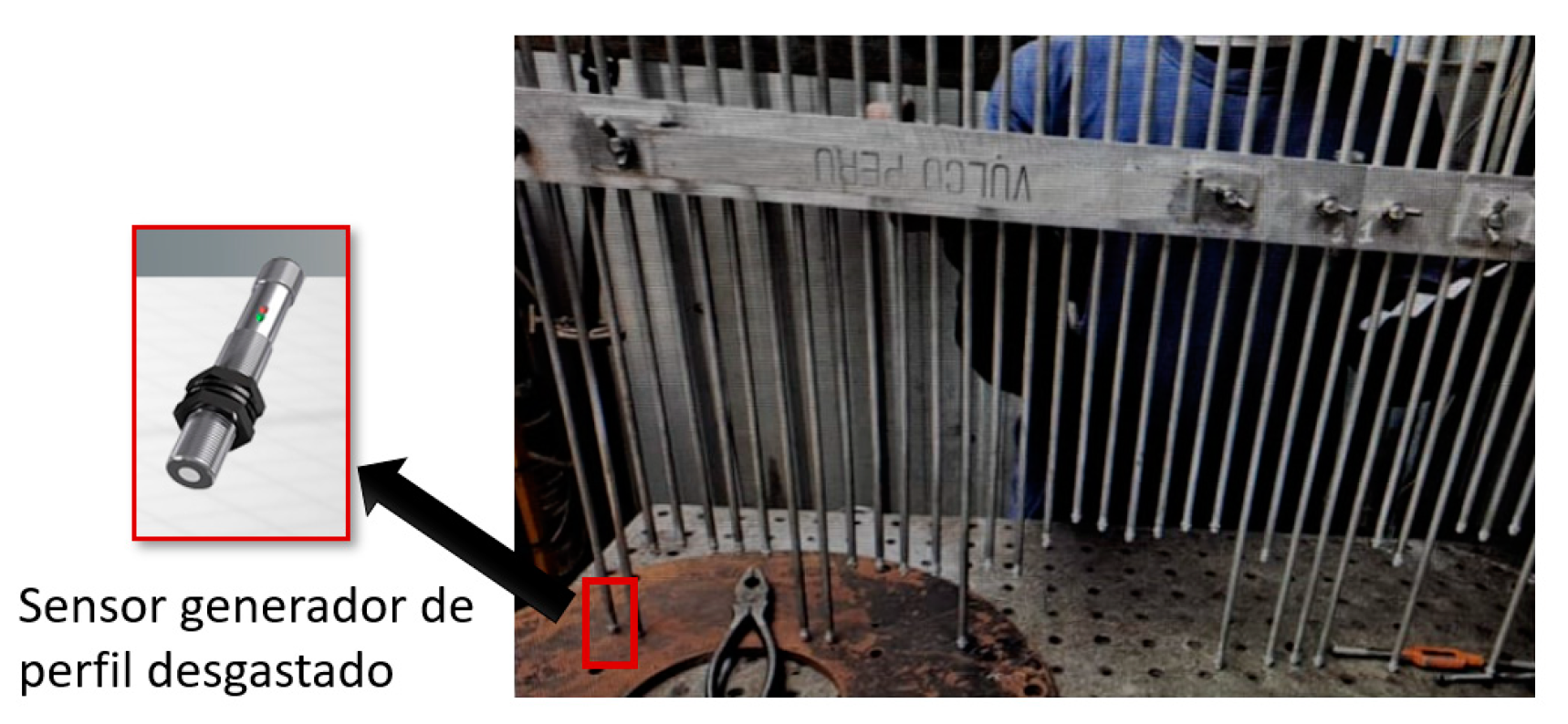
- Sensor: VL53L0X;
- Operating Voltage: 2.6 V to 5.5 V;
- Power Consumption: 10 mA (average current, may vary depending on configuration or environment);
- Maximum Distance Range: 200 cm;
- Accuracy: ±1 mm;
- Interface: I2C;
- Size: 0.5″ × 7″.
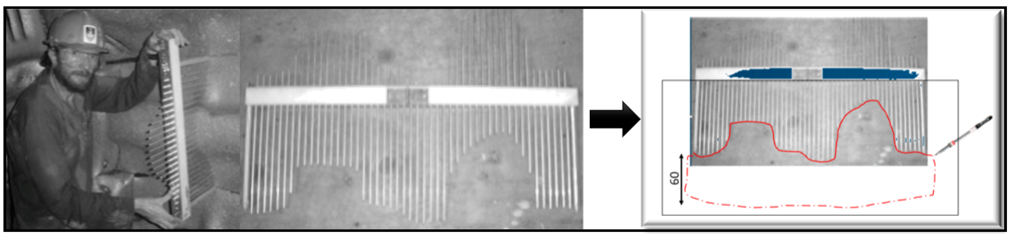
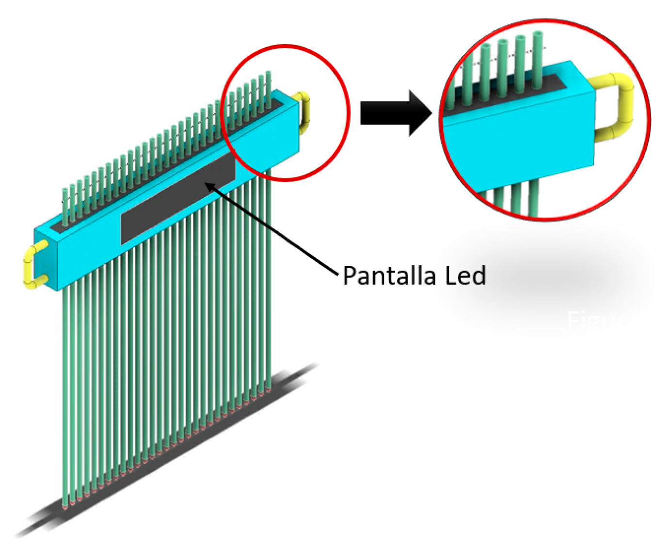
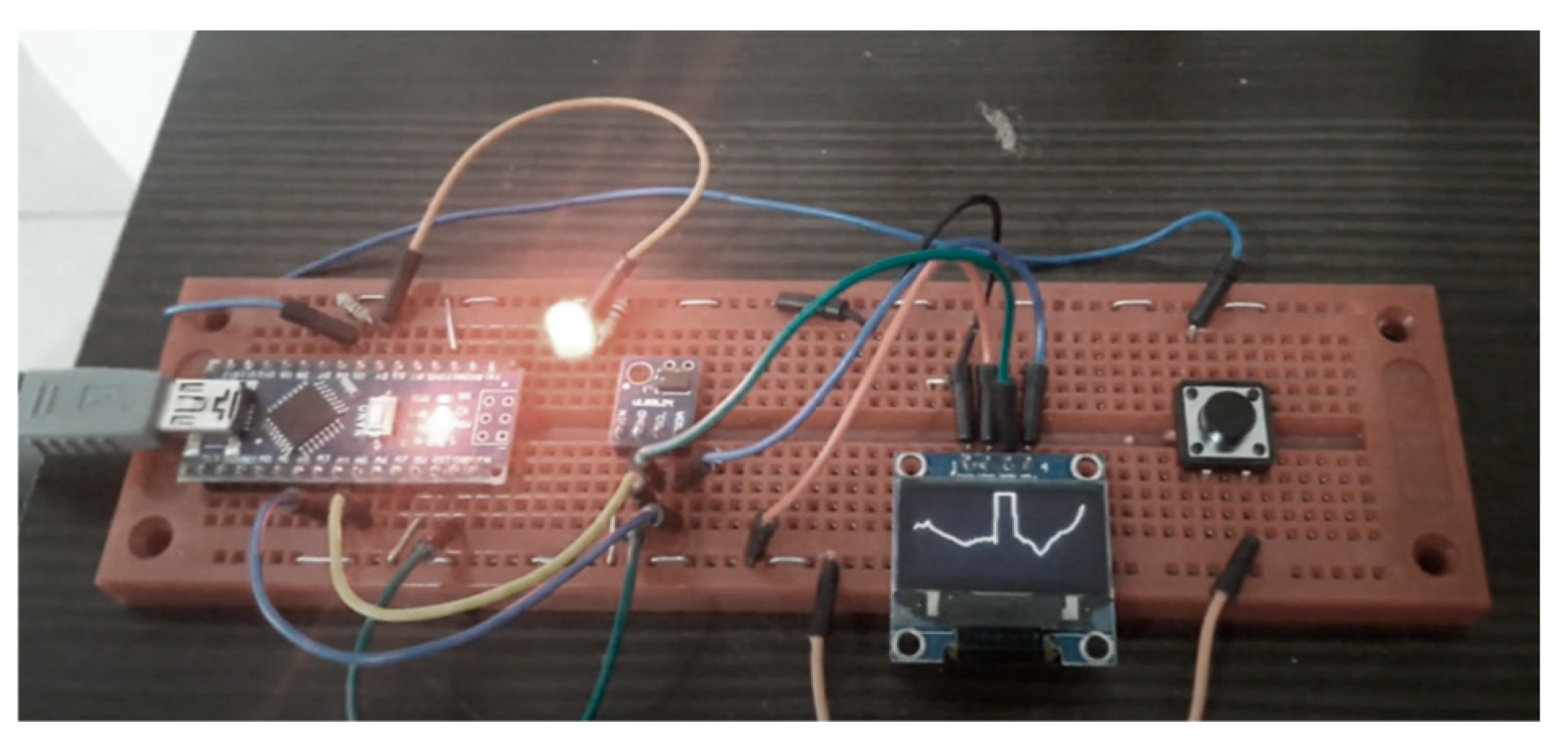
2.4. Detail Design
2.5. Testing and Refinement
3. Results
4. Conclusions
Author Contributions
Funding
Institutional Review Board Statement
Informed Consent Statement
Data Availability Statement
Conflicts of Interest
References
- Expomina 2023. Available online: https://expominaperu.com/ (accessed on 25 October 2023).
- Improvement System in the Management of Plant Mining Processes (Crushing and Grinding). Available online: https://www.scribd.com/document/463123126/Sistema-de-mejora-en-la-gestion-de-los-procesos (accessed on 2 November 2023).
- Optimizing the Life Cycle of Cylinder Liners in a 2000TMSD 8′x10 Ball Mill. Available online: https://alicia.concytec.gob.pe/vufind/Record/UUNI_bc54a5eaa21d4cc3eeb7dd06cd46185e (accessed on 2 November 2023).
- Optimization of Maintenance in the Change of Linings in the Fuller Mill of the Company 88 Southern Peru—Toquepala. Available online: https://repositorioslatinoamericanos.uchile.cl/handle/2250/3277665 (accessed on 2 November 2023).
- Design and Simulation of Manipulator for Steel Linings Applied in Conventional Mills. Available online: https://repositorioslatinoamericanos.uchile.cl/handle/2250/9371477 (accessed on 2 November 2023).
- Mathematical Model for Estimating the Useful Life of Linings in Semi-Autogenous Mills. Available online: http://cybertesis.uach.cl/tesis/uach/2006/bmfcia773m/doc/bmfcia773m.pdf (accessed on 2 November 2023).


| Investigation | Technology Type | Document | Scope |
|---|---|---|---|
| “Optimization of the cylinder liners’ lifecycle in an 8′ × 10′ ball mill—2000 TMSD” [3] | Manufacturing of liners | Undergraduate Thesis—National University of Engineering—2014 | Showcased the alloy and chemical composition change in the liners, successfully extending their lifespan. |
| “Optimization of maintenance during liner replacement in the Fuller mill at Southern Peru Company—Toquepala—2015” [4] | Reliability-centered maintenance | Undergraduate Thesis—National University of the Altiplano—2015 | Analyzed the company’s system; subsequently, with knowledge and data collection, developed the codification of liner criticality, enabling reliability-centered maintenance. |
| “Design and simulation of a manipulator for steel liners applied in conventional mills” [5] | Automation | Undergraduate Thesis—National University of the Altiplano—2018 | Successfully optimized mill maintenance by reducing liner changes and operational costs. |
| “Mathematical model for estimating the lifespan of liners in semi-autogenous mills” [6] | Mathematical model | Undergraduate Thesis—Austral University of Chile—2015 | Design and development of a mathematical model, utilizing descriptive statistics and programmable algorithms, to estimate the lifespan of liners. |
| N° | Items | Interpretation of Questions |
|---|---|---|
| 1 | How long does it take you to generate a report on mill liner wear once you have obtained the information? | To determine the time required to generate a mill liner wear and projection report. |
| 2 | How long does it take you to gather on-site information? | To establish the time spent inside the mill taking measurements. |
| 3 | How many people assist you in gathering information to assess wear measurements? | To ascertain the number of individuals involved in taking measurements inside the mill. |
| 4 | Does the client request immediate information once you finish taking measurements? | To understand whether the client requests information immediately. |
| 5 | How soon does the client request information? | To determine the maximum number of days the client needs to estimate the next inspection or replacement of mill liners. |
| 6 | What is the precision of your measurement tool? | To assess the precision of the current measurement tool in use. |
| 7 | What tool do you use for taking measurements? | To identify the typical tool utilized. |
| 8 | What measurements are typically included in the mill report? | To gather information on the dimensions of the mill typically visited to define the prototype measurement. |
| 9 | How often are plant shutdowns scheduled to inspect wear? | To determine the frequency of mine visits for mill liner inspections. |
| 10 | What is the approximate weight of the current measurement tool? | To estimate the approximate weight required to define the prototype. |
| 11 | How much would you be willing to pay for a tool that provides instant measurement and wear projection? | To approximate the potential cost of our prototype. |
| 12 | Would you like the projections and graphs generated by the tool to be viewable and projectable with AutoCAD? | To determine if engineers require projections to be saved or utilized in the company’s standard format. |
| N° | Items | Interpretation of Results |
|---|---|---|
| 1 | How long does it take you to generate a report on a mill liner wear once you have obtained the information? | 53.1% of the surveyed engineers take more than a week to complete a report because they have to return to Lima to process the data. |
| 2 | How long does it take you to gather on-site information? | 50% of the surveyed engineers take between 30 min to 1 h because they take measurements of different parts of the mill. |
| 3 | How many people assist you in gathering information to assess wear measurements? | 50% of the surveyed engineers indicate that 3 people enter the mill for inspection. |
| 4 | Does the client request immediate information once you finish taking measurements? | 87.5% of the surveyed engineers indicate that the client requests information upon leaving the mill. |
| 5 | How soon does the client request information? | 71.9% of the surveyed engineers stated that the client requests their wear report within 4 to 5 days at most. |
| 6 | What is the precision of your measurement tool? | 65.6% of the surveyed engineers indicate that the margin of error of their tool is ±5 mm. |
| 7 | What tool do you use for taking measurements? | 87.5% of the surveyed engineers indicate that the most used tool is the Faro Focus 3D Scanner, followed by manual measurement (winches and vernier), and finally the manual comb. |
| 8 | What measurements are typically included in the mill report? | 71.9% of the surveyed engineers indicate that the mills with the most inspections are of diameter 10 to 25 feet. |
| 9 | How often are plant shutdowns scheduled to inspect wear? | 59.4% of the surveyed engineers indicate that they travel to the mine every 3 months for mill inspection during plant shutdown. |
| 10 | What is the approximate weight of the current measurement tool? | 40.6% of the surveyed engineers indicate that their measurement tool weighs between 10 and 20 kg. |
| 11 | How much would you be willing to pay for a tool that provides instant measurement and wear projection? | 59.4% of the surveyed engineers indicate that they would pay between $2000.00 to $5000.00 for a tool with instant wear projection. |
| 12 | Would you like the projections and graphs generated by the tool to be viewable and projectable with AutoCAD? | 90.6% of the surveyed engineers indicate that they need the tool results to be compatible with AutoCAD. |
| Phase | Description |
|---|---|
| Definition of the problem | Currently, there are no practical tools or alternatives that provide rapid and accurate wear reports to assess the state and wear projection of mill liners during a plant shutdown. |
| Analysis of the contradiction | Technical Contradiction: The need to obtain wear projections in graphs and tables through an application versus the need for a comprehensive and detailed report on the condition of the liners. Physical Contradiction: The fragility of a practical tool versus potentially being less than that of a current tool. |
| Using TRIZ principles | Modularity Principle: Removable parts for easy and safe transportation to the mine. Quick disassembly. |
| Solution selection | Designing a prototype with an incorporated sensor capable of measuring distances on the X–Y axes of the liners. |
| Solution implementation | To enable measurement, a motor is incorporated to move the sensor across the width of the liner. |
| Evaluation and improvement | Evaluation: Tests will be conducted to calibrate the sensor measurements. Projected wear curves are also simulated on the screen installed in the digital comb. Improvement: An application is added to visualize wear curves and projections on a mobile phone without the need to access the mill. |
| Phase | Digital Comb for Measuring Mill Linings |
|---|---|
| Replace | Sensors: 29 position and measurement sensors. Sensors: 1 laser sensor that moves across the width of the liner. |
| Combine | The old design of the manual comb with sensor technology. |
| Fit | The visualization of wear curves and projections on a cellphone through an application. |
| Modify | 29 aluminum tubes are replaced by only 2 tubes used for positioning the prototype. |
| Purpose or Properties | Additional uses: It can measure and project lifespan. |
| Eliminate | The interior rubber for tube grip is removed. |
| Re fix or revert | Welding points are modified for stoppage by butterfly nuts at the ends. The wear visualization is changed from a mini-screen integrated into the tool to a visualization on a mobile device with important data and images of the state of the liners. |
| N°. | Metrics | Unit | Value |
|---|---|---|---|
| 1 | Total weights | Kg. | 3.5 |
| 2 | Maximum measuring width | mm. | 350 |
| 3 | Maximum measuring height | mm. | 400 |
| 4 | Sensor measurement accuracy | mm. | ±3 |
| 5 | Screen size (width by height) | mm. | 200 × 60 |
| 6 | Motor Driver L298N | und. | 1 |
| 7 | Comb size (height × length × width) | mm. | 515 × 505 × 75 |
| 8 | Power button | und. | 1 |
| 9 | Adjustment and positioning nut. | und. | 2 |
Disclaimer/Publisher’s Note: The statements, opinions and data contained in all publications are solely those of the individual author(s) and contributor(s) and not of MDPI and/or the editor(s). MDPI and/or the editor(s) disclaim responsibility for any injury to people or property resulting from any ideas, methods, instructions or products referred to in the content. |
© 2025 by the authors. Licensee MDPI, Basel, Switzerland. This article is an open access article distributed under the terms and conditions of the Creative Commons Attribution (CC BY) license (https://creativecommons.org/licenses/by/4.0/).
Share and Cite
Castañeda-Quilcaro, F.D.; Cordova-Yavar, C.L.; Vidal Endara, R.F. Product Design to Improve the Measurement and Projection of Mill Liner Wear. Eng. Proc. 2025, 83, 4. https://doi.org/10.3390/engproc2025083004
Castañeda-Quilcaro FD, Cordova-Yavar CL, Vidal Endara RF. Product Design to Improve the Measurement and Projection of Mill Liner Wear. Engineering Proceedings. 2025; 83(1):4. https://doi.org/10.3390/engproc2025083004
Chicago/Turabian StyleCastañeda-Quilcaro, Francklyn David, Clelia Lucero Cordova-Yavar, and Rubén Felipe Vidal Endara. 2025. "Product Design to Improve the Measurement and Projection of Mill Liner Wear" Engineering Proceedings 83, no. 1: 4. https://doi.org/10.3390/engproc2025083004
APA StyleCastañeda-Quilcaro, F. D., Cordova-Yavar, C. L., & Vidal Endara, R. F. (2025). Product Design to Improve the Measurement and Projection of Mill Liner Wear. Engineering Proceedings, 83(1), 4. https://doi.org/10.3390/engproc2025083004