Abstract
Elbow injuries are the second most common upper extremity fractures and often require invasive and costly surgical treatments. To explore a non-surgical alternative, we present the development and evaluation of a custom 3D-printed static orthosis made from polylactic acid (PLA) designed using 3D scanning, CAD software-based modeling and material characterization, showing promise for broader application in similar elbow injuries.
1. Introduction
The elbow is considered one of the most important joints in the human upper limb. It is composed of three key bones: the distal humerus, the proximal ulna (olecranon), and the head of the radius, allowing movements such as flexion, extension, and rotation. However, this joint is directly exposed to potential damage, cracks, or fractures because it is not protected by soft tissue. Elbow fractures are considered the second most frequent among upper extremity fractures, only behind shoulder fractures in workplace accidents [1]. The most common mechanism of elbow injury is a fall with the limb in extension [2]. Most olecranon fractures tend to occur in individuals aged 50 years or older, typically following a fall from standing height. Younger individuals are more likely to experience injuries associated with a high energy injury mechanism [3].
Patients experience challenges in both their professional and personal performance due to the physical limitations imposed by the fracture. These issues can have a significant impact on the patients’ quality of life and psychosocial well-being [4]. Olecranon fractures, like supracondylar fractures, can be treated either surgically or non-surgically. If they are Type II or III according to the Mayo scale [5], surgical management is usually recommended. However, depending on the clinical assessment by the treating physician, non-surgical alternatives can be explored, involving a period of immobilization of 8 to 10 weeks using a splint that maintains the arm flexed at a 90-degree angle [6]. Following this, therapy exercises involving progressive continuous extension are used, avoiding complete active extension of the elbow.
In this paper, we will focus on the development of a specialized static orthosis using additive manufacturing with polylactic acid (PLA) for the non-surgical treatment of olecranon elbow fractures. The emphasis lies in creating a customized solution tailored to the unique anatomical characteristics of the patient. Utilizing advanced 3D printing technology, we have crafted an orthosis that ensures precise and stable immobilization, following the VDI 2221 standard. This innovative approach aims to provide a cost-effective and noninvasive alternative to traditional surgical interventions. The orthosis was designed with breathable features, considering comfort during the crucial recovery period. The paper will delve into the methodology, incorporating 3D scanning processes, CAD software-based modeling, material characterization, and mechanical tests as part of the design process. Ultimately, the methodology presented aims to serve as a foundation for developing tailored orthotic solutions applicable to a wider range of fractures and injuries.
2. Methodology
2.1. Orthosis Design Process
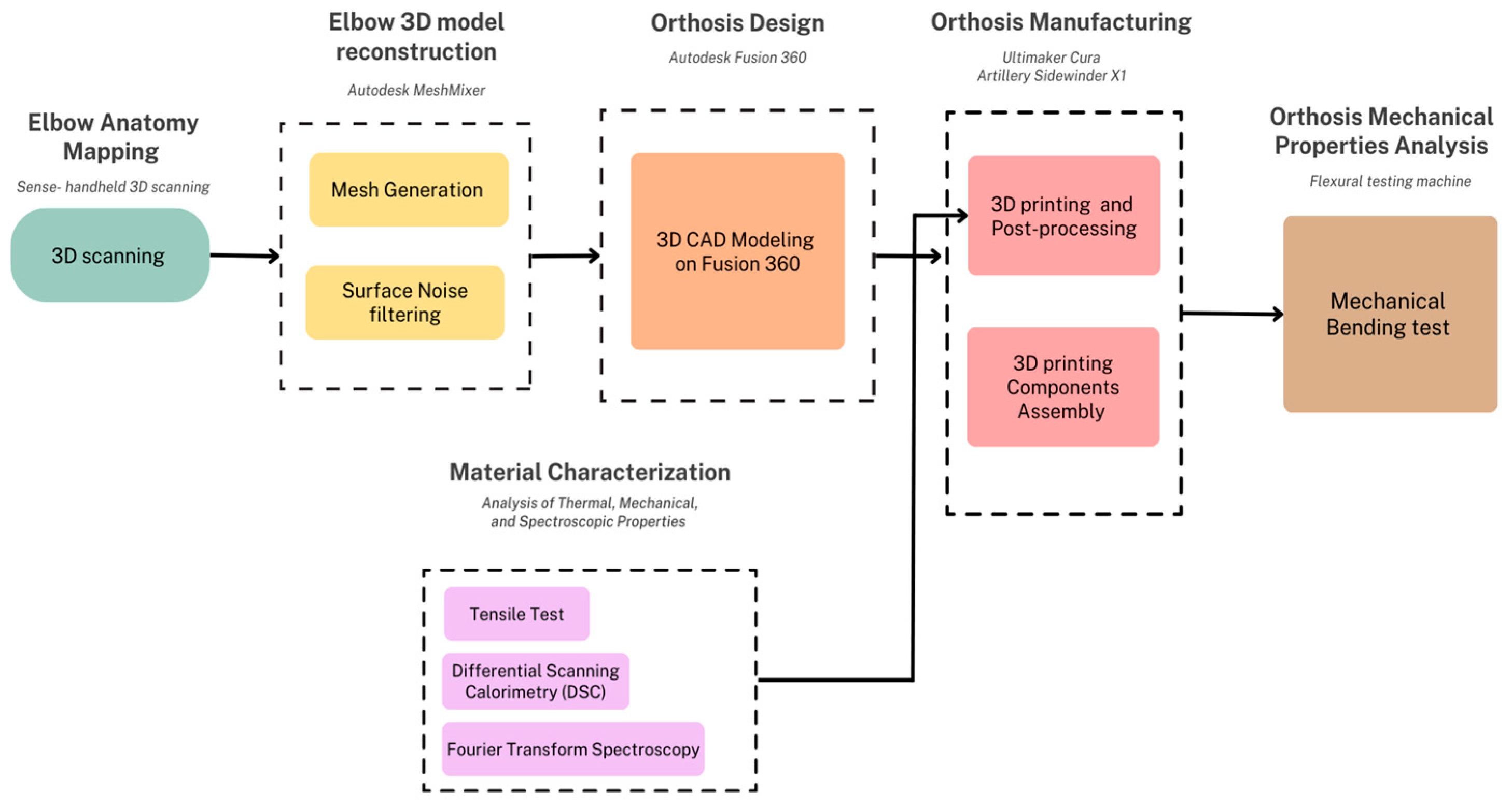
A custom 3D-printed elbow orthosis was designed following the schematic diagram illustrated in Figure 1. To customize the orthosis according to the anatomy of the patient, prototyping began by scanning the left elbow with a 3D laser scanner, Sense. The acquired data underwent a series of transformations and filtering on Meshmixer software v.3.5, in order to generate a clean elbow mesh (the structural build of a 3D model consisting of polygons). Next, the 3D model of the orthosis was constructed over the elbow mesh in Fusion 360 software v.2.0.14344, an Autodesk CAD-based software. Subsequently, the model was refined for ergonomics purposes, and Voronoi holes were incorporated to enhance breathability and ensure proper distribution of the daily use forces to which the orthosis will be subjected. Additionally, openings were incorporated with the intention to facilitate the attachment and detachment of the orthosis using elastic bands, which enable users to secure or remove the orthosis as needed. In parallel to this process, the characterization of the chosen material PLA was carried out in 3 different tests: tensile test, Differential Scanning Calorimetry, and Fourier transform spectroscopy. These analyses facilitated the determination of the most suitable printing parameters for the 3D-printing manufacturing of the orthosis. Finally, mechanical tests were conducted on the printed orthosis to evaluate its capacity to endure standard forces associated with daily use.

Figure 1.
Design process for customized 3D-printed elbow orthosis.
2.2. Material Selection and Characterization
In this project polylactic acid (PLA) was used, given that PLA is a biodegradable and thermoplastic polymer used in a range of biomedical applications such as stents, sutures, orthosis, etc. [7]. The selection of this material was because it has superior mechanical properties and environmental benefits compared to other 3D-printing materials such as acrylonitrile butadiene styrene (ABS) and polyethylene terephthalate (PET) [8,9]. In order to probe these mechanical properties, mechanical tests were conducted as follows.
2.2.1. Tensile Test
This is a mechanical testing method that measures the tensile strength and calculates the Young Modulus, a parameter that quantifies resistance. It involves applying a tensile force to a sample and recording the strain it undergoes until the breaking point [10]. For the test, 12 samples of 1.7 mm diameter PLA were subjected to tension, positioned to maintain a 50 mm separation between the grips of the ZwickRoell Z050 tensile testing machine (ZwickRoell GmbH, Ulm, Germany).
2.2.2. Simultaneous Thermal Analysis (STA)
This is a test that simultaneously employs 2 thermal techniques: Differential Scanning Calorimetry (DSC) which measures the heat flow associated with phase transitions or chemical reactions, and thermogravimetric analysis (TGA) which measures the mass change of the sample as a function of temperature or time. The combination of these techniques would provide information on the thermal stability, decomposition, and composition of the sample [11]. To conduct this test, the STA 449 F1 Jupiter (Netzsch, Selb, Germany) was employed with samples cut to fit into the machine’s crucible.
2.3. 3D Scanning and MESH
To enhance the precision of personalized elbow measurements, the 3D Sense scanner from 3D Systems was employed, generously provided by the Core Facilities center (Fabcore) at Pontificia Universidad Católica del Perú (PUCP) [12]. The scanner captured the elbow, generating a 3D model presented as a point cloud that offers geometric samples of the object’s surface. These samples were then extrapolated to reconstruct the 3D surface and shape of the elbow. Subsequently, the STL file obtained from the scan was processed in Meshmixer. In this step, unnecessary and noisy small components were identified, isolated, and removed. With a narrowed focus on the specific area of interest, various cutting planes were applied to obtain the desired segment. Finally, the segment was exported in .stl format to Fusion 360, where it underwent reconstruction as a solid model.
2.4. 3D Design
For the 3D design of the orthosis, Fusion 360 3D design software was used in its 2023 version.
2.4.1. Voronoi Diagrams in Fusion 360
Voronoi diagrams involve partitioning a plane with a given set of points into convex polygons. Each polygon, known as a Dirichlet region or Voronoi polygon, contains a single generating point, and every point within the polygon is closer to its respective generating point than to any other point in the set [13,14].
The strategic integration of Voronoi holes in our orthosis design introduces a more even distribution of forces across the structure. This geometric arrangement allows for efficient load transfer, reducing stress concentrations and promoting uniform strain distribution so the orthosis design can aim to achieve resilience and strength while maintaining a lightweight profile [15].
Research supports the rigidity of Voronoi structures under applied loads, making them suitable for weight-sensitive applications [16]. Optimizing Voronoi diagrams, considering factors such as seed placement, cell orientation, size, and geometry, allows for tailored force distribution characteristics [17]. In the context of the elbow orthosis developed, Voronoi holes not only contribute to structural benefits but also improve breathability and user comfort [18]. The project distinguishes itself by conducting real-world mechanical evaluations, ensuring that the anticipated structural benefits of Voronoi holes in the elbow orthosis are validated through practical testing [19].
2.4.2. 3D Design of the Orthosis in Fusion 360
Design of the Final Orthosis
The STL-formatted mesh file of the arm was imported into Fusion 360, where specialized tools were employed to fit the arm as accurately as possible. To achieve a precise fit, depth was added to render a solid orthosis, subsequently partitioned along the axial plane into two distinct sections: the medial (closest to the body) and distal segments. This division incorporates specific features, such as added lips, to meticulously tailor the orthosis to conform to the anatomy. Additionally, extra structures were included to accommodate 5/32″ diameter screws and bolts. A summarized step by step can be seen in Figure 2.
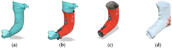
Figure 2.
(a) STL document of the filtered scanned arm in Fusion 360; (b) fulfilled orthosis (red) with structures with holes for screws designed over the scanned arm dimensions; (c) orthosis without an arm for future modifications; (d) manufactured orthosis without Voronoi diagram-based holes.
Finally, for the incorporation of the Voronoi holes we used the Voronoi Diagrams extension in Fusion 360 which automatically includes a plane with these patterns based on the imputed parameters. A diagram comprising 100 Voronoi holes with circular angles was selected, with regular spacing for the forearm section and minimum spacing for the biceps section; this was to evaluate the difference in performance under mechanical stress for each section. The holes were generated by projecting the diagram onto the orthosis, as seen in Figure 3.
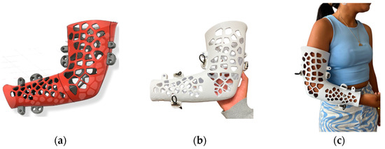
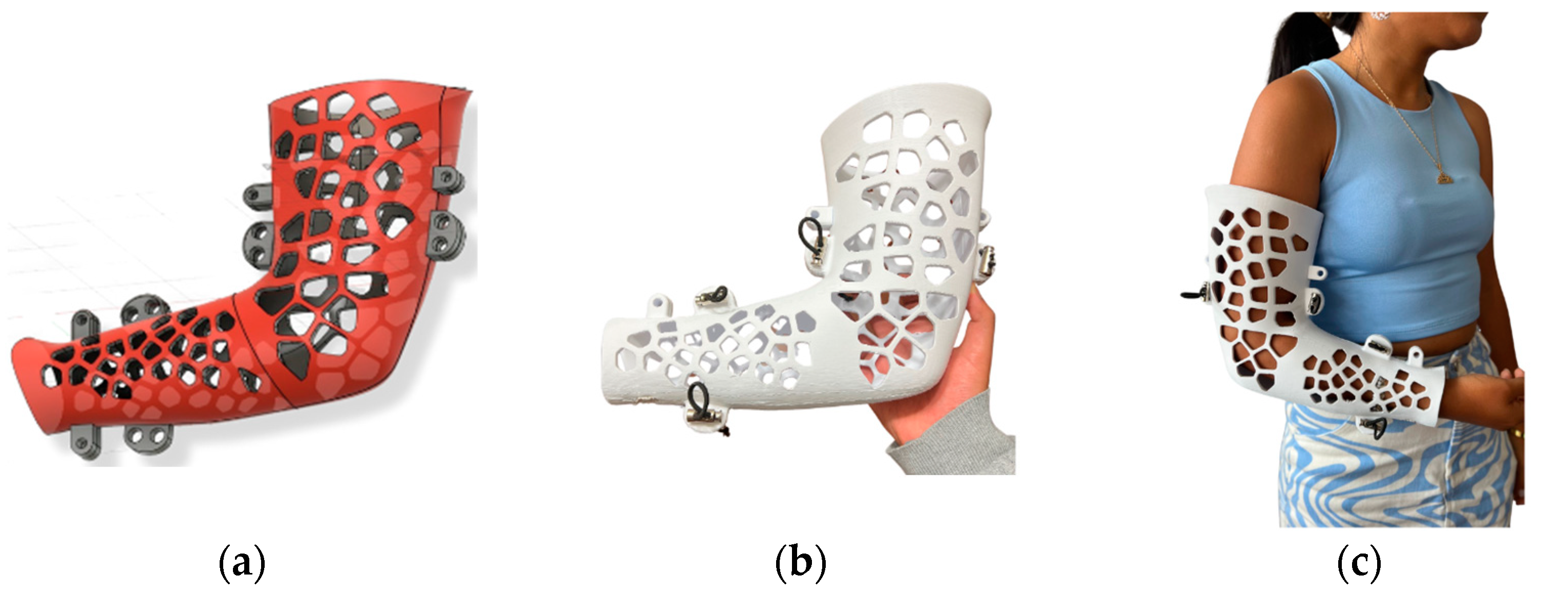
Figure 3.
(a) orthosis design with Voronoi diagram-based holes; (b) 3D-printed orthosis with Voronoi diagram-based holes; (c) patient wearing the manufactured orthosis.
Design of the Orthosis for Mechanical Testing
In order to obtain models suitable for mechanical evaluation, two variations of the orthosis were produced: one with holes and one without, both manufactured from PLA. Furthermore, a specialized coupling support, fabricated from mild steel, was designed to secure these components within the mechanical-testing machine. The orthosis designed specifically for mechanical testing included two couplings: The first coupling was located in the middle bicep region, where two screws can be placed and immobilize the orthosis to the support. The second coupling consists of a piece near the wrist section of the orthosis, designed to receive and concentrate the load generated by a punch during testing.
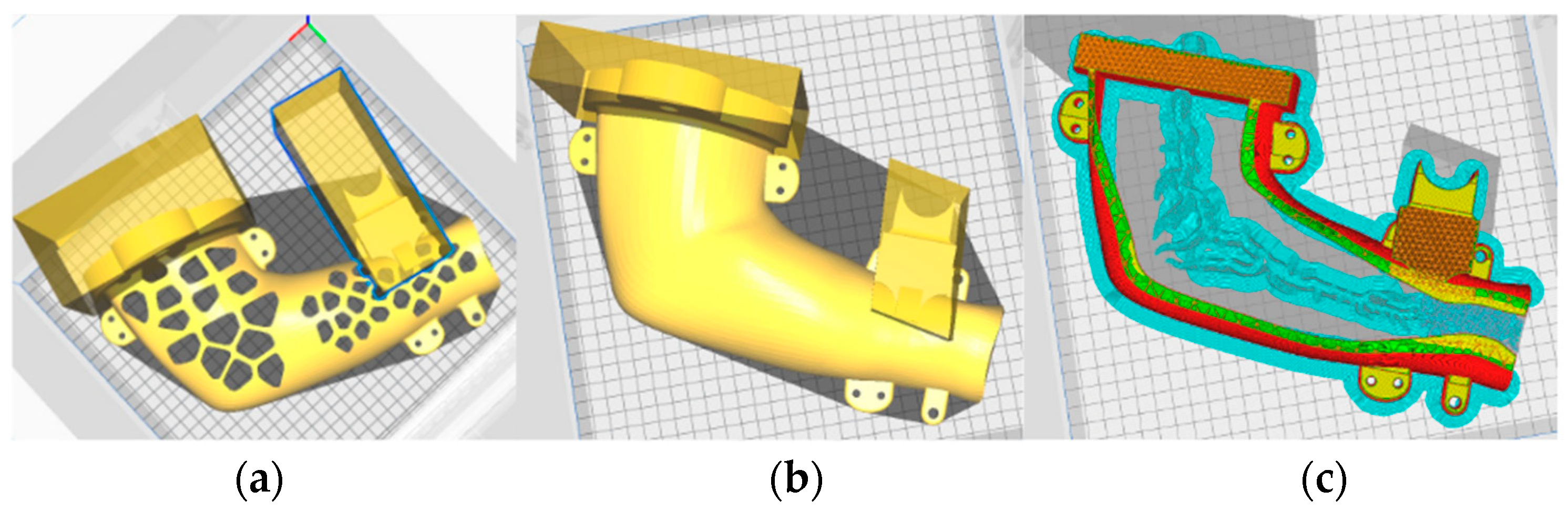
First, the original orthosis was segmented to facilitate the addition of the coupling for the support with two holes for the screws. Then, the punch section was individually designed, one by one and separated from the original file of the orthosis. These distinct components were assembled using Inventor, and then the files were exported in the STL format. Finally, the UltiMaker Cura software v.5.5 was employed to vary different densities to the coupling and punch section, ensuring they are rigid enough to hold mechanical stress. Figure 4 illustrates the slicing of the 3D model with different densities, carried out in UltiMaker Cura software.

Figure 4.
(a) Orthosis with holes modified to get different densities for printing (50% for the sections inside the parallelepipeds); (b) orthosis without holes modified to get different densities for printing (50% for the sections inside the parallelepipeds); (c) a piece sliced showing the different density of the coupling and awl section compared to the orthosis.
The orthoses were designed for the right arm, resulting in two pieces for each model—one internal and another external. The printed components are depicted in Figure 5.
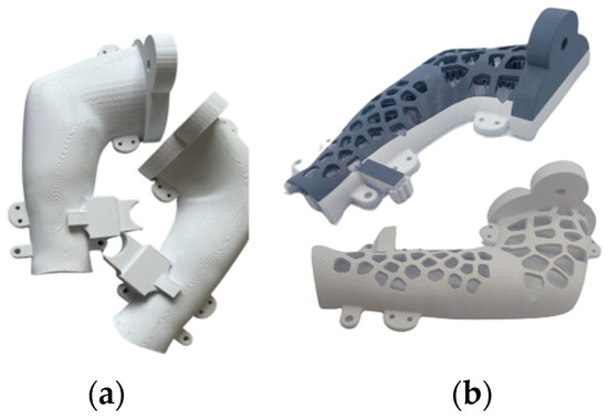
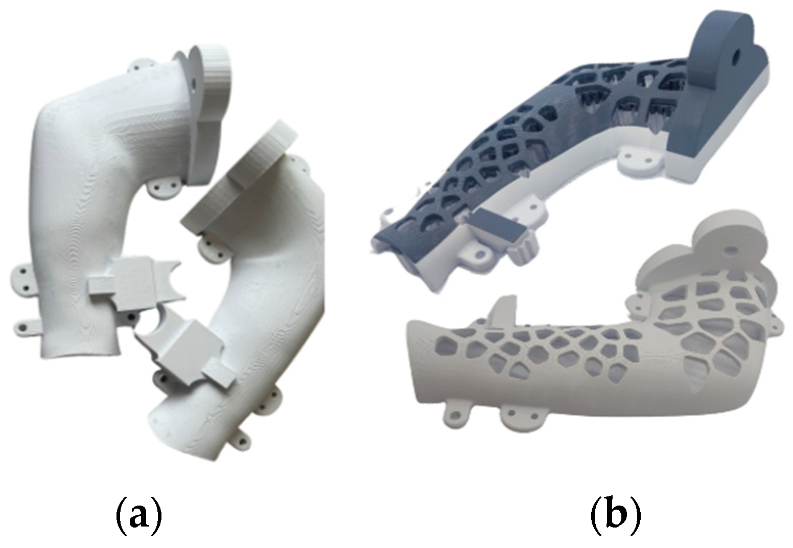
Figure 5.
(a) Orthosis with holes designed by Voronoi diagrams and (b) 3D-manufactured orthosis with Voronoi diagram-based holes.
2.5. Elbow Orthosis Manufacturing and 3D Printing
After the modeling was completed in Fusion 360, the parts were printed in the Artillery Sidewinder X1 of Core Facilities center (Fabcore) of the Pontificia Universidad Católica del Perú (PUCP). The parameters used in Ultimaker Cura and taken into account for the final modeling can be seen in Table 1. The printing lasted approximately 15 h for each piece (two per model). Consumption varied, with 262 g per piece for those with holes and 282 g per piece for those without holes. It should be noted that the values were chosen to reduce printing time as much as possible.

Table 1.
Parameters for the printing of the orthosis.
2.6. Mechanical Tests and Evaluations
Both orthosis designs, the one with holes and the one without, underwent a mechanical test evaluating bending resistance in the laboratory of materials “CITE Materiales”. For this test, a mild steel base was specifically designed to securely hold the orthosis in place, minimizing any significant deformations during the assessment. The base had regulations that allowed us to adjust the position of the testing orthosis with screws. This steel base with the fixed orthosis was then put into the Zwick/Roell Z050 universal testing machine (ZwickRoell GmbH, Ulm, Germany) where a load was applied on the exposed end of the orthosis at a rate of 5 mm/min using a testing punch of 30 mm of diameter.
3. Results and Discussion
3.1. Material Characterization
In this section, material characterization results of the PLA used for the orthosis are presented.
3.1.1. Tensile Test
The tensile test results of the 12 PLA specimens yielded an average Young Modulus of 2.9 GPa as the average of the specimens shows in Table 2. These findings align with the literature that establish the value of 2.9–3.3 GPa [20], as well as the manufacturer’s specifications. Therefore, we can conclude that it has a good property resistance.
Table 2.
Parameters for the printing of the flexion essay orthosis.
3.1.2. Simultaneous Thermal Analysis (STA)
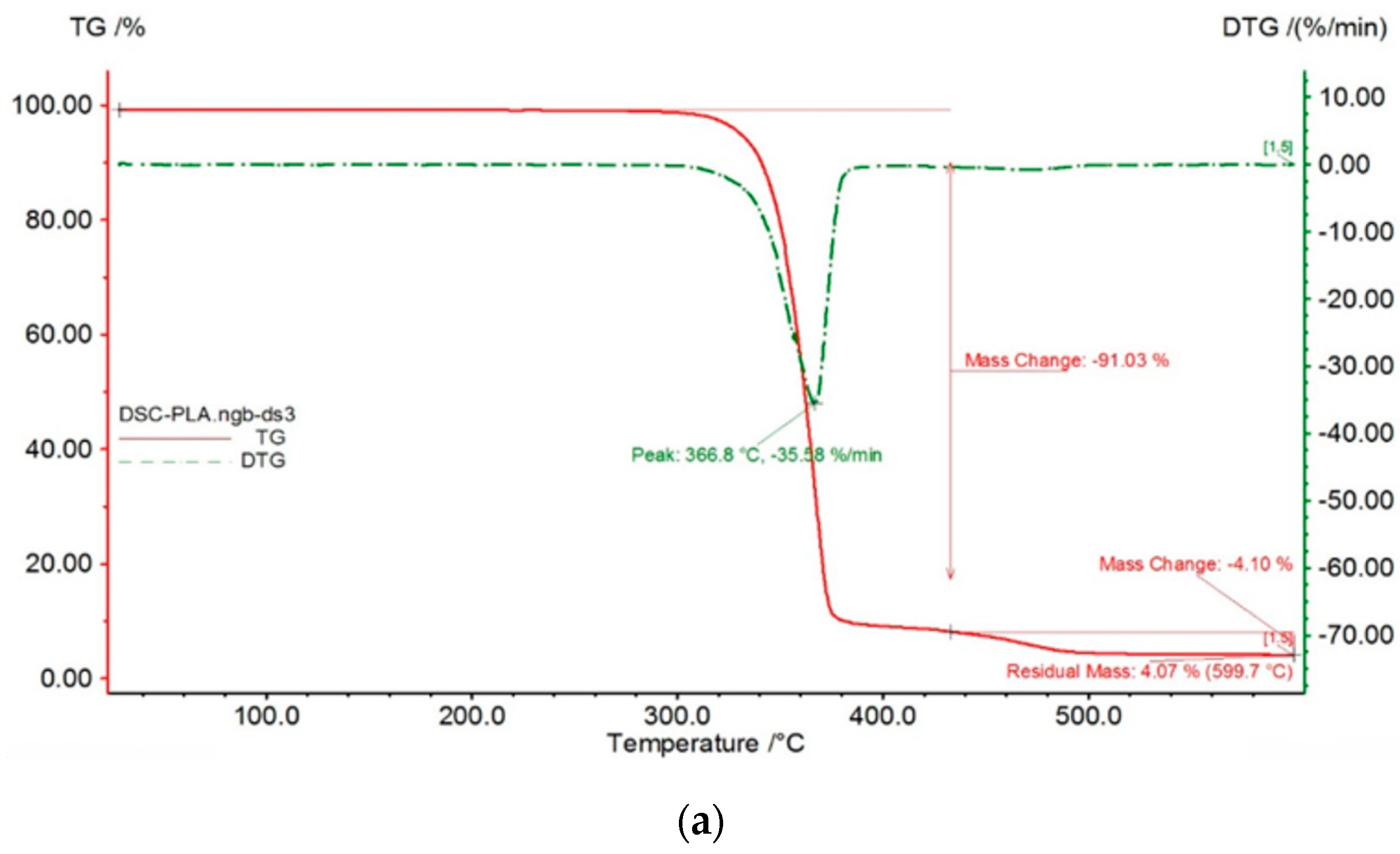
As shown in Figure 6a, The TG curve (red line) remains relatively flat from room temperature up to around 300°C, indicating good thermal stability in this range. There’s a slight initial mass loss, likely due to moisture or residual solvent evaporation. The derivative thermogravimetry curve (DTG), shown in a green dashed curve, shows a prominent peak at 366.8°C with a rate of mass loss of -35.58%/min. This peak corresponds to the temperature of maximum decomposition rate. The total mass loss associated with this primary degradation is approximately 91%.
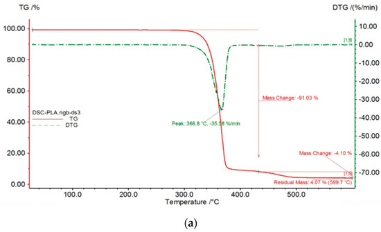
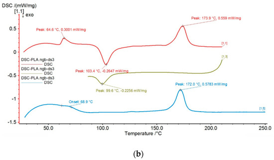
Figure 6.
Simultaneous thermal analysis results: (a). TG (red) and DTG (green dashed) curves showing the thermal degradation of the material. (b) DSC analysis.
On the other hand, Figure 6b shows the DSC plot with three curves plotted on the same graph, each representing a different scan repeated three times, with slightly different curve shapes and peak positions for each thermal transition. The green curve [13] exhibits a glass transition (Tg) at approximately 103.4 °C as an endothermic event. Exothermic crystallization events are observed at approximately 172.0 °C (blue curve [15]) and 173.9 °C (red curve [1.1]). These thermal transitions are important considerations for 3D printing since the extrusion temperature should be above the Tg (approximately 103.4 °C) to ensure proper flow.
3.2. Orthosis Results
In this section, mechanical test results from the orthosis with and without Voronoi diagram based-holes are presented.
Mechanical Tests That Evaluates the Flexion at 90 Degrees of the Orthosis
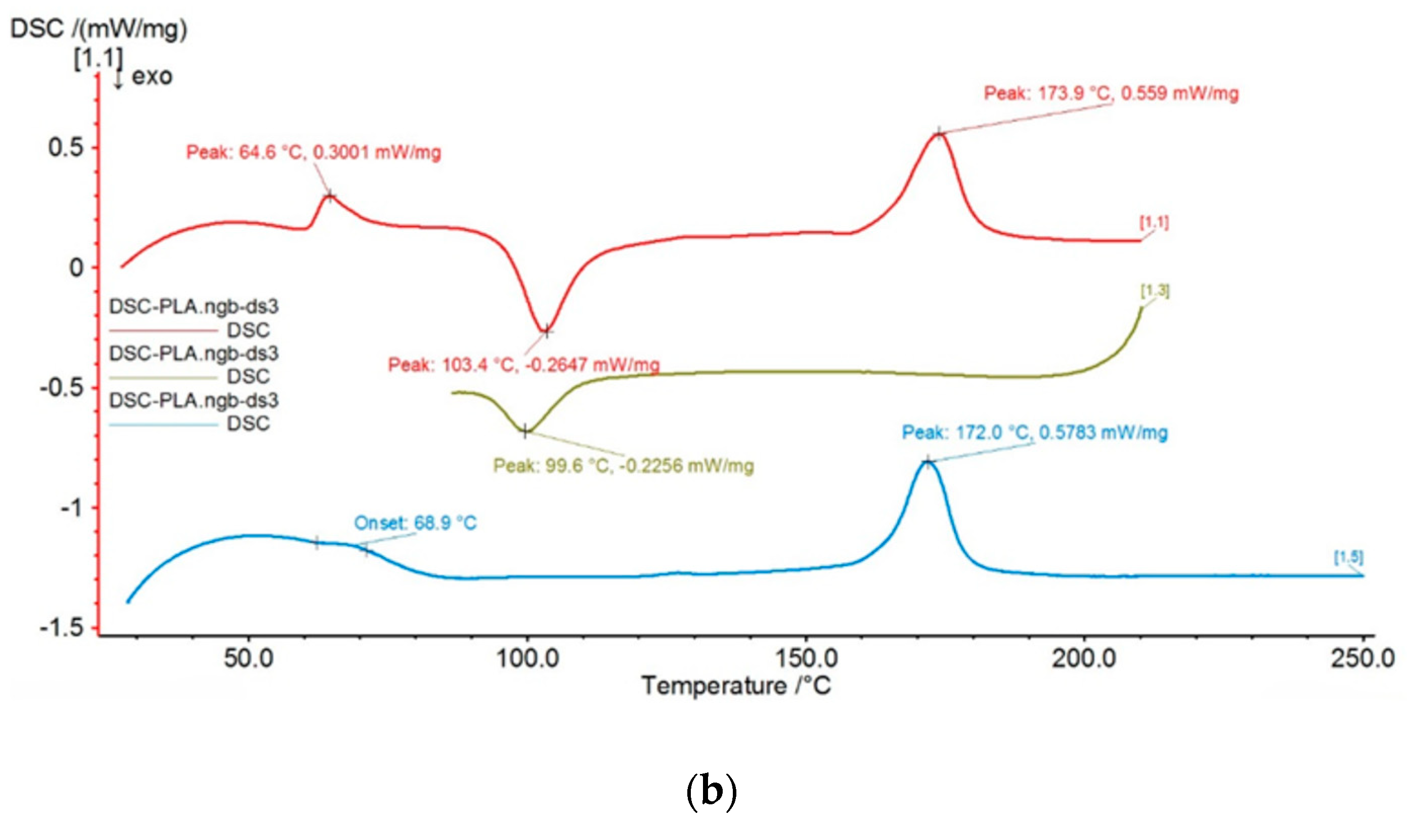
After performing mechanical tests on both the orthosis with and without Voronoi diagram based-holes as seen in Figure 7, the results are presented in Table 3.

Figure 7.
(a) Mild steel base and fixing screws; (b) 3D orthosis with Voronoi holes after fracture; (c) 3D orthosis without Voronoi holes after fracture.
Table 3.
Mechanical test results for orthosis with and without Voronoi holes.
It has been confirmed that both orthoses with and without holes can withstand loads well above the required minimum of 8 kg (the average weight of an arm). The orthosis with holes stands out with its significantly lighter weight. The included Voronoi holes not only enhance breathability but also contribute to a more effective distribution of forces, preventing the formation of stress-concentrated areas.
4. Conclusions
The development of this customized 3D-printed orthosis for the non-surgical treatment of olecranon elbow fractures presents a promising alternative to traditional surgical interventions. By utilizing 3D scanning, CAD software-based modeling, material characterization, and mechanical tests, a precise and stable immobilization solution following the VDI 2221 standard was achieved. The use of polylactic acid (PLA) as the material for the orthosis, characterized for its mechanical properties, thermal stability, and composition, demonstrated its suitability for this application. Mechanical tests, including a bending test, confirmed the orthosis’ performance under mechanical stress, with the incorporation of Voronoi holes which not only enhanced force distribution and mechanical performance but also made the orthosis breathable for optimal comfort during the recovery period. This innovative approach showcases the potential replicability of the customized 3D-printed orthosis not only for olecranon immobilization but also for other elbow injuries with similar treatment needs.
Author Contributions
Conceptualization, M.C. and D.R.; methodology, D.R., M.C., J.T. and C.B.; software, J.T., C.B. and D.R.; validation, A.R.M., G.C. and E.O.; formal analysis, A.R.M.; investigation, J.T., D.R., M.C. and C.B.; resources, A.R.M.; writing—original draft preparation, D.R., J.T., M.C. and C.B.; writing—review and editing, A.R.M., G.C. and E.O.; supervision, A.R.M., G.C.,and E.O. All authors have read and agreed to the published version of the manuscript.
Funding
This research received no external funding.
Institutional Review Board Statement
Not applicable.
Informed Consent Statement
Not applicable.
Data Availability Statement
All data produced in this study are included in the paper.
Acknowledgments
The authors would like to thank Core Facilities-FABCORE from Pontificia Universidad Católica del Perú.
Conflicts of Interest
The authors declare no conflicts of interest.
References
- Instituto Mexicano del Seguro Social. Coordinación de Unidades Médicas de alta Especialidad. Diagnóstico y Tratamiento de Lesiones Traumáticas de codo en Adultos. Available online: https://www.imss.gob.mx/sites/all/statics/guiasclinicas/198GE.pdf (accessed on 8 August 2023).
- Baecher, N.; Edwards, S. Olecranon fractures. J. Hand Surg. 2013, 38, 593–604. [Google Scholar] [CrossRef]
- Wiegand, L.; Bernstein, J.; Ahn, J. Fractures in brief: Olecranon fractures. Clin. Orthop. Relat. Res. 2012, 470, 3637–3641. [Google Scholar] [CrossRef] [PubMed]
- Jayakumar, P.; Teunis, T.; Vranceanu, A.M.; Moore, M.G.; Williams, M.; Lamb, S.; Ring, D.; Gwilym, S. Psychosocial factors affecting variation in patient-reported outcomes after elbow fractures. J. Shoulder Elb. Surg. 2019, 28, 1431–1440. [Google Scholar] [CrossRef]
- Sullivan, C.W.; Desai, K. Classifications in Brief: Mayo Classification of Olecranon Fractures. Clin. Orthop. Relat. Res. 2019, 477, 908–910. [Google Scholar] [CrossRef] [PubMed] [PubMed Central]
- Cantore, M.; Candela, V.; Sessa, P.; Giannicola, G.; Gumina, S. Epidemiology of isolated olecranon fractures: A detailed survey on a large sample of patients in a suburban area. JSES Int. 2022, 6, 309–314. [Google Scholar] [CrossRef] [PubMed]
- Bergström, J.S.; Hayman, D. An overview of mechanical properties and material modeling of polylactide (PLA) for medical applications. Ann. Biomed. Eng. 2016, 44, 330–340. [Google Scholar] [CrossRef] [PubMed]
- Sood, A.K.; Ohdar, R.K.; Mahapatra, S.S. Improving dimensional accuracy of fused deposition modelling processed part using grey Taguchi method. Mater. Des. 2010, 31, 2877–2884. [Google Scholar] [CrossRef]
- Gupta, A.; Kumar, A.; Kumar, V. A review on 3D printing materials and their sustainability. Mater. Today Proc. 2019, 18, 4379–4389. [Google Scholar]
- Hosford, W.F. Tensile Testing. In Mechanical Behavior of Materials; Cambridge University Press: Cambridge, UK, 2005; pp. 39–52. [Google Scholar]
- Differential Thermogravimetric Analysis. Available online: https://www.sciencedirect.com/topics/chemistry/differential-thermogravimetric-analysis (accessed on 1 December 2023).
- 3D Systems Support. Available online: https://support.3dsystems.com/s/article/Sense-Scanner?language=en_US (accessed on 9 December 2023).
- Voronoi Diagram. Voronoi Diagram—An Overview | ScienceDirect Topics. Available online: https://www.sciencedirect.com/topics/earth-and-planetary-sciences/voronoi-diagram (accessed on 3 December 2023).
- Voronoi Diagram from Wolfram MathWorld. Available online: https://mathworld.wolfram.com/VoronoiDiagram.html (accessed on 3 December 2023).
- Lau, C. The Voronoi theory of the normal liver lobular architecture and its applicability in hepatic zonation. Sci. Rep. 2021, 11, 9343. [Google Scholar] [CrossRef] [PubMed]
- Alknery, Z.; Sktani, Z.; Arab, A. Effect of cell geometry on the mechanical properties of 3D Voronoi tessellation. J. Funct. Biomater. 2022, 13, 302. [Google Scholar] [CrossRef]
- Zhao, H. Design and mechanical properties verification of gradient Voronoi scaffold for bone tissue engineering. Micromachines 2021, 12, 664. [Google Scholar] [CrossRef] [PubMed]
- Weydemann, L.; Clemenz, C.; Preisinger, C. On the structural properties of Voronoi diagrams. KoG 2021, 1, 72–77. [Google Scholar] [CrossRef]
- Ricotta, V.; Campbell, R.I.; Ingrassia, T.; Nigrelli, V. A new design approach for customized medical devices realized by additive manufacturing. Int. J. Interact. Des. Manuf. (IJIDeM) 2020, 14, 1171–1178. [Google Scholar] [CrossRef]
- PLA, Polylactic Acid, 3D Printing Filament, 1.75 mm Diameter. MatWeb Material Property Data. Available online: https://www.matweb.com/search/DataSheet.aspx?MatGUID=ab96a4c0655c4018a8785ac4031b9278&ckck=1 (accessed on 5 December 2023).

Disclaimer/Publisher’s Note: The statements, opinions and data contained in all publications are solely those of the individual author(s) and contributor(s) and not of MDPI and/or the editor(s). MDPI and/or the editor(s) disclaim responsibility for any injury to people or property resulting from any ideas, methods, instructions or products referred to in the content. |
© 2025 by the authors. Licensee MDPI, Basel, Switzerland. This article is an open access article distributed under the terms and conditions of the Creative Commons Attribution (CC BY) license (https://creativecommons.org/licenses/by/4.0/).