Proceeding Paper

Enhancing Voltage and Power Output Through the Structural Optimization of Coil–Magnet Transducers in Electromagnetic Vibration Energy Harvesters †

Department of Mechanical, Materials and Manufacturing Engineering, University of Nottingham Ningbo China, Ningbo 315100, China
*
Author to whom correspondence should be addressed.
Presented at The 11th International Electronic Conference on Sensors and Applications (ECSA-11), 26–28 November 2024; Available online: https://sciforum.net/event/ecsa-11.
Eng. Proc. 2024, 82(1), 105; https://doi.org/10.3390/ecsa-11-20405
Published: 25 November 2024

Abstract

:
Electromagnetic vibration energy harvesters (EVEHs) have emerged as a promising approach to powering small electronic devices and sensors, particularly in remote or inaccessible locations where traditional power sources are impractical. This study investigates approaches for structurally scaling and optimizing the EVEH transducer magnet structure to maximize the magnet flux density, total flux density, harvested voltages and power output. Six design configurations have been analyzed in different coils and transducer magnet/flux guiding steel geometries. While the coil varies by using bulk or split coils, the magnet/flux guiding steel is varied by using different sizes. Analytical validation and simulations showed that these variations generally affected the transducer flux density per unit magnet volume β V m a g and total volume β V T o t . Validation shows that configurations with a split center magnet with the smallest transducer volume attains preferable β V m a g ,   β V T o t and power density by approximately 21.66%, 15.77% and 54.47% over the reference model without center magnet/steel. Therefore, the most structurally optimized configuration attained a light weight but a higher energy conversion/flux coupling efficiency. Also, the analysis showed that using split slotted coils is more efficient for energy harvesting than using bulk equivalent (single) coils counterparts. This is because the split coil will encourage more flux coupling than bulk coil. Additionally, the optimal load capacity is considerably reduced by approximately 50.00% on configurations with split coil. Therefore, split and bulk are respectively suitable for low- and high-impedance matching.

1. Introduction

Vibration energy harvesting has emerged as an effective approach to powering small electronic devices and sensors, particularly in remote or inaccessible locations where traditional power sources are impractical [1]. Among the various transducer mechanisms, electromagnetic vibration energy harvesters (EVEHs) have garnered significant attention due to their relatively simple design, high energy conversion efficiency and scalability [2,3]. Generally, the performance of EVEHs is heavily dependent on the structural configuration and relative positioning of the magnets and coils within the transducer [4,5]. Numerous studies have investigated strategies for optimizing the EVEH design and enhancing its power output. Saha et al. [6] analyzed the effect of the magnet–coil gap on the voltage and power generation and reported an optimal gap distance for maximum performance. Similarly, Zhu et al. [7] explored the influence of the coil position and found that an off-center coil configuration can improve the EVEH’s power density. In addition to the magnet–coil arrangement, the magnetic flux density within the transducer also plays a crucial role in determining the EVEH’s performance [8,9]. Researchers have proposed various techniques for optimizing the magnetic circuit, such as utilizing Halbach arrays [10] or incorporating flux-concentrating elements [11], to maximize the magnetic flux linkage and, consequently, the harvested power. Recent advancements in computational modeling and simulation have enabled the more comprehensive optimization of EVEH structures. Analytical models have been developed to predict the open-circuit voltage and power output, which are then validated through experimental measurements on prototype systems [12,13]. These models provide a powerful tool for exploring the design space and identifying optimal configurations that can significantly enhance the EVEH’s performance. Several studies have demonstrated the effectiveness of structural optimization in improving the voltage and power output of EVEHs. Tao et al. [14] reported a 35% increase in power output by optimizing the magnet and coil positions. Deng et al. [15] introduced a multi-magnet EVEH design that achieved a 40% improvement in power density compared to a single-magnet configuration. Similarly, Xie et al. [16] proposed a segmented magnet arrangement that enhanced the EVEH’s power output by up to 50%. The continued research and development in this field have led to the emergence of various advanced EVEH designs, such as those incorporating magnetic levitation [17], flux feedback mechanisms in the harvester magnet transducer [18] and hybrid transducer mechanisms [19]. These innovations aim to further improve the energy-harvesting capabilities and expand the applicability of EVEHs in powering a wide range of self-powered and sustainable electronics.
In summary, the optimization of EVEH structures by strategically positioning the magnets and coils has been a major focus of research in recent years. The literature demonstrates that significant improvements in the harvested voltages and power can be achieved through comprehensive parametric analysis and optimization. The findings from these studies provide valuable insights for the design and implementation of high-performance EVEHs, contributing to the advancement of self-powered and sustainable electronic systems.

2. Governing Equation of a Spring-Mass Model

To effectively generalize the equation that governs the electromagnetic vibration energy harvester (EVEH) whose transducer coil-magnet properties are to be structurally optimized for improved performances, the EVEH is shown as a spring-mass model, as shown in Figure 1. The general equation that governs the responses of the model in Figure 1 is shown in Equation (1):
m e Y ¨ t + 2 m e ζ e q ω n Y ˙ t + k Y t + F r s g n Y ˙ = m e ω 2 F c o s ω t + φ
In Figure 1, m e ,   k ,   ω ,   ω n ,   ζ e q ,   F ,   φ ,   F r and Y ( t ) are the model effective mass, linear stiffness, excitation frequency, resonance frequency, total damping ratio in the system, excitation amplitude, phase shift between the excitation and the mass displacement, Coulomb friction force in the system and response amplitude in the temporal coordinates. The total damping ratio in the system ( ζ e q ) is defined as the linear summation of the damping contributions from the mechanical ( ζ m ) and electromagnetic ( ζ e m ) loss components.
This study investigates how the EVEH magnet structure could maximize the flux densities per magnet volume, harvested voltages and power output by a comparative study using three (3) design scenarios. When vibration is induced in the spring mass model of Figure 1, the mass (magnet) mounted on the spring will oscillate, and therefore voltage will be induced in the transducer coil as it cuts through the fields of the spring-mounted permanent magnets or vice versa. As the coil interacts with the permanent magnet field in a steady and continuous periodic motion, voltage is induced. The induced voltage is computed using the Faraday principle of electromagnetic induction. The steady state relative and absolute amplitude solution of the spring mass (coil) model for each i t h configuration are obtained as shown in Equations (2) and (3), with   i = a ,   b and c:
Y i = G i F r i K + F Q i 2 r i 4 H i F r i K 2
X i = Y i 2 + F 0 2 + 2 F 0 Y i c o s φ i
where k is the spring stiffness, r is the frequency ratio and other parameters in Equations (2) and (3) are listed in the appendix section and defined, as shown in Appendix A. Likewise, the total damping ratio ( ζ e q i ) components for each i t h transducer configuration are shown in Equations (4) and (5), where c m i is the springs mechanical damping constant.
ζ m i = c m i 2 m e i ω i
ζ e m i = 8 K i 2 l c i 2 2 m e i ω i 1 R l i + R c i
K i = N i b i C f i l c i
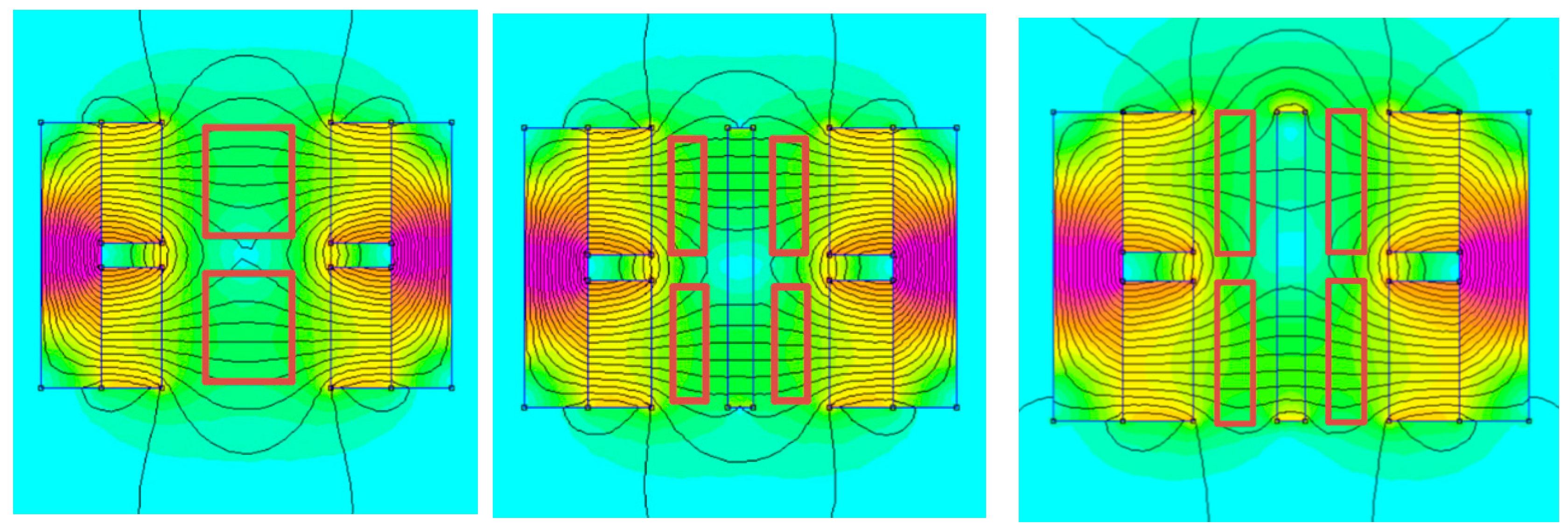
To complete a close circuit for voltage/power harvesting, it is required that the harvester model is connected over an external load resistor, as shown in Figure 1. When the transducer coil with internal resistance ( R c i ) is connected over an external load having a resistance R l i , for each i t h configuration, N i ,   b i ,   C f i , and l c i are the transducer coil turn number, coupling coefficient, external load resistance, internal resistance of the coil and effective coil length. The coupling coefficient K i is defined as the number of the flux line that cuts the coil, as shown in Equation (6). The average flux density induced in the regions of the i t h coil was simulated on the Finite Element Magnetic Method (FEMM) software, as shown in Figure 2 and Figure 3. Also, the expression for the harvester voltage and power harvested over the R l for each i t h configuration is obtained as shown in Equations (7) and (8), respectively, where   i = a ,   b , and c.
V i = 4 K i l c i Y i ω i R l i R l i + R c i
P i = 16 K i 2 l c i 2 Y i 2 ω i 2 R l i R l i + R c i 2
The determination of the model’s optimal load was achieved using the maximum power transfer theorem, which stipulates that the rate of change of output power with respect to load resistance δ P O u t δ R l = 0 . This derivative yields an expression for the optimal load resistance R l o p t , as indicated in Equation (9), where c i represents the mechanical damping coefficient.
R l o p t = 16 K i 2 l c i 2 c m i + R c i

3. Transducer Coil–Magnet Models

To investigate different optimization strategies for the coil–magnet transducer geometries, the analyzed design models ‘a’, ‘b’ and ‘c’ are shown in Figure 2.
In the following analysis, each of the models refers to configurations a, b, and c, respectively, where configuration ‘a’ is the reference. In Figure 2, h s ,   h a and h m are the heights of the flux guiding steel, transducer magnet/coils air gap and transducer magnets. Also, c w ,   w m ,   w c and w s are the coil width, width of the transducer magnets, width of the center circuit splitting material (magnet/iron) and width of the flux guiding steel, respectively. For simplicity and effective comparison of the respective designs, the minimum clearance distance which ensures that there is not dynamic contact between the coil and the magnet during dynamic operation is fixated at c d = 0.875 mm and h a is also fixed at 2.00 mm for all. In Figure 2, configuration ‘a’ is the reference model using a bulk no-split coil. Also, configurations b1 and b2 use continuous steel and magnet material at the center, respectively, to achieve split coil slots with flux guiding steel. However, to maximize the structural geometrical variations in the configurations ‘c’, it is further simplified into a total of three (3) design variations: ‘c1’, ‘c2’ and ‘c3’. Configurations ‘c1’, and ‘c2’ are respectively defined as using split steel and magnet material at the center to achieve split coil slots without outer flux guiding steel, while ‘c3’ uses a split magnet material at the center to achieve split coil slots with outer flux guiding steel. The respective values of h s ,   h m ,   c w ,   w m and w s for the design configurationa ‘a’, ‘b1’, ‘b2’, ‘c1’, ‘c2’ and ‘c3’ are shown in Table 1.
For each configuration, the effective total volume V T o t and effective magnet volume V m are computed. While V T o t represents the total volume of the transducer model, V m is defined as the total magnet volume in the model designs. Likewise, when the flux density in the area occupied by the transduction coil is measured as b , the flux density per total volume β V T o t and the flux density per magnet volume β m a g is computed as the parameter for quantifying the design parameters.

4. Finite Element Magnetic Method (FEMM) Simulation

This section clearly reports the method for quantifying the flux within the coil region in the transducer geometry in brief. The respective FEMM results for the different geometries are shown in Figure 3 and Figure 4.
In Figure 3 and Figure 4, the red highlight portion is used to define the location of the coil in static equilibrium. During dynamic operation (energy harvesting), the coil begins to oscillate in the field of the permanent magnet. This oscillation therefore resulted in voltages being induced in the coil.
The respective values of the flux densities in the region where the coil oscillates during energy harvesting are measured and recorded in Table 2.

5. Results and Parametric Analysis

This section investigated and quantified how the structural optimization of the coil–magnet transducer shown in Figure 2 enhanced or compromised the spring-mass EVEH voltage and power output. To complete a close circuit for voltage/power harvesting, it is required that the harvester model is connected over an external load resistor, as shown in Figure 1. The respective equations for computing the harvested voltages and power are given in Equations (7) and (8), while Equation (9) shows the value of the resistance at which the external load becomes optimized. This stage of analysis shall be undertaken in two stages. The first stages shall focus on characterizing which design configuration is most proficient for applications in term of b ,   β m a g and   β V T o t . Using the appropriate power equation, the second stage of the analysis shall investigate the relative harvestable power/voltage performances. Finally, the conclusion part of this report will identify the relevant performance preference as a consequences of the initial stages of the analysis.
  • b ,   β m a g and   β V T o t variation: This stage of analysis briefly illustrates the variations in b ,   β m a g and   β V T o t as a function of the transducer geometrical volume. The flux density per unit volume of the transducer is independently compared as a ratio of total volume and magnet volumes, as shown in Table 2. Table 2 shows that although configuration a1 has the largest b , β m a g for configuration c3 is improved by approximately 21.66%, 31.64%, 38.92%, 43.72% and 31.40%, respectively, relative to configurations a1, b1, b2, c1 and c2. Also, the β V T o t for configuration c3 is improved by 15.77%, 13.39%, 28.17%, 5.93% and 13.38%, respectively, relative to configurations a1, b1, b2, c1 and c2. Therefore, configuration c3 was identified to attain this preferential density value at the smallest magnet and a total volume of 0.3750 × 10 5   m 3 and 1.3200 × 10 5   m 3 compared to others. This suggests that c3 is good enough to represent the improvement in the β m a g by approximately 30.00% over other configurations. As shown in the next section, this improvement will definitely result in the efficient utilization of the available magnet flux/magnet volume to induce and enhance the operational efficiency of the system.
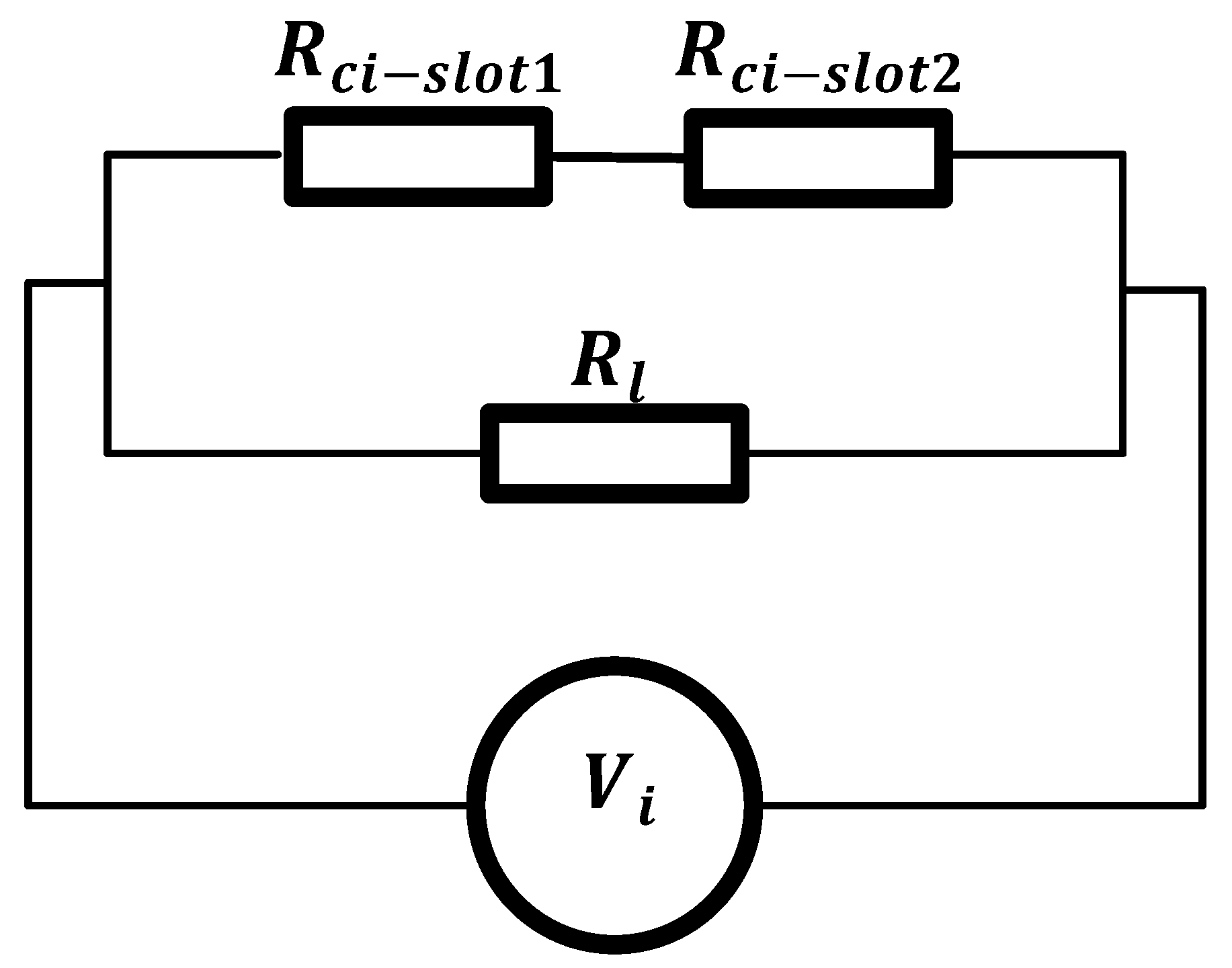
  • V i and P i variation: This stage of analysis briefly illustrated the variations in the harvested voltages and power as a function of different electrical parameters. Using configuration 1, which has an 8 mm coil width as the reference, configurations 2, 3, 4, 5 and 6, however, use two split 4 mm in the double slot sections of the transducer. To characterize this variation, the coil in each slot point is connected to external load resistances, as shown in Figure 5.
For configuration 1, having only one slot coil, Figure 5 reduces by eliminating coil slot 2 and corresponding electrical parameters. The analytical formulations in the above procedure demand that the cumulated power performance comparison for each model is accurately comparable by lump summing the voltage and power on the series connected split coils shown in Figure 5 for configurations 2 to 6 according to Ohm’s law. Ohm’s law asserts that when two voltage sources are connected in series, the effective voltage is the summation of the respective voltage in each source. Using Ohm’s condition, the effective resistance on each coil is therefore obtained, as shown in Equation (10).
R T = R c i s l o t 1 + R c i s l o t 2 + R l
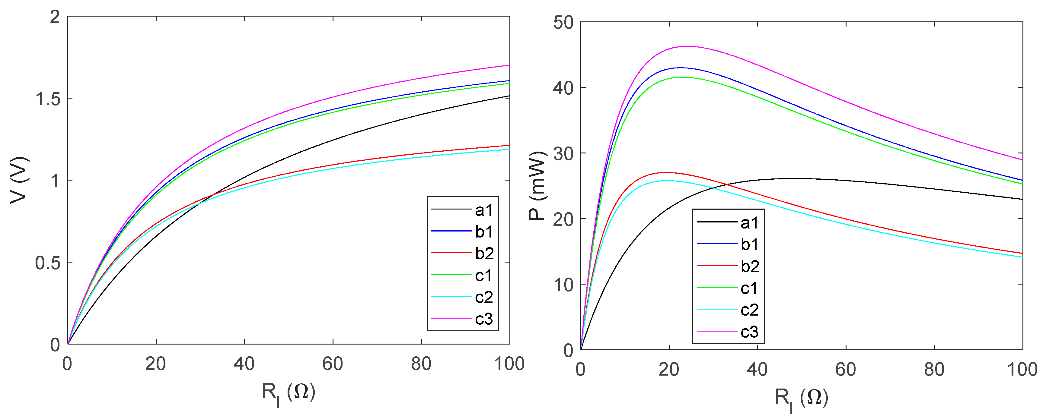
Using Equation (9), Figure 6 (left) and Figure 6 (right) show that the power becomes maximized at optimal resistance values of 48.30 Ω , 22.00 Ω , 18.80 Ω , 23.00 Ω , 19.30 Ω and 24.40 Ω , respectively, on slotted coils 1 to 6.
The effective coil length l c = 2 π r e , where r e is the effective coil radius and l c = 72.571 mm for configurations 1 to 6. The relevant coil parameter for each slotted coil in each configuration is shown in Table 3, where the coil turn for each split coil is 500.
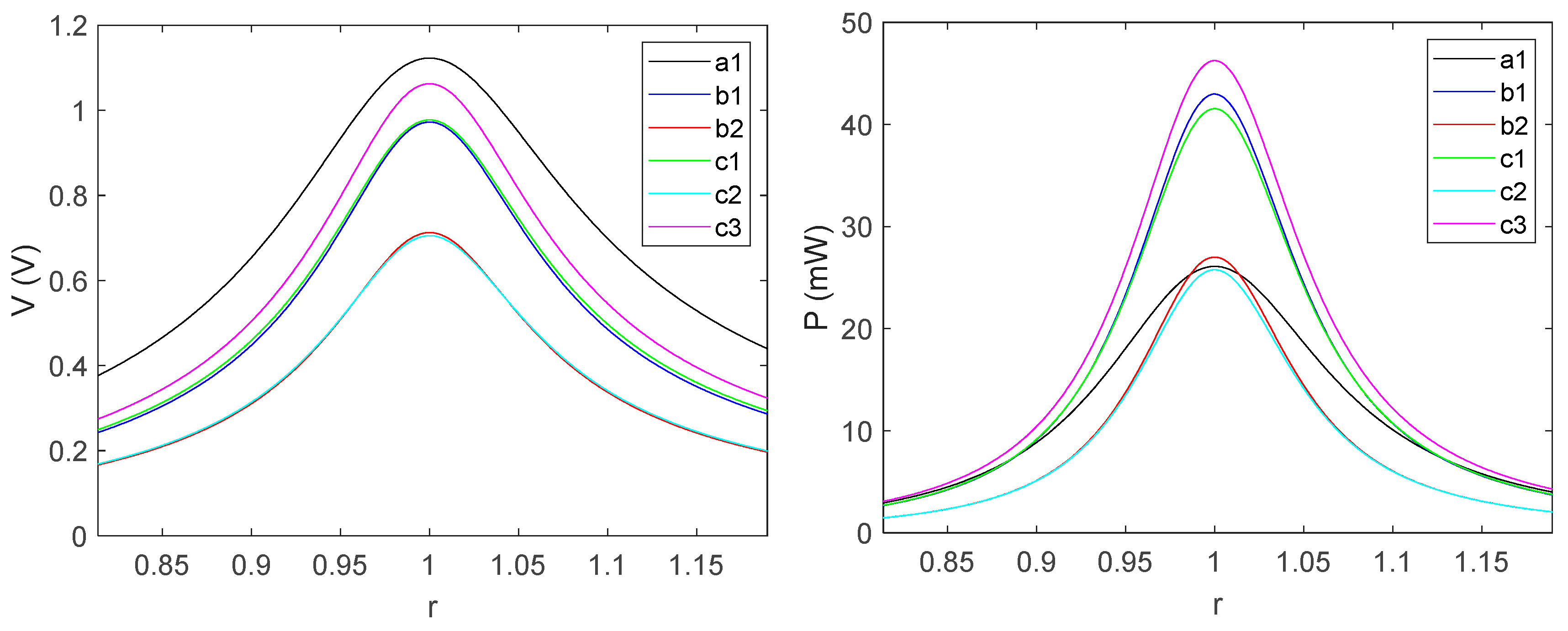
r is the frequency ratio of the system, and Figure 7 shows the variation in the harvested voltage and power at optimum. Comparing Figure 7, Table 2 and Table 3 show that although configuration 1 (8 mm) attains the highest possible flux density, the optimum characteristics showed that its optimum harvested resonant power is compromised by approximately 43.57%, 37.17%, 3.37% and 39.69% relative to configurations c3, c1, b2 and b1, respectively. Conversely, the resonant optimum output of a1 is preferable by 12.57% over c2.
Therefore, Figure 7 establishes a generalized trend for quantifying the power variation of the different configurations. Figure 7 further highlights the observation made in the section, where b ,   β m a g and β V T o t variation was undertaken. Configuration c3 was identified to efficiently utilize the available magnet volume to induce and enhance the operational efficiency of the system by harvesting the highest possible power at equivalent excitation and optimal load comparisons.

6. Conclusions

The following conclusions are reached in this work:
  • A transducer model configuration with the smallest volume c 3 attained the highest possible flux density per transducer magnet volume.
  • Although flux guiding steel, which minimizes flux leakages, is often required to enhance flux coupling, configuration c2, which has no such guiding steel, shows a satisfactory performance next to c3 in terms of flux density per unit magnet/total volume, optimum load, harvested voltages and power. The implication of this is that smaller-volume, lightweight but efficient energy conversion/flux coupling is attainable in c3.
  • The analysis showed that using split-slotted coils is more efficient for energy harvesting than using bulk single-equivalent coils. This is because the split coil will encourage more flux coupling/field interaction with the coil than bulk coil.
  • The implication of the above implies that while larger power is available for harvesting over a series connected split coil than for the bulk coil, the optimal load capacity is considerably reduced by approximately 50.00%. Therefore, for efficient energy conversion and maximized power applicability, the series connected split coils boast usability for low-impedance systems, while bulk coil is suitable for high-impedance matching.

Author Contributions

Conceptualization, C.K.T.; methodology, C.K.T., T.T.; software, T.T.; validation, T.T.; formal analysis, T.T.; investigation, T.T.; resources, C.K.T.; data curation, C.K.T.; writing—original draft preparation, T.T.; writing—review and editing, C.K.T.; visualization, T.T.; supervision, C.K.T.; project administration, C.K.T. All authors have read and agreed to the published version of the manuscript.

Funding

This research received no external funding.

Institutional Review Board Statement

Not applicable.

Informed Consent Statement

Not applicable.

Data Availability Statement

The data presented in this study are available upon request from the corresponding author.

Conflicts of Interest

The authors declare no conflicts of interest.

Appendix A

r i = w w n i ,   τ i = π ζ e q i 2 + 1 r i ,   λ i = π ζ e q i r i ,   G i = sinh λ i ζ e q i 1 ζ e q i 2 s i n ( τ i ) cosh λ i + c o s ( τ i )
H i = 1 r i 1 ζ e q i 2 ζ e q i 1 ζ e q i 2 sin τ i cosh λ i + cos τ i ,   Q i = 1 ( ω n i 2 ω 2 ) 2 + 2 ζ e q i w n i 2 1 2
φ i = t a n 1 2 ζ e q i r i 1 r i 2 ,   w n i = k m e i
where Q i ,   G i and H i are regarded as the viscous and transfer functions.

References

  1. Priya, S.; Inman, D.J. Energy Harvesting Technologies; Springer: Berlin/Heidelberg, Germany, 2009. [Google Scholar]
  2. Beeby, S.P.; Tudor, M.J.; White, N.M. Energy harvesting vibration sources for microsystems applications. Meas. Sci. Technol. 2006, 17, R175–R195. [Google Scholar] [CrossRef]
  3. Mitcheson, P.D.; Yeatman, E.M.; Rao, G.K.; Holmes, A.S.; Green, T.C. Energy Harvesting From Human and Machine Motion for Wireless Electronic Devices. Proc. IEEE 2008, 96, 1457–1486. [Google Scholar] [CrossRef]
  4. Elvin, N.G.; Erturk, A.A. Advances in Energy Harvesting Methods; Springer: Berlin/Heidelberg, Germany, 2013. [Google Scholar]
  5. Toluwaloju, T.I.; Thein, C.K.; Halim, D. A parametric analysis on performance dependence of electromagnetic vibration harvester on the coil position, coil connection, and magnetic flux density. In Proceedings of the 2022 International Conference on Electrical, Computer, Communications and Mechatronics Engineering (ICECCME), Maldives, 16–18 November 2022; pp. 1–6. [Google Scholar]
  6. Saha, C.R.; O’Donnell, T.; Wang, N.; McCloskey, P. Electromagnetic generator for harvesting energy from human motion. Sens. Actuators A Phys. 2008, 147, 248–253. [Google Scholar]
  7. Zhu, D.; Roberts, S.; Tudor, M.J.; Beeby, S.P. Design and experimental characterization of a tunable vibration-based electromagnetic micro-generator. Sens. Actuators A Phys. 2010, 158, 284–293. [Google Scholar] [CrossRef]
  8. Shu, Y.; Lien, I.; Wu, W. An improved analysis of the performance of a piezoelectric energy harvester. Smart Mater. Struct. 2007, 16, 2253–2264. [Google Scholar] [CrossRef]
  9. Toluwaloju, T.I.; Yadav, D.; Thein, C.K.; Halim, D. Investigation on the effect of magnetic coupling and power harvested in an electromagnetic vibration energy harvester. In Proceedings of the 2022 IEEE International Conference on Industrial Technology (ICIT), Shanghai, China, 22–25 August 2022; pp. 1–6. [Google Scholar]
  10. Zhu, D.; Beeby, S.P.; Tudor, M.J.; Harris, N.R. Electromagnetic Vibration Energy Harvesting using an Improved Halbach Array. Smart Mater. Struct. 2012, 20, 022001. [Google Scholar]
  11. Priya, S. Advances in energy harvesting using low profile piezoelectric transducers. J. Electroceram. 2007, 19, 165–182. [Google Scholar] [CrossRef]
  12. Adhikari, S.; Friswell, M.I.; Inman, D.J. Piezoelectric energy harvesting from broadband random vibrations. Smart Mater. Struct. 2009, 18, 115005. [Google Scholar] [CrossRef]
  13. Foong, F.M.; Thein, C.K.; Yurchenko, D. A two-stage electromagnetic coupling and structural optimization for vibration energy harvesters. Smart Mater. Struct. 2020, 29, 085002. [Google Scholar]
  14. Tao, K.; Tang, L.; Wu, J.; Lye, S.W.; Chang, H.; Miao, J. Investigation of multimodal electret-based MEMS energy harvester with impact-induced nonlinearity. J. Microelectromech. Syst. 2018, 27, 276–288. [Google Scholar]
  15. Deng, Q.; Liu, Y.; Ci, L. A multi-magnet vibration energy harvester using ferromagnetic yokes to increase the power density. Appl. Energy 2017, 208, 1246–1253. [Google Scholar]
  16. Xie, L.; Cai, Y.; Dai, Q. A segmented magnet design for improved performance of linear electromagnetic vibration energy harvester. Mech. Syst. Signal Process. 2019, 127, 523–537. [Google Scholar]
  17. Zhou, S.; Cao, J.; Erturk, A.; Lin, J. Enhanced broadband piezoelectric energy harvesting using rotatable magnets. Appl. Phys. Lett. 2013, 102, 173901. [Google Scholar] [CrossRef]
  18. Toluwaloju, T.I.; Thein, C.K.; Halim, D. Flux feedback mechanism for realizing enhanced flux density in an electromagnetic vibration energy harvester. In Proceedings of the 2023 3rd International Conference on Electrical, Computer, Communications and Mechatronics Engineering (ICECCME), Tenerife, Canary Islands, Spain, 19–21 July 2023; pp. 1–6. [Google Scholar]
  19. Peng, W.; Ni, Q.; Zhu, R.; Fu, X.; Zhu, X.; Zhang, C.; Liao, L. Triboelectric-electromagnetic hybrid wind energy harvesting and multifunctional sensing device for self-powered smart agricultural monitoring. Nano Energy 2024, 131, 110272. [Google Scholar] [CrossRef]
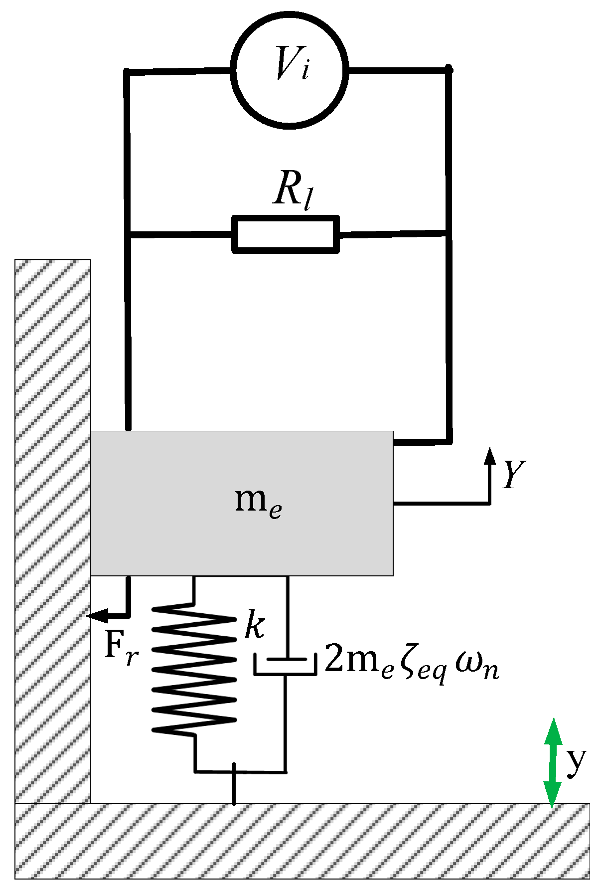
Figure 1. Spring mass model of the EVEH.
Engproc 82 00105 g001
Figure 2. Configuration a: transducer coil–magnet models; single-slotted coil–four magnets circuit (left), Configuration b: double-slotted coils–split magnet circuit with conductive steel in the center (middle) and Configuration c: double-slotted coils with split conductive magnet/steel in the center (right).
Engproc 82 00105 g002
Figure 3. FEMM simulation configurations a (left), b1 (middle) and b2 (right).
Engproc 82 00105 g003
Figure 4. FEMM simulation configurations c1 (left), c2 (middle) and c3 (right).
Engproc 82 00105 g004
Figure 5. Generalized closed circuit connection of the VEH.
Engproc 82 00105 g005
Figure 6. Harvested voltage (left) and power (right) versus R l .
Engproc 82 00105 g006
Figure 7. Harvested voltage (left) and power (right) at R l i o p t .
Engproc 82 00105 g007
Table 1. Summary of magnet dimensions for transducer models 1, 2 and 3.
Configurationi h s   ( m m ) h a   ( m m ) h m   ( m m ) c w   ( m m ) w m   ( m m ) w s   ( m m ) w c   ( m m )
a122.002.0010.008.005.005.000.00
b122.002.0010.004.005.005.002.50
222.002.0010.004.005.005.002.50
c122.002.0010.004.005.000.002.50
222.002.0010.004.002.500.002.50
322.002.0010.004.002.502.502.50
Table 2. Summary of magnetic flux densities   V m a g ,   V T o t ,   β m a g and β V T o t for models 1, 2 and 3.
Config.
D m m m
b (T)
V m a g × 10 5 m 3
V T o t × 10 5 m 3
β m a g × 10 4 T m 3
β V T o t × 10 4 T m 3
a19.7500.3820.50001.63627.64582.3364
b114.0000.3320.50001.87006.67181.7890
b214.0000.2440.62501.87005.96111.9923
c114.0000.3430.62501.32005.49312.6092
c214.0000.2510.37501.04506.69502.4025
c314.0000.3680.37501.32009.75982.7737
Table 3. Summary of optimum parameters for transducer models.
Config.a1b1b2c1c2c3
R l i o p t ( Ω ) 48.30022.00018.80023.00019.30024.400
P i o p t ( m W ) 26.10242.98027.01241.54325.77446.255
Disclaimer/Publisher’s Note: The statements, opinions and data contained in all publications are solely those of the individual author(s) and contributor(s) and not of MDPI and/or the editor(s). MDPI and/or the editor(s) disclaim responsibility for any injury to people or property resulting from any ideas, methods, instructions or products referred to in the content.