Abstract
Internal corrosion in pipelines is the most critical factor for pipeline failure. The growing trend of mitigating internal corrosion in pipelines by using nanofiber polymer composite liners was investigated in this study. The liners were fabricated using the electrospun Polyacrylonitrile (PAN) and graphite-doped PAN nanofibers. The liners were tested by immersing in water at 23 °C, 50 °C, and light oil to determine the diffusion characteristics. The absorption results combined with ATR-FTIR results confirmed that the addition of graphite-doped nanofibers has controlled the absorption significantly.
1. Introduction
Pipeline transportation involves the movement of solid, liquid, and gas over long distances and is widely used for oil, natural gas, and CO2 transportation, as well as other fluids such as water, slurry, sewage, etc. [1]. Pipelines are excellent for single-directional flow, and are economical, rapid, continuous, high-capacity, reliable, and low-investment [2]. However, the failure of pipelines can be catastrophic, resulting in environmental damage, loss of life, production stoppage, and economic losses. The pipelines generally fail due to corrosion, which can be from both external and internal surfaces. The external corrosion is due to the corrosive nature of the pipeline locations. Internal corrosion can occur by transporting corrosive liquids or condensates and is predominant among all types of failures in pipelines [3]. The consequences of internal corrosion are loss of materials and reduction in pipeline strength, which can lead to pipeline failure.
The most common method to control the internal corrosion is by using inhibitors. However, the inhibitors cannot provide long-lasting protection and demand higher operating costs [4]. On the other hand, polymers as pipe-liners are more favorable than inhibitors due to their long-term protection and low cost [5]. However, with an amorphous and porous structure, the polymer cannot control the diffusion of the transporting medium through the polymer structure, which can further lead to corrosion between the pipeline’s inner surface and liners [6]. This has resulted in the development of polymer composite liners. Composites are combinations of a matrix and a reinforcement and can provide excellent physical and mechanical properties [7], and the reinforcement can control the porosity of the polymer materials. The composite properties can be altered by either modifying the matrix (resin) structure or altering the reinforcement properties.
Reinforcements in the form of nanofibers, nanospheres, and nanorods can be introduced to improve the properties, structure, and morphological characteristics of composites, which might improve the application of polymer composites in various engineering fields, particularly in piping applications [8]. Moreover, the nanofibers have excellent barrier properties, abrasion resistance, high scratch resistance, and chemical resistance. By improving nanofiller dispersion and physical and covalent interaction between the matrix and nanofiller, the nanofiller-strengthened polymer composite could be suitable for use in pipeliners for corrosion protection. Moreover, many researchers have focused on adding secondary reinforcements in the form of doping within nanofibers to control the porosity and improve the composite properties [9], which are termed doped nanofiber polymeric composites. The incorporation of secondary nanoparticles into the polymer matrix will increase its toughness, stiffness, and strength [10,11].
Electrospinning is one of the most promising techniques that can be used to produce non-woven nanofiber mats that are suitable for producing doped nanofiber liners and can be manufactured with ease and reduced cost [12]. Furthermore, the distribution of the doped nanofibers within the polymer matrix can be uniform with different orientations resulting in controlling porosity and permeation of the transporting medium. The continuous doped nanofiber mats will be less expensive and can be easily infused into the polymeric matrix [13] to produce doped nanofiber polymeric composites.
Furthermore, the absorption of transporting medium through the doped nanofiber polymeric composites is the most critical factor to be considered while designing the pipe-liners [14]. However, most research has focused on the mechanical and interlaminar properties and very few have analyzed the absorption of transporting medium through the doped nanofiber polymeric composite liners. Analyzing the absorption behavior of these composite liners is paramount for improving and protecting the pipes from internal corrosion. Hence, the main objective of this paper is to fabricate the nanofiber polymeric composite (NPC) liners and experimentally characterize the absorption behavior of the liners using water at 23 °C, water at 50 °C, and light oil.
2. Materials
Bisphenol-A epoxy resin was selected as the matrix for producing the NPC liners due to its excellent thermal and mechanical properties. It was supplied by Rusty Design Inc., Mississauga, Canada. To produce nanofiber mats, Polyacrylonitrile (PAN) powder and N,N-Dimethylformamide (DMF—99% purity) solvent were purchased from Sigma Aldrich, Oakville, Canada. Impermeable graphite with an average size of 20 μm was selected as a secondary reinforcement to dope with PAN nanofiber and was supplied by Sigma Aldrich, Canada. The solution for producing PAN nanofiber mats was prepared by mixing a suitable amount of PAN powder with N,N-dimethylformamide solvent, and the mats were produced using the electrospinning setup. Further, the graphite was mixed into the PAN solution to produce the graphite-doped PAN nanofiber mats using the electrospinning method, which was then used to produce graphite-doped NPC liners [15].
2.1. Fabrication of Graphite Doped Nanofiber
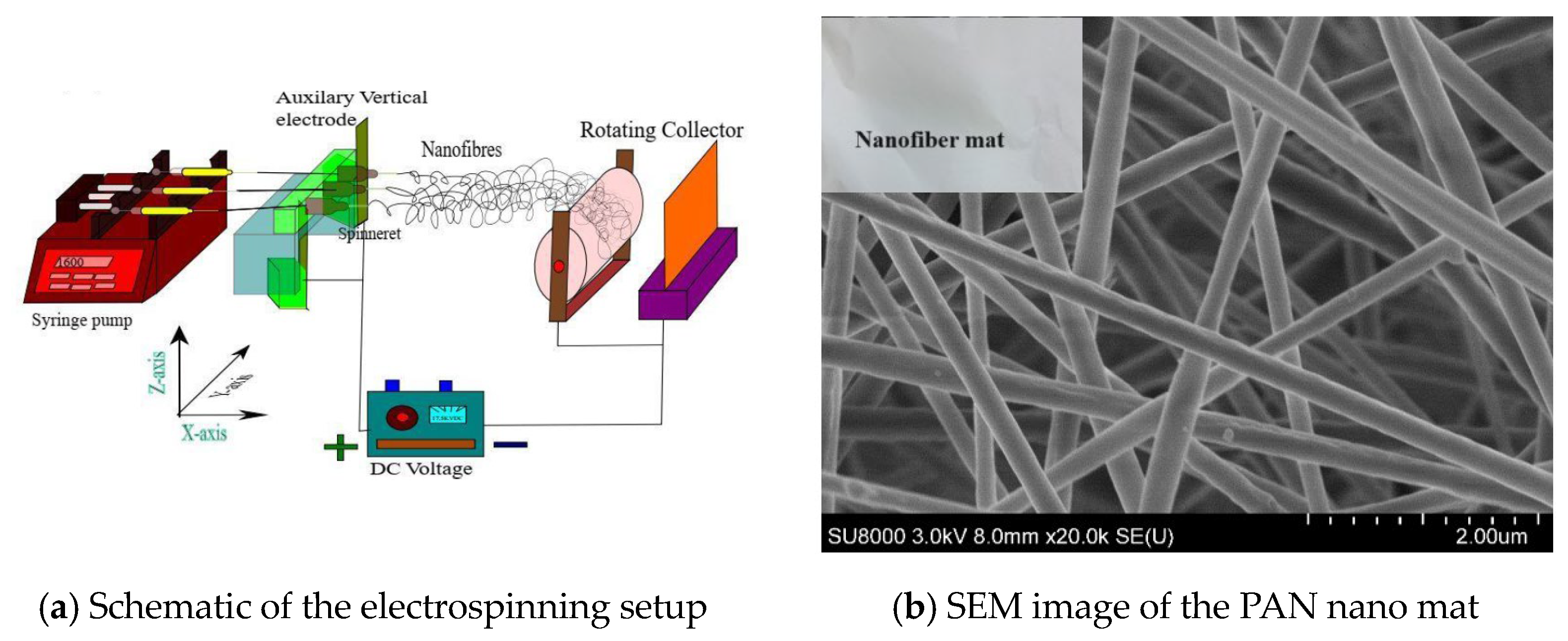
A schematic of an electrospinning setup is shown in Figure 1a, which was designed and developed at the Nano lab, University of Regina. The setup comprises a syringe pump (NE-1600 syringe pump from New Era Pump Systems Inc., New York USA), a voltage power supply (supplied by Gamma High Voltage and Research, Florida, USA, and a rotating drum collector purchased from MTI Corporations, California USA. The electrospun mats were collected on an aluminum foil over the rotating drum. For doping the graphite particles, the graphite was mixed with the PAN/DMF solution and then electrospun to produce the graphite-doped PAN nanofiber mats as shown in Figure 1b. The produced graphite-doped PAN nanofiber mats were then used to produce graphite-doped NPC liners. At first, three different PAN volume fractions of 0.1%, 0.25%, and 0.5% were selected for producing nanofiber mats. Then, three graphite volume fractions of 0.05%, 0.1%, and 0.2% were added to each PAN volume fraction to produce the graphite-doped nanofiber mats. In total, 12 different types of PAN and graphite-doped PAN nanomats were produced for the experiment.
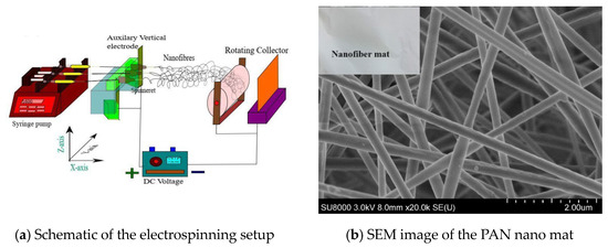
Figure 1.
Electrospinning setup.
2.2. Fabrication of PAN Nanofiber and Graphite-Doped NPC Liners
The PAN NPC and graphite-doped PAN NPC liners were fabricated following ASTM D5229 standards. This standard was used for the polymer composite liners for the absorption analysis. According to the standard, the specimen size of 100 mm × 100 mm square with a thickness of 2 mm was fabricated. The fabrication mold was purchased from Rusty Design Inc., Mississauga, Canada with a specific dimension for our absorption analysis testing. The liners are produced using three layers of PAN and graphite-doped PAN nanofiber mats. The fabrication of NPC liners was started by laminating the bottom layer of a 1 mm thick polymeric matrix, and after that, the PAN nanofiber mats or graphite-doped PAN nanofiber mats were placed. Then, the top layer of the epoxy polymer matrix, with a 1 mm thickness, was laminated.
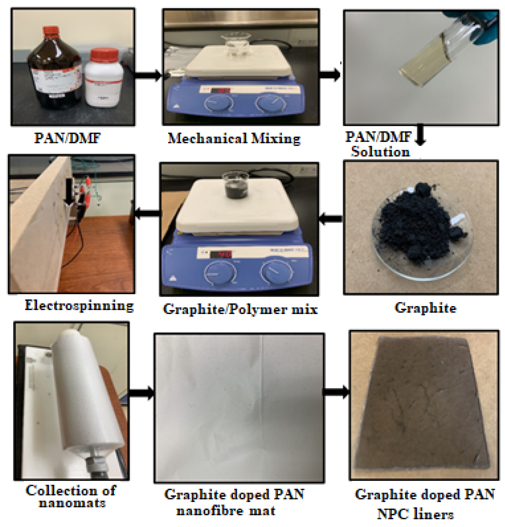
The fabrication of liners started with a clean and dry mold. The matrix was prepared by mixing 27 mL of resin with 10 mL of hardener, which was then stirred gently with a wooden stick until the hardener was completely mixed with the resin without any air bubbles. To make 2 mm thick NPCL specimens, a total of 36 mL of resin was required. First, 18 mL was poured into the mold to produce the bottom layer (1 mm thick), and then the PAN nanofiber mats or graphite-doped PAN nanofiber mats were placed above the bottom layer of the polymer matrix. Then, the remaining 18 mL was poured on top of the nanofiber mat layer. Then, the mold was kept for 24 h to cure under atmospheric conditions and then stored for testing. The sequence of the NPC liners fabrication is shown in Figure 2.
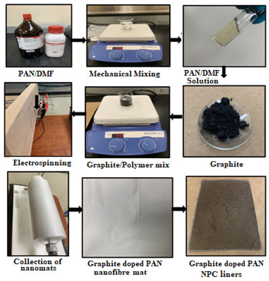
Figure 2.
Fabrication sequence of PAN and graphite-doped PAN NPC liners.
3. Absorption Tests
The ASTM D5229 standard was followed for the absorption analysis of the PAN and graphite-doped PAN NPC liners. This standard measures the rate of absorption by saturation in weight and indicates that the immersed specimens should be measured at regular intervals to check whether the specimens have attained saturation with the medium. The measuring was carried out using a weighing scale with the capability of measuring 0.1 mg. The absorption analysis was carried out under three different conditions: water at room temperature (23 °C), water at 50 °C, and light oil at room temperature. All the specimens were kept in the same position throughout the weight measurement.
Equation (1) was used to find the absorption percentage.
where
- Wa is the weight of the specimen after absorption,
- Wi is the weight of the initial specimen.
If the average absorption percentage of the material changes by less than 0.01% within a particular time, then the effective absorption equilibrium was used and expressed as
where
- 3.
- Wa is the weight at the current measurement,
- 4.
- Wa−1 is the weight at the previous measurement.
- 5.
- Wb is the weight at the baseline measurement.
4. Results and Discussions
4.1. Morphological Characteristics of Graphite-Doped PAN Nanofiber Mats
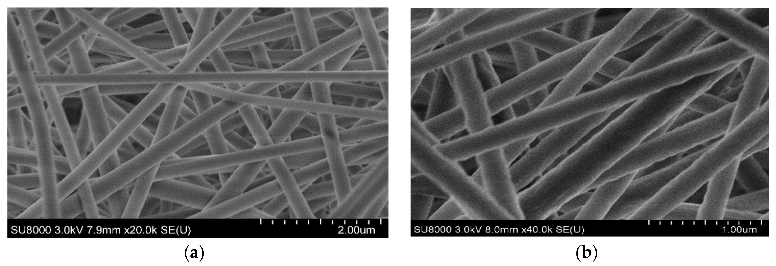
The electrospun PAN nanofibers and graphite-doped PAN nanofiber mats were analyzed using SEM images to understand their surface morphology (ref. Figure 3a,b). The diameter of the graphite-doped nanofibers was increased compared to the PAN nanofibers due to the addition of graphite into the PAN nanofiber. The continuous and uniformly distributed nanofibers produced were denser compared to the PAN nanofibers due to the addition of graphite, which improved the porosity of the NPC liners.

Figure 3.
Electrospun nanofibers mats. (a) 0.5 vol.% PAN nanofiber mat; (b) 0.2 vol.% graphite doped with 0.5 vol. % PAN nanofiber mat.
4.2. Absorption Characterization of Graphite-Doped PAN NPC Liners
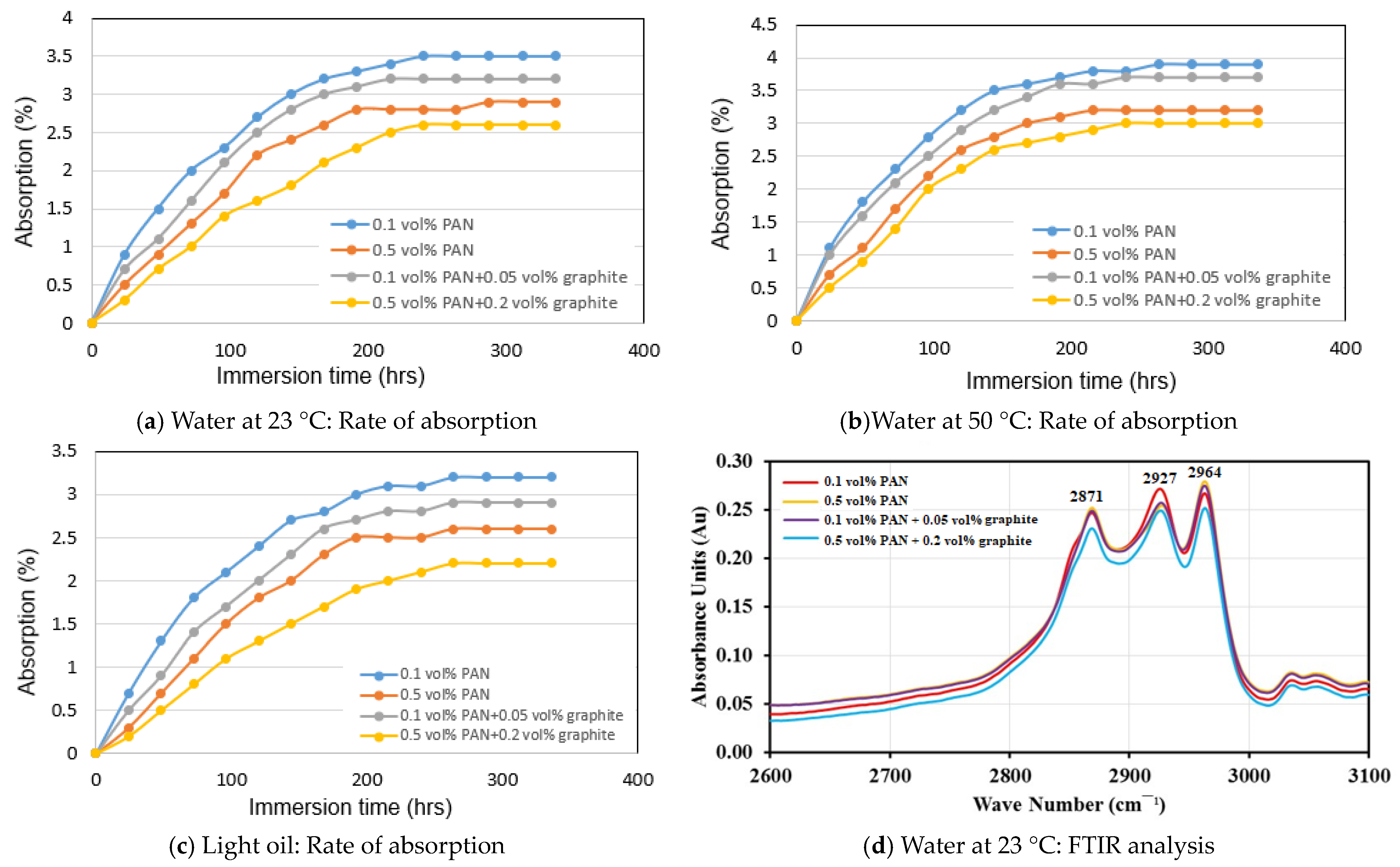
The rate of absorption in water at 23 °C, water at 50 °C, and light oil at room temperature for PAN and graphite-doped PAN NPC liners is shown in Figure 4a–c. The results indicate that the 0.1 vol.% PAN NPC liners showed the highest absorption rate of 3.9% for water at 50 °C, 3.5% for water at 23 °C, and 3.2% for light oil, respectively. However, the lowest absorption rate of 3.2% for water at 50 °C, 2.9% for water at 23 °C, and 2.6% for light oil was observed for the 0.5 vol.% PAN NPC liners. The reduction in absorption rate is due to the increased addition of PAN nanofibers in the NPC liners, which might have reduced the free volume within the NPC liners.
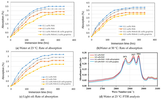
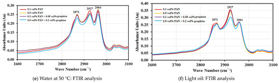
Figure 4.
Rate of absorption and FTIR absorption analysis of NPC and graphite-doped NPC liners.
A similar observation can be seen with the addition of graphite-doped PAN NPC liners. The addition of 0.05 vol.% of graphite doped with 0.1 vol.% PAN-infused NPC liners resulted in an absorption rate of 3.7% for water at 50 °C. However, following the addition of 0.2 vol.% of graphite doped with 0.5 vol.% PAN NPC liners, the absorption rate was reduced to 3% for the same medium. For the 0.05 vol.% of graphite doped with 0.1 vol.% PAN NPC liners, the absorption rates were 3.2% for water at 23 °C and 2.9% for light oil, respectively. Similarly, the addition of 0.2 vol.% of graphite-doped with 0.5 vol.% PAN NPC liners resulted in absorption rates of 2.6% for water at 23 °C and 2.2% for light oil, respectively.
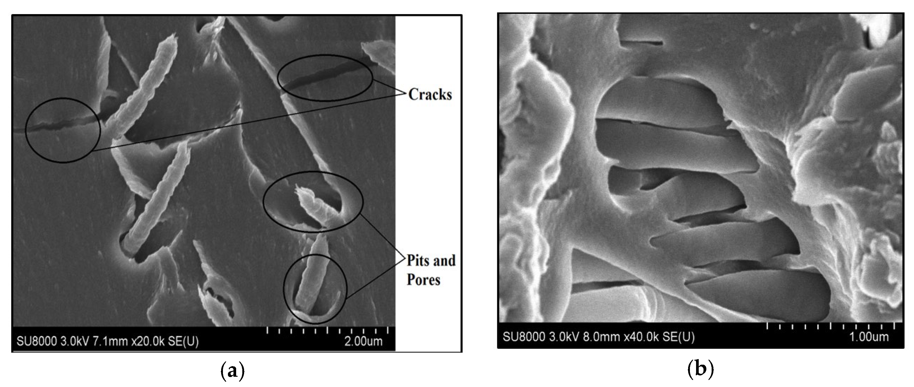
The change in absorption behavior could be attributed to the addition of graphite with PAN nanofibers, as can be seen in the SEM image of 0.2 vol.% graphite doped with 0.5 vol.% PAN NPC liners (ref. Figure 5b). The densely packed graphite-doped nanofibers could have strongly packed the interlaminar region and also reduced porous structures. This higher-order packing with graphite-doped continuous PAN nanofibers has resulted in filling the pores and comparatively reduced the absorption rate.
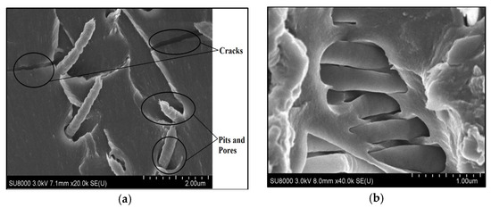
Figure 5.
SEM images of PAN nanofiber and graphite-doped PAN NPCL liners. (a) 0.5 vol.% of PAN NPC liners; (b) 0.5 vol.% PAN doped with 0.2 vol.% graphite NPC liners.
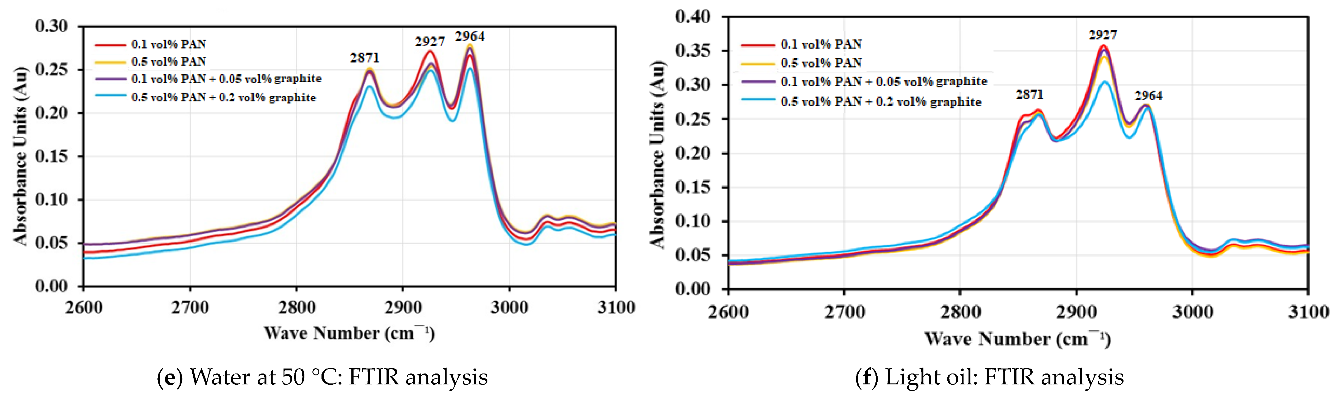
Figure 4d–f show the attenuated total reflectance (ATR) FTIR analysis of PAN and graphite-doped PAN NPC liners immersed in water at 23 °C, water at 50 °C, and light oil for 336 h, respectively. The infrared frequencies and the absorbance bands are shown in the figure. The frequencies from 3320 cm−1 to 3430 cm−1 are related to O-H group stretching, and frequencies from 2800 cm−1 to 3000 cm−1 are related to the aliphatic C-H stretching vibrations. Further, the frequencies between 2800 cm−1 and 3000 cm−1 are the absorbance peaks and were observed for PAN and graphite-doped PAN NPC liners for water at 23 °C, water at 50 °C, and light oil at room temperature, respectively.
Figure 4d shows the absorption peak of specimens immersed in water at 23 °C for 336 h. The C-H stretching at 2927 cm−1 varies for different volume fractions of PAN and graphite-doped NPC liners. The 0.1 vol.% PAN NPC liners have the highest peak at 0.2678 absorbance units for the C-H stretching followed by 0.5 vol.% PAN NPC liners with an absorbance peak of 0.2540 Au. Similarly, the doping of 0.05 vol.% graphite with 0.1 vol.% PAN has shown the C-H stretching peak at 0.2576 Au, and the 0.2 vol.% graphite doped with 0.5 vol.% PAN has the lowest absorption peak of 0.2488 Au.
Figure 4e shows the absorption peak of specimens immersed in water at 50 °C after 336 h of immersion. The 0.1 vol.% PAN NPC liners have the highest peak of 0.2705 absorbance units at the C-H stretching, followed by 0.05 vol.% graphite doped with 0.1 vol.% PAN with 0.2650 absorbance units, respectively. The absorption peak of 0.5 vol.% PAN NPC lines was 0.2594 absorbance units and the 0.2 vol.% graphite doped with 0.5 vol.% PAN NPC liners with 0.2547 absorbance units, respectively.
Similar behavior could be seen for the specimens immersed in light oil for 336 h (Figure 4f). The 0.1 vol.% PAN NPC liners have the highest peak of 0.3509 absorbance units at the C-H stretching, followed by 0.3500 absorbance units for 0.05 vol.% graphite doped with 0.1 vol.% PAN. The absorbance peak for 0.5 vol.% PAN NPC liners was at 0.3389 Au and the 0.2 vol.% graphite doped with 0.5 vol.% PAN NPC liners was at 0.3032 absorbance units.
By comparing the frequencies for all the mediums, the light oil has shown slightly higher frequency peaks at 2927 cm−1 when compared to the specimens immersed in water at 23 °C and water at 50 °C, respectively. This might be due to the combination of the C-H functional group from the epoxy polymer and the absorbed light oil. As the light oil was observed in the liners, it increased the level of C-H functional groups, which resulted in higher frequencies for light oil compared to water at 23 °C and water at 50 °C, respectively. This confirms that the light oil permeates through the epoxy polymer and the infused nanofibers mats prevent the light oil from diffusing further into liners. Figure 5 shows SEM images of the infused nanofiber mats within the NPC liners, which have prevented the light oil from diffusing beyond the nanofiber mats. Similar observations could be seen for all water at 23 °C and 50 °C. Moreover, the highest absorbance peak was for 0.1 vol.% PAN NPC liners, and the lowest absorption peak was observed for 0.2 vol.% graphite-doped 0.5 vol.% PAN NPC liners. The 0.5 vol.% PAN and 0.05 vol.% graphite-doped 0.1 vol.% PAN NPC liners have slightly better absorbance peaks when compared to the 0.1 vol.% PAN liners. This clearly shows that the higher volume fraction of PAN mats and the doping of graphite into PAN NPC liners have improved the specimen against absorption and decreased the penetration of mediums into the specimen. From the results, it can be concluded that the higher volume fraction of PAN and the doping of graphite with PAN filled the pits and pores of the composite specimen. Further, the reinforcements did not allow the composite specimen to form voids and also strongly bonded with the matrix, controlling the further diffusion of the mediums.
5. Conclusions
An electrospinning setup was designed and developed for fabricating PAN and graphite-doped PAN nanofiber mats and was used to manufacture the Nanofiber Polymer Composite (NPC) liners. The liners were tested with three mediums to characterize their absorption behavior. Increasing the volume fractions of PAN and graphite-doped PAN nanofiber mats into the NPC liners has comparatively decreased the absorption percentage and improved the absorption characteristics of the NPC liners. The doping of 0.05 vol.% PAN and 0.2 vol.% graphite doped with 0.1 vol.% and 0.5 vol.% PAN have reduced the absorption percentage by 0.3% for both heavy oil and water at 23 °C and by 0.2% for the water at 50 °C, respectively. The results are from the lab scale tests and further research is required to extend the research to the field scale, which is the main limitation of this research.
Author Contributions
Conceptualization, N.B. and J.M.; methodology, N.B. and J.M.; formal analysis, D.A., N.B. and J.M.; writing—original draft preparation, D.A. and J.M.; writing—review and editing, J.M.; supervision, J.M. All authors have read and agreed to the published version of the manuscript.
Funding
This research was partially supported by the Natural Sciences and Engineering Research Council of Canada (NSERC DDG-2020-00046).
Institutional Review Board Statement
Not applicable.
Informed Consent Statement
Not applicable.
Data Availability Statement
Data are included as results in the manuscript.
Conflicts of Interest
The authors declare no conflicts of interest.
References
- Tan, Z.; Liuyang, Y.; Dalei, D.; Zhenbo, W.; Frank, C.; Mingyang, Z.; Youhai, J. Development mechanism of internal local corrosion of X80 pipeline steel. J. Mater. Sci. Technol. 2020, 49, 186–201. [Google Scholar] [CrossRef]
- Barton, N.A.; Farewell, T.S.; Hallett, S.H.; Acland, T.F. Improving pipe failure predictions: Factors affecting pipe failure in drinking water networks. Water Res. 2019, 164, 114926–114942. [Google Scholar] [CrossRef] [PubMed]
- Suriani, M.J.; Nik, W.B. Hybrid-biocomposite material for corrosion prevention in pipeline: A review. Corros. Sci. Technol. 2017, 16, 85–89. [Google Scholar]
- Bharatiya, U.; Gal, P.; Agrawal, A.; Shah, M.; Sircar, A. Effect of corrosion on crude oil & natural gas pipeline with emphasis on prevention by ecofriendly corrosion inhibitors: A comprehensive review. J. Bio- Tribo-Corros. 2019, 5, 35. [Google Scholar]
- Fadil, F.; Affandi, N.D.; Misnon, M.I.; Bonnia, N.N.; Harun, A.M.; Alam, M.K. Review on electrospun nanofiber-applied products. Polymers 2021, 13, 2087. [Google Scholar] [CrossRef] [PubMed]
- Haleem, A.; Shafiq, A.; Chen, S.-Q.; Nazar, M. A Comprehensive Review on Adsorption, Photocatalytic and Chemical Degradation of Dyes and Nitro-Compounds over Different Kinds of Porous and Composite Materials. Molecules 2023, 28, 1081. [Google Scholar] [CrossRef] [PubMed]
- Aboudi, J.; Arnold, S.; Bednarcyk, B. Micromechanics of Composite Materials; Butterworth-Heinemann: Oxford, UK, 2013; 984p. [Google Scholar]
- Masuelli, M.A. Introduction of fibre-reinforced polymers-polymers and composites: Concepts, properties and processes. In Fiber Reinforced Polymers-the Technology Applied for Concrete Repair; IntechOpen: London, UK, 2013; pp. 3–40. [Google Scholar]
- Fan, Z.; Santare, M.H.; Advani, S.G. Interlaminar shear strength of glass fibre reinforced epoxy composites enhanced with multi-walled carbon nanotubes. Compos. Part A Appl. Sci. Manuf. 2008, 39, 540–554. [Google Scholar] [CrossRef]
- Chen, Q.; Zhang, L.; Rahman, A.; Zhou, Z.; Wu, X.F.; Fong, H. Hybrid multi-scale epoxy composite made of conventional carbon fibre fabrics with interlaminar regions containing electrospun carbon nanofiber mats. Compos. Part A Appl. Sci. Manuf. 2011, 42, 2036–2042. [Google Scholar]
- Peng, K.; Wan, Y.J.; Ren, D.Y.; Zeng, Q.W.; Tang, L.C. Scalable preparation of multiscale carbon nanotube/glass fiber reinforcements and their application in polymer composites. Fibers Polym. 2014, 15, 1242–1250. [Google Scholar] [CrossRef]
- Srivatsan, T.S. A Review of Hybrid Materials: Synthesis, Characterization, and Application G. Kickelbick (Ed.). Mater. Manuf. Process 2009, 24, 1231. [Google Scholar] [CrossRef]
- Rivero, P.J.; Redin, D.M.; Rodríguez, R.J. Electrospinning: A Powerful Tool to Improve the Corrosion Resistance of Metallic Surfaces Using Nanofibrous Coatings. Metals 2020, 10, 350. [Google Scholar] [CrossRef]
- Condé-Wolter, J.; Ruf, M.G.; Liebsch, A.; Lebelt, T.; Koch, I.; Drechsler, K.; Gude, M. Hydrogen permeability of thermoplastic composites and liner systems for future mobility applications. Compos. Part A Appl. Sci. Manuf. 2023, 167, 107446–107459. [Google Scholar] [CrossRef]
- Balan, N.V.M. Graphite Doped PAN Nanofiber Mats Infused Polymer Composite Pipeliners: Experimental Diffusion Characterization. Master’s Thesis, University of Regina, Regina, SK, Canada, 2022. [Google Scholar]
Disclaimer/Publisher’s Note: The statements, opinions and data contained in all publications are solely those of the individual author(s) and contributor(s) and not of MDPI and/or the editor(s). MDPI and/or the editor(s) disclaim responsibility for any injury to people or property resulting from any ideas, methods, instructions or products referred to in the content. |
© 2024 by the authors. Licensee MDPI, Basel, Switzerland. This article is an open access article distributed under the terms and conditions of the Creative Commons Attribution (CC BY) license (https://creativecommons.org/licenses/by/4.0/).