Proceeding Paper

Experimental Investigation on Abrasive Flow Finishing of FDM-Printed Polymeric Y-Shaped Nozzle †

1
School of Engineering, University of Lincoln, Brayford Pool, Lincoln LN6 7TS, UK
2
Centre for Research Impact & Outcome, Chitkara University Institute of Engineering and Technology, Chitkara University, Rajpura 140401, Punjab, India
3
School of Mechanical Engineering, Shandong University of Technology, Zibo 255000, China
4
University Centre for Research and Development, Chandigarh University, Mohali 140413, Punjab, India
5
Clean Energy Technologies Research Institute (CETRI), Process Systems Engineering, Faculty of Engineering and Applied Science, University of Regina, 3737 Wascana Parkway, Regina, SK S4S 0A2, Canada
*
Authors to whom correspondence should be addressed.
Presented at the 1st International Conference on Industrial, Manufacturing, and Process Engineering (ICIMP-2024), Regina, Canada, 27–29 June 2024.
Eng. Proc. 2024, 76(1), 107; https://doi.org/10.3390/engproc2024076107
Published: 25 April 2025

Abstract

An experiment examined the impact of 0.2% to 1.0% w/w graphite nanoparticles in 15W40 lubricating oil on tribological and rheological behavior. The analysis, conducted with a Pin on Disc machine and Four-Ball tester, revealed improved tribological properties and a 30% reduction in the friction coefficient compared to fresh 15W40. Wear was negligible, and extreme pressure performance increased by approximately 20%. SEM morphology confirmed the presence of graphite nanoparticles on the tribopair surface, indicating enhanced lubricant performance.

1. Introduction

The integration of Fused Deposition Modeling (FDM) into the manufacturing sector has significantly revolutionized the production of complex geometrical designs, enabling rapid prototyping and customization with unprecedented flexibility [1]. This additive manufacturing technique has made it possible to construct objects layer by layer from digital models, facilitating the creation of prototypes and final products with intricate shapes that were previously challenging or impossible to achieve through conventional methods [2]. However, the inherent nature of FDM, building objects layer by layer, often results in a finished product with a surface roughness that does not meet the required standards for many applications. The quest for improved surface quality in FDM-printed components has led researchers to explore various post-processing techniques, among which abrasive flow machining (AFM) has shown considerable promise [3].
Fused Deposition Modeling’s principle advantage lies in its ability to simplify and expedite the design-to-product process, offering substantial reductions in time and cost compared to traditional manufacturing methods. Despite these benefits, the technique’s Achilles’ heel remains the surface finish of the printed objects [4]. The layered construction intrinsic to FDM creates a stair-stepping effect, especially on curved surfaces, leading to a texture that can be esthetically displeasing and functionally inadequate [5]. The literature is replete with studies attempting to mitigate these effects through mechanical, chemical, and thermal post-processing methods [6,7,8,9,10,11,12]. Among these, abrasive flow machining stands out for its ability to uniformly smooth surfaces and refine complex internal geometries without the need for direct access. The process involves forcing a semi-solid abrasive medium under pressure through or across the part’s surface [13,14,15,16,17,18,19]. This unique capability makes AFM particularly suitable for improving the surface quality of FDM-printed parts, where traditional finishing methods may fall short [20,21,22]. Prior research has focused on optimizing the AFM process, examining variables such as abrasive particle size, concentration, and the viscosity of the medium, yet a comprehensive study specifically tailored to the nuances of FDM-printed polymeric Y-shaped nozzles remains a niche yet critical area of exploration.

2. Materials and Method

This study utilized Acrylonitrile Butadiene Styrene (ABS) material for both the fabrication of the Y-shaped nozzles and the fixtures used in the finishing process. ABS was chosen due to its excellent mechanical properties, making it ideal for both the manufacturing and experimental phases. The design and fabrication of the Y-shaped nozzle and its corresponding fixture were carried out using Autodesk Fusion 360 (Version 2.0.18220), a comprehensive tool for CAD, CAM, and CAE. The precise dimensions and configurations of the nozzle and fixture were meticulously planned to ensure consistency and reliability in the abrasive flow machining (AFM) process. Figure 1 and Figure 2 illustrate the design of the Y-shaped nozzle and its fixture, respectively, showcasing the attention to detail and the specifications tailored for optimal AFM performance.

3. Experimental Setup and Procedure

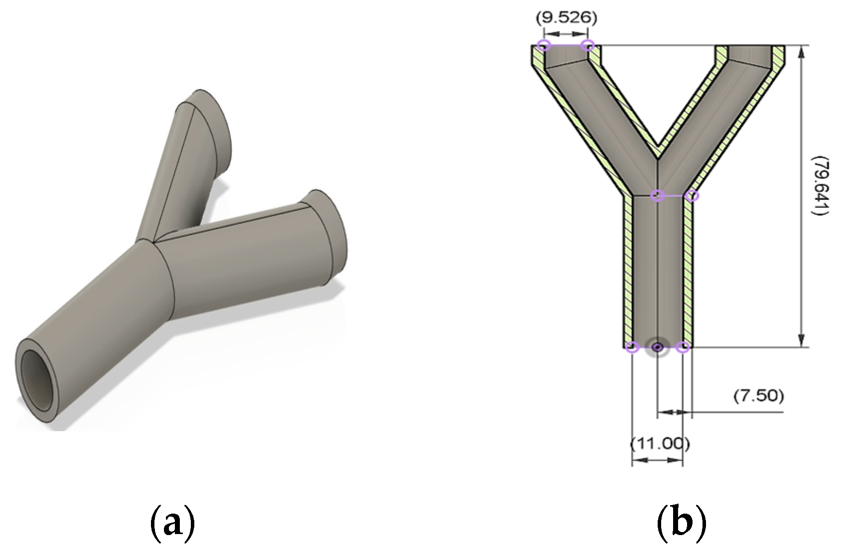
3.1. Printing of Y-Shaped Nozzles

The Y-shaped nozzles were produced using an FDM 3D printer with Acrylonitrile Butadiene Styrene (ABS) as the print material. The printing parameters were calibrated to ensure dimensional accuracy and repeatability. The layer height was set to optimize the balance between print speed and surface finish quality. After printing, the nozzles underwent an initial inspection to ensure they met the pre-defined criteria for the experimental trials.

3.2. Fabrication of AFM Fixtures

The fixtures for securing the nozzles during the AFM process were also printed with ABS material to maintain consistency in thermal expansion properties. These fixtures were designed to hold the nozzles firmly in place, providing a secure pathway for the abrasive medium to flow through without causing deformation to the printed parts.
Figure 3 showcases the FDM-printed Y-shaped nozzle alongside its custom-designed AFM fixture. This configuration highlights the precision in design and manufacturing, illustrating how the nozzle and fixture are tailored to facilitate the abrasive flow finishing process effectively.

3.3. Preparation of AFM Medium

The AFM medium was carefully formulated using waste rubber as the polymer base, EDM oil as the liquid synthesizer, glycerin for its properties as an additive, and Silicon Carbide (SiC) particles for abrasion. This combination was chosen for its effective balance between viscosity, lubricity, and abrasive capabilities, essential for achieving a high-quality surface finish on the FDM-printed Y-shaped nozzles. The setup for the abrasive flow machining process involved specialized machinery designed to circulate the AFM medium through the nozzles under controlled flow conditions. The nozzles, secured within their custom-designed fixtures, were positioned to ensure uniform exposure to the abrasive medium, optimizing the finishing process.
Figure 4 illustrates the nine samples of the AFM medium, each meticulously prepared with distinct ratios of waste rubber, EDM oil, glycerin, and SiC particles. These samples are integral to the experimental investigation aimed at optimizing the surface finish of FDM-printed Y-shaped nozzles through abrasive flow machining.

3.4. Abrasive Flow Machining Process

The AFM machine was set up with the prepared medium. The nozzles, secured in their fixtures, were attached to the machine’s inlet and outlet ports to ensure a seamless flow of the abrasive medium through the internal channels. The flow rate and pressure were meticulously controlled to match the pre-determined parameters. The flow conditions were selected to optimize the media’s ability to abrade the surfaces without causing any structural damage to the nozzles.

3.5. Parameter Optimization

A systematic approach was adopted to optimize the AFM parameters. The variables under consideration included the volume of the abrasive medium, the pressure at which it was delivered, the flow rate, and the number of cycles the medium was passed through the nozzle. The process parameters were adjusted incrementally, and their effects on the surface finish were evaluated after each trial. The use of a Taguchi design in the experiments facilitated the efficient analysis of the data and the identification of optimal settings.

3.6. Surface Roughness Measurement

The surface roughness of the nozzles was measured before and after the abrasive flow machining using a contact profilometer. The measurements were taken at multiple points along the internal surface to ensure a comprehensive assessment of the finishing process’ effectiveness. The data obtained were statistically analyzed to understand the relationship between the AFM parameters and the resulting surface quality.

3.7. Experimental Trials

Multiple experimental trials were conducted according to the design of experiments. Each trial was carefully documented, with all parameters and resulting surface roughness measurements recorded. The trials were repeated to ensure the reliability of the results and to identify any potential variability in the outcomes.

4. Results and Analysis

4.1. Surface Roughness Outcomes

The primary focus of the analysis was the surface roughness of the FDM-printed Y-shaped nozzles post-AFM treatment. The data revealed a substantial improvement in surface quality. The roughness measurements taken pre- and post-process indicated a marked reduction, with the best-performing sample exhibiting a decrease in roughness from an initial average of 12.5 µm down to a refined 1.2 µm, representing an improvement of over 90%. Table 1 and Table 2 display four process parameters that were used as control factors in the experimentation: abrasive particle concentration, layer thickness, finishing time, and abrasive particle mesh size. Low, medium, and high levels are assigned to each parameter. These process settings and their values were chosen based on the existing literature on AFM.
Table 2 shows the response parameter, which is the percent improvement in surface quality, i.e., the reduction in Ra.
The main effects plot for S/N ratios indicates that the optimal viscosity setting for the AFM process is at 40, where the mean S/N ratio is at its peak, suggesting the highest quality output. The layer thickness of 0.2 mm is identified as the ideal value, as it corresponds to the highest mean S/N ratio, denoting superior surface finish. For finishing time, 45 min is the optimal duration, as it maximizes the mean S/N ratio, beyond which no quality improvement is observed, as shown in Figure 5.

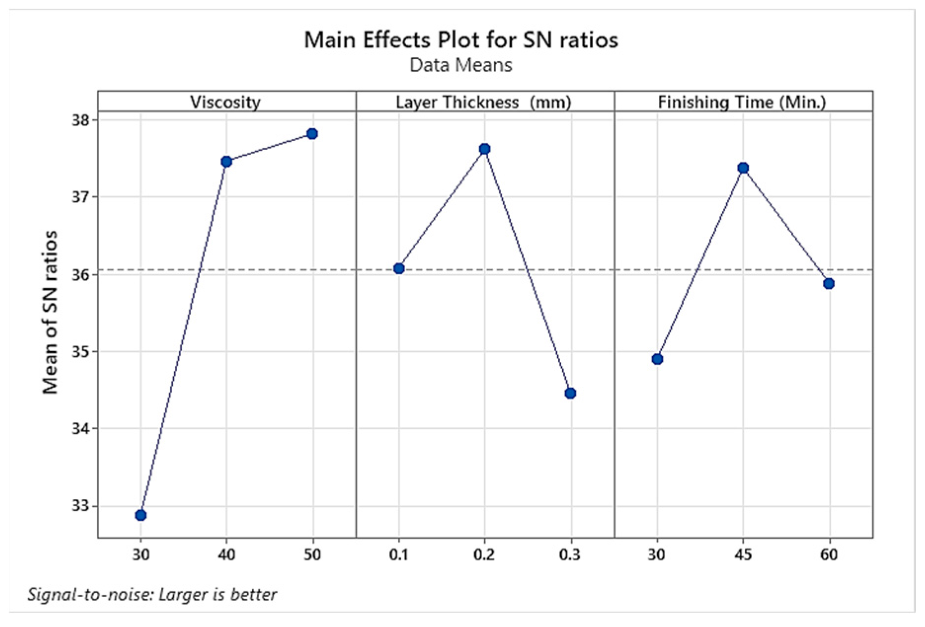
4.2. Influence of AFM Parameters

The Taguchi method for the design of experiments provided a clear insight into the influence of each AFM parameter on the surface finish. It was observed that the abrasive concentration and mesh size had the most significant impact. Higher concentrations of SiC particles and finer mesh sizes contributed to a smoother surface, likely due to the increased number of abrasive contacts with the nozzle’s surface.

4.3. Viscosity’s Role in AFM Efficiency

The viscosity of the AFM medium, adjusted through the incorporation of glycerin, played a crucial role in determining the quality of the finish. Media with higher viscosity were more effective in delivering the abrasive particles uniformly across the surface, leading to a consistent and homogeneous surface finish.

4.4. Statistical Analysis of Results

A statistical analysis of the results, including ANOVA, confirmed the significance of the selected parameters. The analysis highlighted the optimal levels of each parameter for the best surface finish while also providing insights into the interaction between different variables. This statistical approach allowed for a more comprehensive understanding of the AFM process and its effect on the FDM-printed nozzles.

4.5. Comparison with Control Samples

Control samples, which underwent no post-processing, were compared to the treated samples. The contrast was stark, as the untreated nozzles displayed the characteristic layer lines and rough texture typical of FDM prints, while the treated nozzles had a significantly smoother and more uniform surface.

4.6. Process Reproducibility

To ensure the reproducibility of the process, multiple sets of experiments were conducted under the same optimal conditions. The outcomes consistently showed similar improvements in surface roughness, underscoring the reliability of the optimized AFM process parameters.

4.7. Optical Image Analysis

The comparative surface analysis of the FDM-printed Y-shaped nozzle pre- and post-abrasive flow finishing is shown in Figure 6. The top image displays the initial surface with noticeable layer striations characteristic of the FDM process, while the bottom image reveals the substantially smoother surface following the ninth trial of abrasive flow finishing, which corresponds to a media viscosity of 50, a layer thickness of 0.2 mm, a finishing time of 30 min, and the highest surface roughness improvement of 97%.

5. Conclusions

This experimental research on the abrasive flow finishing of FDM-printed polymeric Y-shaped nozzles has culminated in several noteworthy conclusions:
  • AFM significantly improves the surface roughness of FDM-printed ABS Y-shaped nozzles.
  • Optimal AFM parameters were identified for achieving the best surface finish.
  • The study’s optimized AFM process is applicable across various manufacturing sectors.
  • The utilization of waste rubber in AFM media aligns with sustainable manufacturing practices.
  • Future research should explore AFM’s effects on different materials and process automation.
  • AFM-treated FDM parts exhibit a potential increase in viable applications for 3D-printing technologies.

Author Contributions

Conceptualization, methodology, data curation, writing—original draft preparation: A.W.H., S.A., and F.I.; writing—review and editing, formal analysis, funding acquisition: M.Y. and H.I. All authors have read and agreed to the published version of the manuscript.

Funding

This research received no external funding.

Institutional Review Board Statement

Not applicable.

Informed Consent Statement

Not applicable.

Data Availability Statement

Data are contained within the article.

Acknowledgments

The authors would like to express their sincere gratitude to the Clean Energy Technologies Research Institute (CETRI), University of Regina, Canada, for providing the resources to carry out this study.

Conflicts of Interest

The authors declare no conflicts of interest.

References

  1. Gibson, I.; Rosen, D.; Stucker, B.; Khorasani, M. Additive Manufacturing Technologies, 3rd ed.; Springer: Berlin/Heidelberg, Germany, 2021; ISBN 9783030561260. [Google Scholar]
  2. Jyothish Kumar, L.; Pandey, P.M.; Wimpenny, D.I. 3D Printing and Additive Manufacturing Technologies; Springer: Singapore, 2018; ISBN 9789811303050. [Google Scholar]
  3. Dave, H.K.; Davim, J.P. Fused Deposition Modeling Based 3D Printing; Springer: Berlin/Heidelberg, Germany, 2021; ISBN 978-3-030-68024-4. [Google Scholar]
  4. Kumbhar, N.N.; Mulay, A.V. Post Processing Methods Used to Improve Surface Finish of Products Which Are Manufactured by Additive Manufacturing Technologies: A Review. J. Inst. Eng. (India) Ser. C 2018, 99, 481–487. [Google Scholar] [CrossRef]
  5. Pandey, P.M.; Reddy, N.V.; Dhande, S.G. Improvement of Surface Finish by Staircase Machining in Fused Deposition Modeling. J. Mater. Process. Technol. 2003, 132, 323–331. [Google Scholar] [CrossRef]
  6. Hashmi, A.W.; Meena, A.; National, M. Improving the Surface Characteristics of Additively Manufactured Parts: A Review. Mater. Today Proc. 2023, 81, 723–738. [Google Scholar] [CrossRef]
  7. Hashmi, A.W.; Mali, H.S.; Meena, A. A Comprehensive Review on Surface Quality Improvement Methods for Additively Manufactured Parts. Rapid Prototyp. J. 2023, 29, 504–557. [Google Scholar] [CrossRef]
  8. Hashmi, A.W.; Mali, H.S.; Meena, A. Surface quality improvement methods of additively manufactured parts: A review. Solid State Technol.. 2020, 63, 23477–23517. [Google Scholar] [CrossRef]
  9. Hashmi, A.W.; Mali, H.S.; Meena, A.; Ahmad, S.; Puerta, A.P.V.; Kunkel, M.E. A critical review of mechanical-based post-processing techniques for additively manufactured parts. In Post-Processing Techniques for Additive Manufacturing; Alam, Z., Iqbal, F., Khan, D.A., Eds.; CRC Press: Boca Raton, FL, USA, 2024; pp. 99–127. [Google Scholar] [CrossRef]
  10. Hashmi, A.W.; Mali, H.S.; Meena, A. The Surface Quality Improvement Methods for FDM Printed Parts: A Review. In Fused Deposition Modeling Based 3D Printing; Dave, H.K., Davim, J.P., Eds.; Springer International Publishing: Cham, Switzerland, 2021; pp. 167–194. ISBN 978-3-030-68024-4. [Google Scholar]
  11. Hashmi, A.W.; Mali, H.S.; Meena, A.; Puerta, V.; Kunkel, M.E. Surface Characteristics Improvement Methods for Metal Additively Manufactured Parts: A Review. Adv. Mater. Process. Technol. 2022, 8, 4524–4563. [Google Scholar] [CrossRef]
  12. Hashmi, A.W.; Mali, H.S.; Meena, A.; Saxena, K.K.; Ahmad, S.; Agrawal, M.K.; Sagbas, B.; Puerta, A.P.V.; Khan, M.I. A Comprehensive Review on Surface Post-Treatments for Freeform Surfaces of Bio-Implants. J. Mater. Res. Technol. 2023, 23, 4866–4908. [Google Scholar] [CrossRef]
  13. Hashmi, A.W.; Mali, H.S.; Meena, A.; Saxena, K.K.; Puerta, A.P.V.; Rao, U.S.; Buddhi, D.; Mohammed, K.A. Design and Modeling of Abrasive Flow Finishing of Freeform Surfaces of FDM Printed Femoral Component of Knee Implant Pattern. Int. J. Interact. Des. Manuf. (IJIDeM) 2022, 17, 2507–2526. [Google Scholar] [CrossRef]
  14. Hashmi, A.W.; Mali, H.S.; Meena, A.; Saxena, K.K.; Puerta, A.P.V.; Buddhi, D. A Newly Developed Coal-Ash-Based AFM Media Characterization for Abrasive Flow Finishing of FDM Printed Hemispherical Ball Shape. Int. J. Interact. Des. Manuf. (IJIDeM) 2022, 17, 2283–2298. [Google Scholar] [CrossRef]
  15. Hashmi, A.W.; Mali, H.S.; Meena, A.; Ahmad, S.; Tian, Y. A Novel Eco-Friendly Abrasive Media Based Abrasive Flow Machining of 3D Printed PLA Parts Using IGWO and ANN. Rapid Prototyp. J. 2023, 29, 2019–2038. [Google Scholar] [CrossRef]
  16. Mali, H.S.; Hashmi, A.W.; Jangid, M.K.; Meena, A. Experimental Investigation on AFF of FDM Printed Pattern for Extrusion Die Insert. In Advances in Micro and Nano Manufacturing and Surface Engineering; Springer: Berlin/Heidelberg, Germany, 2023; pp. 199–211. [Google Scholar]
  17. Wahab Hashmi, A.; Singh Mali, H.; Meena, A. Experimental Investigation on Abrasive Flow Machining (AFM) of FDM Printed Hollow Truncated Cone Parts. Mater. Today Proc. 2022, 56, 1369–1375. [Google Scholar] [CrossRef]
  18. Hashmi, A.W.; Mali, H.S.; Meena, A. An Experimental Investigation of Viscosity of a Newly Developed Natural Polymer-Based Media for Abrasive Flow Machining (AFM) of 3D Printed ABS Parts. J. Eng. Res. 2021, 1–18. [Google Scholar] [CrossRef]
  19. Wahab Hashmi, A.; Singh Mali, H.; Meena, A. Design and Fabrication of a Low-Cost One-Way Abrasive Flow Finishing Set-up Using 3D Printed Parts. Mater. Today Proc. 2022, 62, 7554–7563. [Google Scholar] [CrossRef]
  20. Chohan, J.S.; Singh, R. Pre and Post Processing Techniques to Improve Surface Characteristics of FDM Parts: A State of Art Review and Future Applications. Rapid Prototyp. J. 2017, 23, 495–513. [Google Scholar] [CrossRef]
  21. Boparai, K.S.; Singh, R.; Singh, H. Development of Rapid Tooling Using Fused Deposition Modeling: A Review. Rapid Prototyp. J. 2016, 22, 281–299. [Google Scholar] [CrossRef]
  22. Singh, D.; Singh, R.; Boparai, K.S. Development and Surface Improvement of FDM Pattern Based Investment Casting of Biomedical Implants: A State of Art Review. J. Manuf. Process. 2018, 31, 80–95. [Google Scholar] [CrossRef]
Figure 1. Design of the Y-shaped nozzle: (a) 3D model of Y-shaped nozzle; (b) cross-sectional view of Y-shaped nozzle.
Engproc 76 00107 g001
Figure 2. AFM fixture for Y-shaped nozzle: (a) top view; (b) bottom view; (c) cross-sectional view of AFM fixture assembly.
Engproc 76 00107 g002
Figure 3. FDM-printed AFM fixture for Y-shaped nozzle.
Engproc 76 00107 g003
Figure 4. Nine samples of the AFM medium.
Engproc 76 00107 g004
Figure 5. Optimization of AFM process parameters for FDM-printed nozzles: a main effects plot for S/N ratios.
Engproc 76 00107 g005
Figure 6. Surface texture comparison of FDM-printed Y-shaped nozzle: (a) before abrasive flow finishing and (b) after optimal abrasive flow finishing.
Engproc 76 00107 g006
Table 1. Experimental design of the AFM process parameters and their respective levels (finishing of FDM-printed “Y-shaped nozzle”).
ParametersLevel 1Level 2Level 3
Abrasive mesh size120220320
%Abrasive concentration335067
Layer thickness0.10.20.3
Finishing time (min)304560
Table 2. Design for a surface enhancement experiment on an FDM-based 3D-printed “die insert” pattern.
S. N.ViscosityLayer Thickness (mm)Finishing Time (Min.)Initial Surface Roughness
(Ra in µm)
Post-Finishing Surface Roughness
(Ra in µm)
% Improvement in (ΔRa)
1300.13013.8009.1633.62
2400.24523.1302.2090.49
3600.36028.6012.8355.14
4300.26022.9011.4350.09
5400.33029.0313.7352.70
6500.14516.9002.0387.99
7300.34530.0014.7650.80
8400.16014.0001.7687.43
9500.23023.3300.7097.00
Disclaimer/Publisher’s Note: The statements, opinions and data contained in all publications are solely those of the individual author(s) and contributor(s) and not of MDPI and/or the editor(s). MDPI and/or the editor(s) disclaim responsibility for any injury to people or property resulting from any ideas, methods, instructions or products referred to in the content.

