Abstract
Shape-memory alloys have various applications in different fields including medicine, robotics, aeronautics, and micro-electromechanical systems. This paper discusses shrink-fit joints formed by shape-memory alloy elements and their application for the axial fixation of mechanical components. The use of shape-memory alloys gives the shrink-fits some specific features: ease of assembly, insensitivity to tooling and human error, chemical resistance, low cost, etc. The friction force created between the components is experimentally investigated as a function of two parameters—the substrate diameter and the surface roughness (Ra) of one of the joined elements. The results of the experiments are presented analytically and graphically. Conclusions are drawn regarding the behavior of the studied shrink-fits. They can be beneficial to any engineering project making it less sensitive to manufacturing variations.
1. Introduction
Shape-memory alloys (SMAs) are a class of so-called “active materials”—a specialized group of lighter materials, stronger than traditionally used ones in engineering, possessing some specific features. Some of their industrial applications are described in [1,2,3,4,5,6]. These materials meet the technical requirements of engineering products but also provide these products with additional functionality [7]. The use of multifunctional materials contributes to diversity in product applications and enables the realization of various physical principles in state-of-the-art technical solutions.
Shape-memory alloys change their shape in response to a change in the temperature of the surrounding environment. Additionally, they can be subjected to external loads. They have different chemical compositions, with the most encountered alloy Nitinol having a composition of 50/50 atomic percent nickel and titanium [8]. Adding a small amount of a third element to this alloy leads to the emergence of its specific properties.
This publication investigates shrink-fits, one of the elements of which is a shape-memory alloy ring, made of NiTiNb (Ti 38%, Ni 48%, Nb 14%).
2. Theoretical Framework
2.1. Interference Connection: Friction Forces
Interference connections are obtained due to the stressed state of the materials at their contact surface [9]. During the process of formation, the details are assembled with guaranteed interference, resulting in elastic deformations and friction forces. Their use is advantageous for assembling details with cylindrical connecting surfaces, as the methods for processing these surfaces allow the easiest attainment of the prescribed interference. In classical interference connections, before assembly, the hub bore diameter is smaller than the shaft diameter (d hub < d shaft). The difference in these diameters determines the interference and load capacity of the joint, which is regulated by a standard. Achieving the necessary tolerances and surface roughness is associated with additional surface treatment.
A friction force [9,10] arises at the contact surface during the formation of a shrink-fit joint. It results in the normal pressure force between the connected elements and hinders their relative movement. Since relative movement between the details in interference is undesirable, the aim is to increase the friction force by selecting appropriate materials and forms of contact surfaces for the details. There is a distinction between static friction and kinetic friction. The axial force investigated in this publication provides information about the values of the static friction force, or what external force F needs to be applied to overcome the static friction force in the joint, allowing the assembled details to move relative to each other.
The following are some general statements describing friction processes relevant to the measurements and analyses made in this publication (Figure 1):
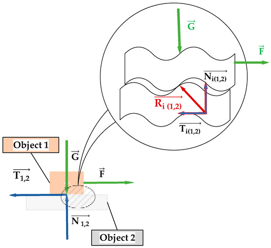
Figure 1.
The friction force between two objects.
- The friction force is proportional to the normal pressure, and the coefficient of friction μ is constant within a certain range of relative velocities and loads.
- Friction depends on the materials and the condition of the contacting surfaces.
- Friction forces always have a direction opposite to the respective relative velocity.
- Static friction forces are greater than kinetic friction forces.
- Friction increases with an increase in the contact time between the surfaces.
—external force acting normally to the contacting surfaces. In the absence of any other external force, it can be equated to the force of gravity with which body 2 acts on body 1.
—axial force that seeks to cause relative motion between objects 1 and 2.
—total reaction at the contact surface between objects 1 and 2.
—total reaction in the i-th contact surface between objects 1 and 2.
—normal reaction in the i-th contact surface between objects 1 and 2.
, —normal response in the friction surfaces at rest/motion.
, —friction forces at rest/motion.
The friction process between the parts of the assembled units is studied in more detail and described in [11].
2.2. Shape-Memory Alloys
The shape recovery effect in “shape memory” alloys is due to a phase change in the alloy crystal structure known as “martensitic transformation” [12]. The transformation depends on the temperature and the load applied to the alloy. There is a definite temperature range above which the alloy is in the austenitic phase and below its lower limit in the martensitic phase.
Austenite is a non-magnetic allotropic form of iron, which exists above the critical eutectoid temperature of 730 °C. Different steel alloys have different eutectoid temperatures. Austenite has a cubic structure of crystal lattice.
Martensite is a phase state of the metal that is obtained by the rapid cooling of austenite. During the martensitic transformation, the atoms rearrange abruptly. Martensite has a centered tetragonal crystal structure, which contributes to its higher hardness and strength.
Martensite does not have good phase equilibrium in the iron–carbon system, so it is easily destroyed by heat and reverts to austenite [13].
The martensite–austenite transformation of the SPF is shown in Figure 2 [14]. The geometric shape of the metal element in its austenitic state (Figure 2a) is the so-called “remembered” or “trained” shape. Upon cooling below a certain temperature, the alloy transitions to the martensitic phase. If no stress is applied to the alloy during cooling, its macroscopic structure remains unchanged. The atoms in their crystal lattice acquire a different (mirror) orientation—“twinning martensite” (Figure 2b). With a small stress applied to this crystal structure, the so-called “deformed martensite” is obtained (Figure 2c). Heating the deformed martensite above the austenitic transformation temperature leads to the reversion of the deformed martensite back into austenite.
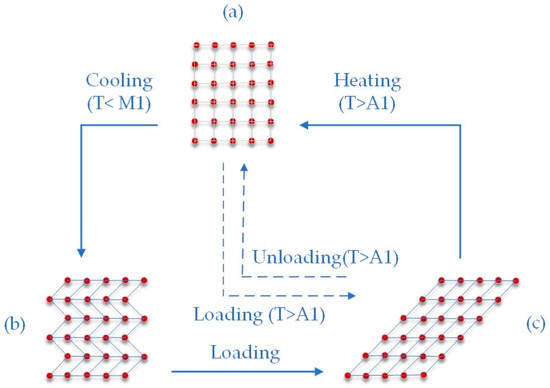
Figure 2.
Martensite–austenite transformation at SPF.
To use SMAs as elements in shrink-fit joints, an alloy must be selected in which the martensitic–austenitic transformation occurs at a temperature lower than the operating temperature of the device.
3. Purpose of the Measurements
The conducted measurements aim to investigate the friction force occurring in the joints as a function of two parameters:
- Substrate diameter, which together with the recovered diameter of the rings defines the amount of interference.
- Surface roughness (Ra) of the part of the shaft where the metal ring is assembled.
The goal is to track the behavior of the above-mentioned parameters in the shrink-fit joints and to determine the limits of their applicability in the field of mechanical engineering.
4. Conducting the Measurements
4.1. UniLok-Type Heat-Shrinkable Ring Used to Create a Shrink-Fit Connection
In this paper, a metal ring made of NiTiNb alloy (Figure 3) was used to form the shrink-fit joint [15]. The characteristics of the ring are listed in Table 1.
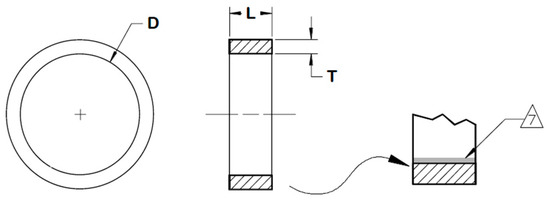
Figure 3.
Shrink ring made of NiTiNb shape-memory alloy.

Table 1.
Heat-shrinkable ring made of shape-memory alloy.
4.2. Description of the Experimental Setup and Conducting of Measurements
The experimental study was conducted on a testing machine with a servo-controlled loading mechanism, which allows precise loading through digital control (Figure 4).
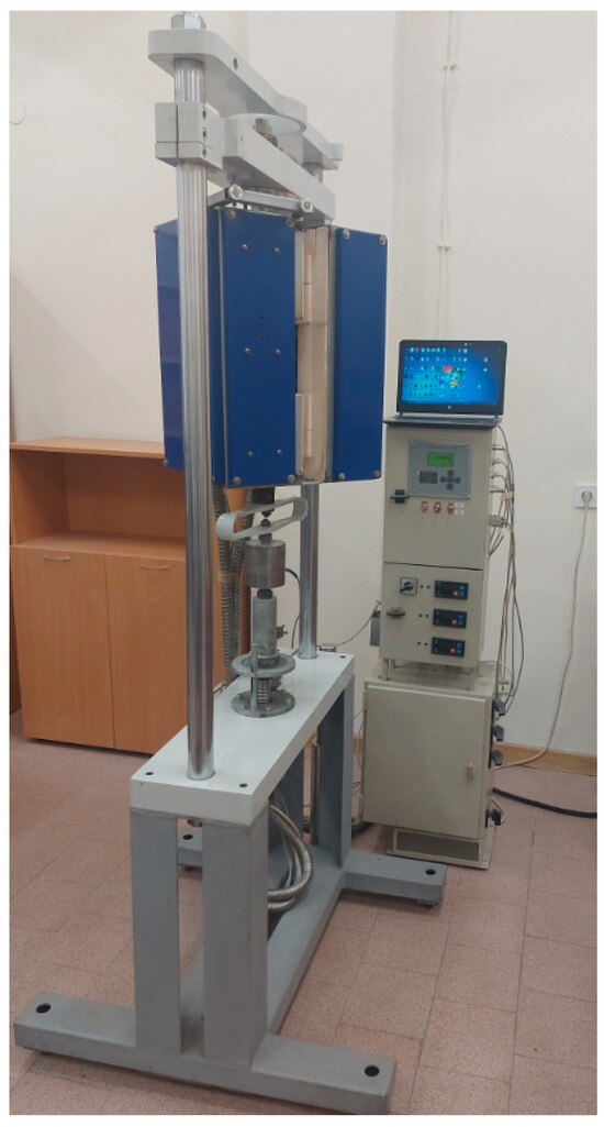
Figure 4.
Testing machine.
For conducting the experimental study, a clamping device shown in Figure 5 was designed and manufactured. It consisted of a lower clamp 1, transitional clamp 2, upper clamp 3, ring 4, and pin 5.
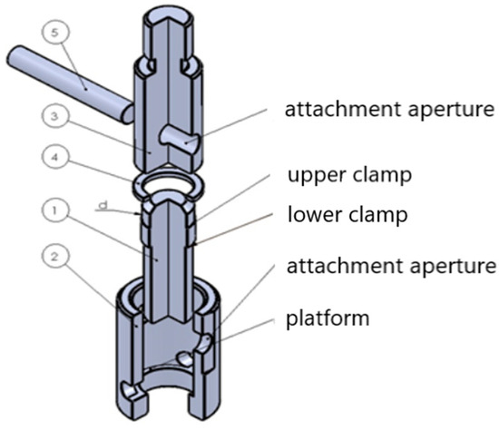
Figure 5.
Clamping device.
The lower clamp of the clamping device was made of S235JR steel [16].
The sequence of the experimental study was as follows:
- The rings were mounted on the lower clamps (Figure 5).
- The lower clamps together with the rings were placed in a heating module (Figure 6). The operating temperature was adjusted to 165 °C and the heating module was switched on. The temperature was controlled with a mercury thermometer. Once the operating temperature was reached, it was held for 30 min and the heating module was switched off. After reaching room temperature, the lower clamps together with the rings were removed from the heating module.
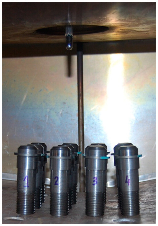 Figure 6. The lower clamps together with the rings inserted in the heating module.
 - The lower clamp, together with the ring pressed against it, was mounted in the transition clamp of the device. The lower clamp was screwed onto the machine’s mobile gripper.
- The upper clamp of the device was mounted on the fixed grip of the machine.
- The transition clamp was lifted and rotated so that the connection holes of the transition and upper clamps stood on the same axis. The pin was then inserted (Figure 7).
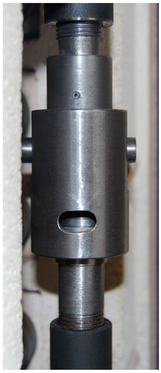 Figure 7. Mounted clamping device.
 - The whole device was subjected to pure tension—the force increased smoothly at a rate of 100 kg/min. If the ring slipped, the test was stopped, and the gripper was unloaded. The force F1 was then recorded.
- Step 6 was repeated consecutively three more times and the axial forces F2, F3, and F4 at which the slip occurred were recorded. At the last load, the ring was removed from the lower clamp.
- Steps 3, 4, 5, 6, and 7 were then repeated.
5. Measurement Results
The axial force (friction force) as a function of the substrate diameter and surface roughness of one of the surfaces in the joint was investigated. The results of the measurements are presented in Table 2.
Table 2.
Relation between the friction force created in the shrink-fit joint, shaft diameter (substrate diameter), and surface roughness.
Figure 8 graphically presents the measurement results.
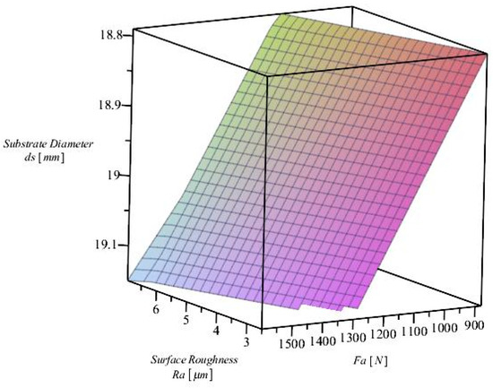
Figure 8.
Graphical representation of the dependence of the friction force created in the shrink-fit joint on the shaft diameter (Substrate Diameter) and the surface roughness.
6. Conclusions
The shrink-fit joints, investigated above, are of interest to the axial fixing of rotating machine parts, e.g., gears or belt pulleys, to the shafts on which they are mounted. This draws attention to the study of the axial force (friction force) as a function of interference and surface roughness.
From the measurements carried out, the following conclusions were drawn:
- The substrate diameter influenced the friction force. This influence is explained by the specific properties of the shape-memory alloy, which define the stress increase during the recovery phase.
- The axial force F1 in eleven out of twelve cases was higher than F2, F3, F4. This can be explained by the fact that friction increases with an increase in the contact time between the surfaces.
- In the classic press-fit joint, achieving the desired interference is associated with additional processing of the surfaces and, hence, with an increase in the cost of the product. The press-fit joint, which includes elements produced from shape-memory alloys, has the advantage of being less sensitive to the quality of the machined surface.
- Concerning the axial force, the limited number of samples does not allow for a general conclusion about the impact of each parameter (substrate diameter and surface roughness) considered in the experiments.
- Rings made of shape-memory alloy can be used for the axial fixation of rotating machine parts. When the parts are assembled, a joint is obtained which has the character of a shrink-fit joint. The resulting clamping force generates the friction force required for the axial fixation of the elements. The use of an SMA facilitates the assembly of the fixing elements. It also leads to a reduction in human error, a factor that is increasingly being investigated and plays a role in the overall risk assessment when developing a new product.
Author Contributions
Conceptualization, V.I.; methodology, V.T. and N.K.; investigation, V.T. and N.K.; resources, E.T.-D.; data curation, E.T.-D.; writing—original draft preparation, E.T.-D.; writing—review and editing, V.I.; visualization, E.T.-D.; supervision, G.T. All authors have read and agreed to the published version of the manuscript.
Funding
This research received no external funding.
Institutional Review Board Statement
Not applicable.
Informed Consent Statement
Not applicable.
Data Availability Statement
The data presented in this study are available on request from the corresponding author. The data are not publicly available due to privacy restrictions.
Acknowledgments
The authors would like to thank the Research and Development sector at the Technical University of Sofia.
Conflicts of Interest
The authors declare no conflicts of interest.
References
- Lexellent, C. Shape-Memory Alloys Handbook; John Wiley & Sons: Hoboken, NJ, USA, 2013. [Google Scholar]
- Wu, M.; Schetky, L. Industrial applications for shape memory alloys. In Proceedings of the International Conference on Shape Memory and Superelastic Technologies, Pacific Grove, CA, USA, 30 April–4 May 2000; pp. 171–182. [Google Scholar]
- Jani, J.M.; Leary, M.; Subic, A.; Gibson, M.A. A review of shape memory alloy research, applications and opportunities. Mater. Des. (1980–2015) 2014, 56, 1078–1113. [Google Scholar] [CrossRef]
- Machado, L.G.; Savi, M.A. Medical applications of shape memory alloys. Braz. J. Med. Biol. Res. 2003, 36, 683–691. [Google Scholar] [CrossRef] [PubMed]
- Chau, E.T.F.; Friend, C.M.; Allen, D.M.; Hora, J.; Webster, J.R. A technical and economic appraisal of shape memory alloys for aerospace applications. Mater. Sci. Eng. A 2006, 438–440, 589–592. [Google Scholar] [CrossRef]
- Otsuka, K.; Wayman, C.M. Shape Memory Materials; Cambridge University Press: Cambridge, UK, 1999. [Google Scholar]
- Lagoudas, D. (Ed.) Shape Memory Alloys—Modeling and Engineering Applications; Springer Science+Business Media, LLC: New York, NY, USA, 2008. [Google Scholar]
- Intrinsic Devices, Inc. Shape Memory Alloy Fasteners. Available online: https://www.intrinsicdevices.com/Shape_Memory_Alloy_Fasteners.pdf (accessed on 12 May 2024).
- Nedev, T.; Lilov, A. Mechanical Engineering; Soft Trade: Sofia, Bulgaria, 2011. [Google Scholar]
- Artobolevski, I. Theory of Mechanisms and Machines 1975; Nauka: Moscow, Russia, 1975. [Google Scholar]
- Kotseva, G.; Georgieva, V.; Gyoshev, S. Investigation of Tribological Parameters of 3D Printed Samples. In Proceedings of the VIII International Scientific Conference Winter Season INDUSTRY 4.0, Borovets, Bulgaria, 6–9 December 2023; pp. 255–258. [Google Scholar]
- Borden, T. Shape-Memory Alloys: Forming a Tight Fit. Mech. Eng. 1991, 113, 67–72. [Google Scholar]
- Todorov, T.; Nikolov, R.; Ralev, Y. Experimental Investigations of Shape Memory Alloys by Specialized Evaluation Setup Bulg. J. Eng. Des. 2016. [Google Scholar]
- Topalski, S. Martensitic Transformation by Deformation in Monocrystalline Cu-Al-Ni Shape Memory Alloy; Scientific Papers of University of Russe; University of Russe: Russe, Bulgaria, 2008; Volume 47, Series 2. [Google Scholar]
- Intrinsic Devices. Shape Memory Fasteners. Available online: https://intrinsicdevices.com (accessed on 12 May 2024).
- Dimitrov, L. Principles of Mechanical Engineering Design. Design of Mechanical Components; Heron Press: Sofia, UK, 2009. [Google Scholar]
Disclaimer/Publisher’s Note: The statements, opinions and data contained in all publications are solely those of the individual author(s) and contributor(s) and not of MDPI and/or the editor(s). MDPI and/or the editor(s) disclaim responsibility for any injury to people or property resulting from any ideas, methods, instructions or products referred to in the content. |
© 2024 by the authors. Licensee MDPI, Basel, Switzerland. This article is an open access article distributed under the terms and conditions of the Creative Commons Attribution (CC BY) license (https://creativecommons.org/licenses/by/4.0/).