Abstract
The cutting speed of laser cutting is predicted to affect the roughness of its object. However, its roughness characteristics still need to be determined to consider whether it is tolerant. The aspects of cutting products are studied intensely. Specific cutting styles with different plates like Eser thick versus velocity of the cut varied, affecting the fineness of surface cutting. However, a monitor showing frequency and period explained the more significant roughness. Those are predicted to be straightforward for checking samples. Using CMM and the Surface Roughness Tester, the cutting parameter and its process can be recommended for future applications. The brief used Eser plate cutting using CNC laser cutting with thicknesses of 3 mm, 4 mm, and 5 mm with cutting speeds of 1 m/min, 1.4 m/min, and 2 m/min. The best cutting speed was 2 m/min for a plate thickness of 3 mm, with an accuracy level of 98% and 98.51%, while the lowest Ra value was 6.51 µm. The plate thickness was 4 mm, the accuracy level was 98.05% and 98.77%, and the lowest Ra value was 4.183 µm. The plate thickness was 5 mm with an accuracy level of 97.7% and 97.99% and Ra of 8.995 µm. In the laser process, the thicker an object is, the lower its accuracy. In addition, the frequency of roughness sensitivity detection impacts more than its period during a standard operation.
1. Introduction
A CNC machine is an automation system with commands programmed and stored on storage media [1]. The CNC Laser Cutting machine combines CNC and laser technology, a cutter capable of cutting sheets with complex shapes that require precision in processing [2]. CNC machines have two or more directions of movement called axes. Movements on the axis include linear movement, which is a straight line, or circular movement, which is a circular movement. One of the specifications showing a CNC machine’s complex work is its many axes and the combination of movements on each axis [3]. The working principle of laser cutting is to direct a high-power laser beam at the material to be cut via a computer [4]. The CNC is a laser machine that uses O2 gas. This gas is used in steel cutting [5].
The machining process is carried out on the material using the parameters of the laser beam focus point, cutting gas pressure, and cutting speed [6]. Highly focused heat energy when cutting metal using laser cutting can increase the value of the cutting width (kerf width) and cause changes in the hardness of the metal material. The influence of the cutting width (kerf width) and hardness on the cutting process using laser cutting provides disadvantages because if the cutting width is too large, the wasted material will increase, and the accuracy of the cutting size decreases so that the cutting results do not match the design or drawing [7]. The CNC machining begins with designing objects using Computer-Aided Design (CAD) software. Then, it continues into the manufacturing process using Computer-Aided Manufacturing (CAM)-based software, an application technology that uses computer software and machines to facilitate and automate the manufacturing process [8].
Manufacturing production cannot be separated from cutting raw metal and non-metal materials [9]. Even though the metal-cutting process is most frequently used in manufacturing. Cutting is critical because it will determine the material’s quality in the subsequent process. Quality products, too; it is necessary to have sturdy but light products, so non-metal choices, for instance, acrylic [10]. The minimum product roughness can be achieved by setting the influencing parameters, namely the focus point of the laser beam, cutting gas pressure, and cutting speed [11]. Laser-cutting machines have various advantages in manufacturing technology because they can receive data directly from a computer so that the cutting process can run automatically. CNC laser cutting can also be used to cut and engrave [12], showing the work’s details.
The CNC laser machine can conduct two machining processes: cutting and engraving. The cutting process is used to cut the material, while the engraving process is used to scratch the material’s surface so that the result becomes like a carving [13]. By setting the influencing parameters, the optimum product results are influenced by the focus point of the laser beam, cutting gas pressure, and cutting speed. The cutting speed influences the optimum cutting results at the right thickness [14].
CNC laser cutting machines are increasingly widely used for industry manufacturing and the craft industry in small and medium businesses such as furniture and home interiors. Meanwhile, designing a CNC laser cutting machine for laboratory and small industrial scales is now relatively more straightforward considering technological developments and the ease of obtaining standard components, supporting components, and supporting software, which can be purchased more cheaply [15]. In carrying out production activities, the maintenance system has an important role. Each machine must be well maintained to ensure the production process can run smoothly according to the expectations of all companies [16]. CNC Laser cutting is a modern machining process for cutting sheet metal from hard materials with complex patterns and produces relatively fast processing times. This laser-cutting process is like gas pressure, cutting speed, and laser power is expected to improve the products’ quality [17].
2. Materials and Methods
Laser cutting is a precise and efficient technique used in various industries to cut and shape different materials. The process involves using a highly focused laser beam that melts, vaporizes, or burns the material, resulting in intricate cuts and designs. The main components of a laser cutting system include a laser source, focusing optics, and a computer-controlled motion system. Laser cutting can be done using the O2 laser or fiber laser research methods, each with advantages and applications.
CNC Laser Cutting Machine PT. Pura Barutama is the primary tool in this research. This machine is used to cut plates using laser cutting technology according to specified speed variations. AutoCAD 2010 software is used to create design and cutting programs that will be used on CNC laser cutting machines. AutoCAD 2010 allows precise and accurate designs and facilitates the creation of cutting programs according to speed variations of 1 m/min, 1.4 m/min, and 2 m/min. Using the Cypcut Laser Cutting System as control software allows setting the cutting parameters, including cutting speed, and ensures efficient and accurate CNC laser cutting machine operation. A simple design of the object to be cut can be seen in Figure 1.
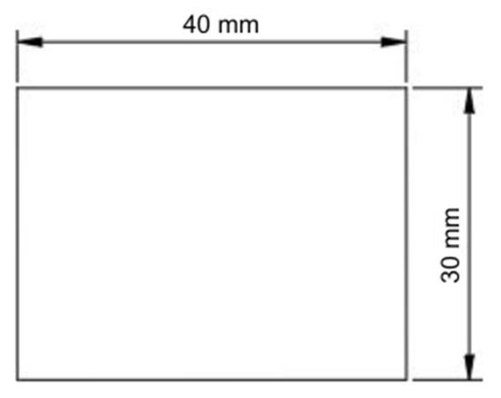
Figure 1.
Image design for cutting.
Kerf width theory is a concept that refers to the width of material removed or cut by a cutting tool, such as a CNC laser cutting machine. Using kerf width theory, we can relate the measurement results from the CMM and Surface Roughness Tester to the material removed during the cutting process. CMM allows us to understand the final dimensions of the cut material and its surface quality and ensure that the cut results meet the desired specifications. Thus, kerf width theory can be the basis for linking material processing using a CNC laser cutting machine with quality measurement and analysis using a CMM and Surface Roughness Tester.
Laser cutting can be done on various materials, such as metal, plastic, wood, and textiles. However, the compatibility of materials with laser cutting depends on factors such as thickness, composition, and reflectivity. Each material has its advantages and limitations when cut with a laser. In this research, we used the JIS G3101 SS400 Eser plate, which is often used in various construction projects, machine manufacturing, and the automotive industry because of its strong and durable characteristics. The thickness of the ice plate is 3 mm, 4 mm, and 5 mm.
Various techniques can be used in laser cutting, such as vector cutting, raster engraving, and etching. It also uses the parameters of cut height 0.8 mm, lift height 25 mm, cut power 100%, cut frequency 5000 Hz, cut focus 4.3 mm, cut oxygen gas, and cut pressure 0.8 Bar. First, cut height is the distance between the plate surface and the laser nozzle tip, which must be set precisely to ensure optimal laser focus. Then, lift height is the vertical distance when the machine moves across the cutting area, which is essential to prevent damage and smooth movement. Cut power regulates the laser’s intensity, affecting different materials’ speed, accuracy, and cutting ability. Next, cut frequency determines the number of laser pulses per second, affecting the speed and quality of the cut. Cut focus holds the length of the nozzle to the surface, impacting the accuracy and quality of the amount. Cut focus regulates the distance of the nozzle to the surface, affecting the accuracy and quality of the cut. The final parameters are cut gas and cut pressure, where a cutting gas such as oxygen helps remove molten material, and the gas pressure is regulated for cutting efficiency. The right one is essential to achieve the desired results. Safety precautions, including good ventilation and eye protection, must be followed when operating a laser-cutting machine. Regular maintenance is also essential for optimal machine performance and long life.
3. Results and Discussion
Laser cutting applications are broad and varied, spanning manufacturing, automotive, aerospace, jewelry, and many more industries. Laser cutting enables high precision, complex designs, and fast production times. Although laser cutting offers many advantages over traditional cutting methods, it has limitations, such as a limited thickness capacity. The results of cutting laser plates with thicknesses of 3 mm, 4 mm, and 5 mm using various cutting speeds of 1 m/min, 1.4 m/min, and 2 m/min in accuracy testing using a CMM and roughness using a Surface Roughness Tester are depicted in Figure 2. The following discussion will highlight this.
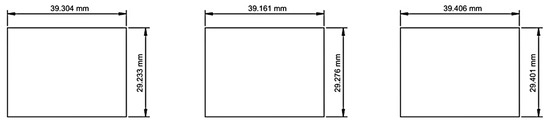
Figure 2.
Results of a cutting 3 mm plate using speeds of 1 m/min, 1.4 m/min, and 2 m/min.
Table 1 shows the percentage of size precision due to the laser cutting machine. It shows that the width and length accuracy is up to 98.5%. It was still evident that this machine needed to be more precise, as errors remained.

Table 1.
The percentage of precision 3 mm cuts.
More clearly, from the results, the best cutting speed for a plate thickness of 3 mm is 2 m/min. As evidenced by its cutting speed, the reduction in dimensions of the cutting results is the smallest. The difference in width is just 0.599 mm, and the length is 0.594 mm, with 98% and 98.51% precision levels. The characteristics of roughness are shown in Figure 3.
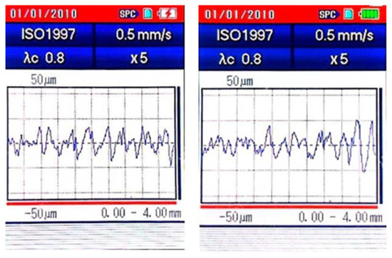
Figure 3.
The image of the 3 mm plate roughness at a cutting speed of 2 m/min (measured on Standard—ISO 1997 [18]; 0.5 mm/s; λc = 0.8; X = 5; Gauss).
More details about the effect of the moving velocity spindle’s Speed of laser cutting are shown in Figure 4. The results of the surface roughness measurements expressed in Ra values of three samples of 3 mm thick plate cutting objects showed the highest Ra value of 24.719 µm and the lowest Ra of 6.51 µm.
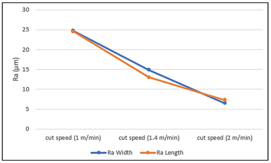
Figure 4.
The effect of moving the velocity spindle’s laser cutting speed at 3 mm thick.
Moreover, by analyzing the Ra values, the higher cutting speed creates a smoother surface than the lower Speed. The following will discuss other thicknesses of materials, as shown in Figure 5, which shows the effect of various speeds on a plate thickness of 4 mm by using CMM to make sense of the analysis. It is evidenced more clearly in Table 2.
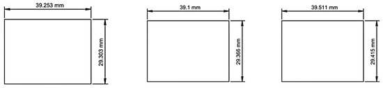
Figure 5.
Results of the cutting 4 mm plate using speeds of 1 m/min, 1.4 m/min, and 2 m/min.
Table 2.
The percentage of precision 4 mm cuts.
From the results obtained, the best cutting speed for a plate thickness of 4 mm is 2 m/min. With this cutting speed, the reduction in dimensions of the cutting results is the smallest. The difference in width is 0.585 mm, and length is 0.489 mm, with precision levels of 98.05% and 98.77%. Figure 6 shows the roughness captured by using the Surface Roughness Tester. It offers a more significant period than Figure 3 of the Surface Roughness Tester, but not for its frequency.
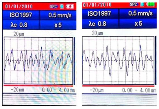
Figure 6.
Plate roughness for 4 mm at cutting speed 2 m/min (measured on Standard—ISO 1997 [18]; 0.5 mm/s; λc = 0.8; X = 5; Gauss).
Lastly, for comparison, there is a 5 mm plate thickness cut with a laser with various velocities, like the previous ones. Figure 7 shows that the Speed significantly affects the object dimensions.
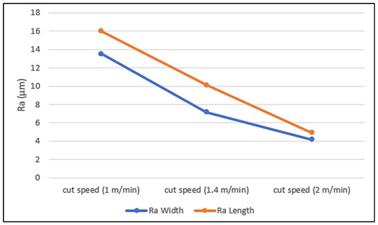
Figure 7.
The effect of moving the velocity spindle’s laser cutting speed at 4 mm thick.
In addition, an analysis of the results of the surface roughness measurements stated in Ra values from three samples of plate-cutting objects with a thickness of 5 mm showed variations. The highest Ra value was 16.002 µm, while the lowest was 4.183 µm. The lower the Ra value, the smoother the object’s surface. The measure of the cut in CMM is shown in Figure 8.
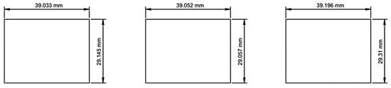
Figure 8.
Results of the cutting 5 mm plate using speeds of 1 m/min, 1.4 m/min, and 2 m/min.
Table 3 shows that the higher the thickness of an impact, the more significant the roughness, and the roughness reverses.
Table 3.
The percentage of precision 5 mm cuts.
From the results obtained, the best cutting speed for a plate thickness of 5 mm was 2 m/min. With this cutting speed, the reduction in dimensions of the cutting results was the most significant. The difference in width was 0.69 mm, and the length was 0.804 mm, the highest compared to the previous 3 and 4 mm thicknesses, with precision levels of 97.7% and 97.99%. Figure 9 tries to figure out the effect of the frequency, and while nearly identical, it shows the frequency more often than in Figure 6.
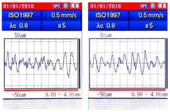
Figure 9.
Plate roughness of 5 mm at a cutting speed of 2 m/min (measured on Standard—ISO 1997 [18]; 0.5 mm/s; λc = 0.8; X = 5; Gauss).
Figure 10 describes the effect of the spindle’s moving rates on the graph. It also shows the correlation between the cutting speed and roughness in Ra.
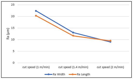
Figure 10.
The effect of moving the velocity spindle’s laser cutting speed at 5 mm thick.
The surface roughness measurement data expressed in Ra values from three samples of plate-cutting objects with a thickness of 5 mm showed variations. The highest value recorded was Ra 22.365 µm, while the lowest was Ra 8.995 µm. As predicted, the lower the Ra value, the smoother the object’s surface. From the data presented as a prediction, the roughness or smoothness of the character in the Surface Roughness Tester was shown in frequency mode rather than its period.
4. Conclusions
Based on research, this review states that laser cutting is a precise and efficient technique used in various industries to cut and shape multiple materials, but it needs to be corrected. More precisely, the evidence detected in the frequency by the Surface Roughness Tester is more tangible than its period according to the following evidence:
In brief, from the results obtained, the best cutting speed for all was 2 m/min for a plate thickness of 3 mm with a difference in width of 0.599 mm and length of 0.594 mm, with precision levels of 98% and 98.51%, and the roughness showed the highest Ra value of 24.719 µm and the lowest Ra of 6.51 µm. At a plate thickness of 4 mm, the difference in width was 0.585 mm, and the length was 0.489 mm, with precision levels of 98.05% and 98.77%. The highest Ra roughness value was 16.002 µm, while the lowest was 4.183 µm. For the 5 mm plate thickness, there was a difference between 0.69 mm in width and 0.804 mm in length, with precision levels of 97.7% and 97.99%. The highest roughness value was Ra 22.365 µm, while the lowest was Ra 8.995 µm.
If there was a thicker material, the potential to rough the surface was higher at various cutter speeds.
Author Contributions
Conceptualization, R.G.G. and M.R.P.; methodology, R.G.G. and M.R.P.; software, R.G.G.; validation, R.G.G. and M.R.P.; formal analysis, R.G.G. and M.R.P.; investigation, R.G.G. and M.R.P.; resources, R.G.G. and M.R.P.; data curation, M.R.P.; writing—original draft preparation, R.G.G. and M.R.P.; writing—review and editing, R.G.G. and M.R.P.; visualization, R.G.G.; supervision, M.R.P.; project administration, R.G.G. and M.R.P.; funding acquisition, R.G.G. and M.R.P. All authors have read and agreed to the published version of the manuscript.
Funding
This research received no external funding.
Institutional Review Board Statement
Not applicable.
Informed Consent Statement
Not applicable.
Data Availability Statement
The raw data supporting the conclusions of this article will be made available by the authors on request.
Acknowledgments
We express our deepest gratitude to PT. Pura Barutama, beholden, for granting permission to use the related data and information in our research on plate cutting using CNC laser cutting. The permission granted through number 028/D.2-VII/PKKM/IX/2022 is significant for the smooth running of our research and P.T.’s contribution and support. This collaboration can bring benefits to both parties. Grateful for the opportunity.
Conflicts of Interest
The authors declare no conflicts of interest.
References
- Fatriyana, M. Cnc Program and Programming of Cnc Machine. J. Mech. Sci. Eng. 2020, 7, 019–023. [Google Scholar] [CrossRef]
- Li, L.; Wu, Z.; Zhang, Z.; Zhang, Y. An Optimization Method for CNC Laser Combination Cutting of Irregular Plate Remainders. Coatings 2023, 13, 914. [Google Scholar] [CrossRef]
- Agarwal, S.; Ratnaparkhi, P.; Kori, R.P. Arduino Based CNC Drawing Machine. Int. J. Res. Sci. Eng. 2020, 1, 145–148. [Google Scholar]
- Costa Rodrigues, G.; Vanhove, H.; Duflou, J.R. Direct diode lasers for industrial laser cutting: A performance comparison with conventional fiber and CO2 technologies. Phys. Procedia 2014, 56, 901–908. [Google Scholar] [CrossRef]
- Powell, J.; Petring, D.; Kumar, R.V.; Al-Mashikhi, S.O.; Kaplan, A.F.H.; Voisey, K.T. Laser-oxygen cutting of mild steel: The thermodynamics of the oxidation reaction. J. Phys. D Appl. Phys. 2009, 42, 015504. [Google Scholar] [CrossRef]
- Le, G.-N.; Hoang, A.-T.; Nguyen, D.-V.; Nguyen, M.-T.; Nguyen, Q.-H. A Method to Determine Machining Parameters for Laser Cutting Machine Using Numerical Simulation. Int. J. Sci. Eng. Sci. 2018, 2, 65–68. [Google Scholar]
- Yilbas, B.S.; Shaukat, M.M.; Ashraf, F. Laser cutting of various materials: Kerf width size analysis and life cycle assessment of cutting process. Opt. Laser Technol. 2017, 93, 67–73. [Google Scholar] [CrossRef]
- Khalid, R.; Al, H.; Rameshkumar, G.R. Design and Fabrication of 3-Axis Computer Numerical Control (CNC) Laser Cutter. Int. J. Multidiciplinary Sci. Eng. 2016, 7, 7–16. [Google Scholar]
- Naik, B.M.; Arief, S.; Nachiketha, V.; Babu, K.K.; Tirumani, V.D. Laser Cutting Technique. Int. J. Mod. Trends Sci. Technol. 2022, 8, 32–37. [Google Scholar]
- Oktatian, E.; Rosyidi, C.N.; Pujiyanto, E.; Oktatian, E.M. Optimization of CNC CO2 Laser Cutting Process Parameters on Acrylic Cutting Using Taguchi Grey Relational Analysis and Response Surface Methodology. Res. Sq. 2021; preprint. [Google Scholar] [CrossRef]
- Rakasita, R.; Karuniawan, B.W.; Juniani, A.I. Optimasi Parameter Mesin Laser Cutting Terhadap Kekasaran Dan Laju Pemotongan Pada Sus 316L Menggunakan Taguchi Grey Relational Analysis Method. J. Tek. Ind. 2016, 11, 97. [Google Scholar] [CrossRef][Green Version]
- Sridutt, H.R.; Sachin, M.; Pramod, M.; Surendra, M.; Katti, B.B.; Chandrakumar, C. Fabication and Analysis of Cnc Laser Engraving on Different Materials. J. Emerg. Technol. Innov. Res. 2019, 6, 228–230. [Google Scholar]
- Kumar, P.J.; Tarun, A.S.S.; Gowtham, M.; Rao, P.T.; Yashwanth, G. Design and fabrication of portable laser cutting and engraving machine. Int. J. Eng. Technol. 2018, 7, 570–573. [Google Scholar] [CrossRef][Green Version]
- Alsaadawy, M.; Dewidar, M.; Said, A.; Maher, I.; Shehabeldeen, T.A. A comprehensive review of studying the influence of laser cutting parameters on surface and kerf quality of metals. J. Adv. Manuf. Technol. 2024, 130, 1039–1074. [Google Scholar] [CrossRef]
- STYLECNC CHINA. The Benefits of Laser Cutting Laser Cutting Definition. 2019. Available online: https://www.academia.edu/40967998/The_Benefits_of_Laser_Cutting_Laser_Cutting_Definition (accessed on 26 February 2024).
- Thombansen, U.; Hermanns, T.; Stoyanov, S. Setup and maintenance of manufacturing quality in CO2 laser cutting. Procedia CIRP 2014, 20, 98–102. [Google Scholar] [CrossRef]
- Shelke, R.D.; Chavan, U.H. Optimisation of sheet metal cutting parameters of laser beam machine. Int. J. Eng. Sci. Res. Technol. 2018, 7, 474–484. [Google Scholar]
- ISO 4287:1997; Geometrical Product Specifications (GPS)—Surface Texture: Profile Method–Terms, Definitions and Surface Texture Parameters. International Organization for Standardization: Geneve, Switzerland, 1 April 1997.


Disclaimer/Publisher’s Note: The statements, opinions and data contained in all publications are solely those of the individual author(s) and contributor(s) and not of MDPI and/or the editor(s). MDPI and/or the editor(s) disclaim responsibility for any injury to people or property resulting from any ideas, methods, instructions or products referred to in the content. |
© 2024 by the authors. Licensee MDPI, Basel, Switzerland. This article is an open access article distributed under the terms and conditions of the Creative Commons Attribution (CC BY) license (https://creativecommons.org/licenses/by/4.0/).