Proceeding Paper

Performance Analysis of a Nine-Phase Squirrel Cage Induction Motor under Faulty Conditions †

Department of Electrical and Electronic Engineering Technology, University of Johannesburg, Auckland Park, Johannesburg 2006, South Africa
*
Author to whom correspondence should be addressed.
Presented at the 4th International Conference on Communications, Information, Electronic and Energy Systems (CIEES 2023), Plovdiv, Bulgaria, 23–25 November 2023.
Eng. Proc. 2024, 60(1), 14; https://doi.org/10.3390/engproc2024060014
Published: 10 January 2024

Abstract

:
This paper evaluates the performance of an inverter-fed nine-phase squirrel cage induction motor (SCIM) under faulty conditions. The induction motor’s stator core of the conventional National Electrical Manufacturers Association (NEMA) frame size of 90L has been rewound to accommodate coils that form the nine-phase windings. The prototyped nine-phase SCIM drive has been tested for transient and steady-state capabilities for well-conditioned and defective functioning. The open-phase-winding faults are caused by fuses opening during an imposed short circuit. The experimental results evidenced that the nine-phase induction motor drive can operate under faulty conditions while minimizing the gravity of defective functioning. This premise has positioned the nine-phase SCIM drive as a strong candidate in applications where fault tolerance is a must, and the motor may be required to continue operating temporarily under faulty conditions until maintenance is in effect.

1. Introduction

Multi-phase drives provide various benefits over three-phase drives, including the following: high reliability, excellent torque density, reduction of power per phase, and higher fault tolerance [1,2]. These benefits, notably higher fault tolerance, make the multi-phase machines suitable for electric vehicle traction, airplanes, submarine propulsion, and any other applications that require high-power density and fault tolerance [2]. Additionally, there is excellent attentiveness to energy power generation setups having a higher order number of phases, most notably in grid- and off-grid-connected wind turbine systems [3]. As a traction motor, a nine-phase permanent magnet (PM) motor drive system was developed for an ultra-high-speed elevator that set a world record [4].
The expense and risk of service interruptions make reliable electric drives an absolute need in mission-critical industrial applications [5]. In the event of a short-circuit or open stator phase, multi-phase electric machines have the benefit of being able to start and operate with a tolerable reduction in performance [6,7]. Even though the aim is to prevent any induction motor failure, measures for achieving fault-tolerant functioning must be used if one does occur. A questionnaire survey was done to ascertain the industry’s requirements and expectations for reliability in power electronic drives [8]. The study included responses from several prominent semiconductor manufacturers and end users in the electric vehicle and utility power sectors, among others [8]. According to the analysis, the most fragile components were power semiconductor devices [8]. The principal stresses discovered were those generated by external factors and temporary and excessive load currents [8]. These must be considered when designing and operating power electronic systems.
Faults in power devices keep them in an on or off state [9]. To avoid a full loss of the drive, the power converter might disconnect the faulty phase and keep the current flowing in the remaining healthy phases while losing specific control abilities. Consequently, the electrical drive might be considered a whole different system after a malfunction due to the post-fault change in its design [9]. Component failure rates in induction motors, on the other hand, are generally about 38% of the faults pertaining to the stator, 10% to the rotor, 40% to the bearings, and the other 12% are unrelated [10]. Inverter or motor problems may cause the stator currents and voltages to become unbalanced, the line currents to be more distorted, the motor’s average torque to drop, the torque pulsations to increase, the overall system to overheat, and the efficiency to degrade [10].
Short-circuits in switches, stator windings, and stator winding short-circuit turns all occur frequently in motor drives [11]. However, in recent years, open-circuit fault tolerance has been the most extensively researched case, whereas other forms of fault have received less attention [11]. Fault-tolerant functioning in the presence of short-circuit defectiveness is much more onerous, and despite its frequent occurrence, it has yet to be given more academic scrutiny to date [11].
This paper discusses several failures that may occur with an inverter-fed, nine-phase SCIM drive. The faults include one open phase and two neighboring and non-neighboring open phases. It is worth noting that fast-acting fuses induced the open-phase faults. This paper is structured as follows. Section 2 of this paper provides a brief background on metal-oxide semiconductor field-effect transistor (MOSFET) switches and SCIM stator winding faults. In Section 3, the experimental measurement setup is presented and discussed, and the analysis of measured results for well-conditioned and defective functioning is reported in Section 4. Key findings are summarized in Section 5.

2. Background on MOSFET Switch and Stator Winding Faults

2.1. A MOSFET Disconnected Circuit

A MOSFET disconnected circuit defect does not instantly damage the power converter, but it may lead to other converter failures [10]. During the first half of a period, the phase current will be 0 A if just one MOSFET is open-circuited. The current will have a DC component, which will generate braking torque and uneven loads in the devices on one inverter leg. The frequency of the stator currents determines the pulsation frequency of the torque, which may cause mechanical issues like resonance. There will be twice as many pulses of torque as currents if one phase is open [10]. An analysis of a nine-phase SCIM drive operating with disconnected MOSFETs and open-phase defectiveness is reported in [12]. In the latter, the phase current was not entirely zero even if both MOSFETs of an inverter leg were disconnected, with the flyback diodes still in operation. As a result of the back electromotive force and flyback diodes of the disabled MOSFETs, the current may return to either the positive or negative dc-link, depending on the neutral point voltage [2,13]. The motor’s neutral point voltage will be affected, and the drive’s configuration will be continually commuting because of the uncontrolled current. In situations where the drive is operating below its peak post-fault rating, flyback diodes have limited impact [9]. Greater values of the load torque or fault detection latency exacerbate this decrement in performance; however, the experimental findings in [13] show that it only affects a tiny portion of the total functioning. Because of the flyback diode stator currents, torque generation is marginally reduced, and copper losses are increased.

2.2. MOSFET Short-Circuit Defectiveness

A MOSFET short-circuit defect, in contrast to an open-phase one, may result in the failure of the failed MOSFET as well as the remaining MOSFETs and other circuit components due to the excessive and uncontrolled current that is generated. Detection periods for short-circuit failures are often much shorter than for open-circuit failures [14,15]. Depending on whether the upper or lower MOSFET failed, the phase voltage is locked to the DC-link bus voltage when it shorts out (lower MOSFET failed). The stator currents can only be restricted by the stator resistance because of the DC component in the voltage.
Using a rapid action fuse in series with each switching device, inverter leg, or phase winding to induce a disconnected-circuit scenario is recommended in [16,17,18,19] to reduce short-circuit current. As with open-phase defectiveness, the drive should be controlled by the remaining healthy phases. The study of a short-circuit failure in a nine-phase SCIM drive is reported in [20]. Using a balanced short circuit following a short-circuit defect of the converter or the motor is recommended as a post-fault control approach [21]. Instead of using the defective short-circuited set to counteract the brake torque, the drive should be powered by the healthy three-phase set.
A short-circuit fault in an inverter switch is not tolerated by star-connected equipment, according to work reported in [12]. Open-ended winding machines and dual-inverter power supplies have been suggested in certain studies as ways to increase MOSFET fault tolerance [22,23,24]. MOSFETs’ short-circuit failures have been the subject of much more study than open-circuit faults and mature fault-tolerant solutions. Open MOSFETs seem to be the most prevalent cause of MOSFET wire bond module failures, according to many studies [25,26,27,28,29]. Short-circuit failures in semiconductor power devices, on the other hand, are more common than open-circuit faults, according to [29]. The work in [29] suggests that open-circuit winding failures are infrequent compared to short-circuit stator defects [29].
Because of the lack of wire bonding and the direct link between the die and metal contacts, press-pack MOSFETs fail catastrophically and fail completely. The press-pack MOSFETs, however, might open-circuit in due course because of the relatedness between molten aluminum (Al), molybdenum (Mo), and silicon (Si), resulting in diverse alloys with low conductivity [30,31]. Short-circuit failures in the case of semiconductor device degradation are a recognized need for continued development of MOSFET modules in electric power systems. The reason for this is that, with MOSFET modules connected in series, even if one or more of the redundant power modules fails, the string will still function properly as a whole. There are scheduled interruptions for maintenance, and these failing modules may be replaced at the next one. It is challenging to forecast and confirm the usual failure mode since the power device might fail in short-circuit, open-circuit, or be ruined depending on the energy associated with the device [32]. That is why the literature does not have enough data to draw any firm conclusions about MOSFET failure modes or even an average proportion of MOSFET failure modes.

2.3. Stator Winding Faults

Winding short circuits are among the most dangerous of all winding defects. Overheating, transient overvoltage stress, excessive mechanical stress, and other factors can contribute to the loss of insulation [30,31]. Due to inadequate turn-to-turn insulation, over 80% of all stators’ electrical failures are caused by this problem.
Insulation failures are often preceded by high currents caused by inter-turn short circuits. Short-circuit currents generate enormous heat, which burns the insulation in the nearby windings, resulting in a short circuit. In the event of a stator core-to-ground insulation breakdown, the motor may be permanently destroyed. In the case of tiny, low-voltage motors, this sequence typically takes 20–60 s to complete. High voltages between neighboring rotations in medium-voltage motors may accelerate this process [14]. As the number of shorted turns, their location, and the speed of a machine increase, so does the amount of circulating current.
Partially shorted coils in permanent magnet synchronous machines may result in substantially higher short-circuit currents [32]. Because the resistance of only one shorted turn would restrict the fault current, this seems to be the most severe example of short-circuiting. Practical and easy methods to reduce fault current include applying a short circuit to the ruined winding [29,30]. Shorting all the turns in a winding causes the magnetic flux in the turns that are fine to point in the reverse direction of the d-axis. That means that short-circuit current in defective turns may be minimized by reducing the overall magnetic flux along that tooth [31]. A machine designed with a concentrated stator winding, which usually provides fault-tolerant abilities such as thermal, magnetic, and mechanical separations among the phases, may be a good fit [31].
Auxiliary switches were installed in the stator windings of a five-phase PM machine to transition from a short-circuit faulty operation to an open-phase faulty operation, with the five-phase windings configured in a combined star-pentagon configuration [24]. The five-phase PM motor examined in [24] features a design that provides fault tolerance abilities with little integration between the phase windings, and the short-circuited phase current is restricted by the winding impedance with no impact whatsoever on the remaining healthy phases. A short-circuit defect, such as a MOSFET short-circuit, has been noted as a possible strategy by researchers in the literature.

3. Experimental Measurements

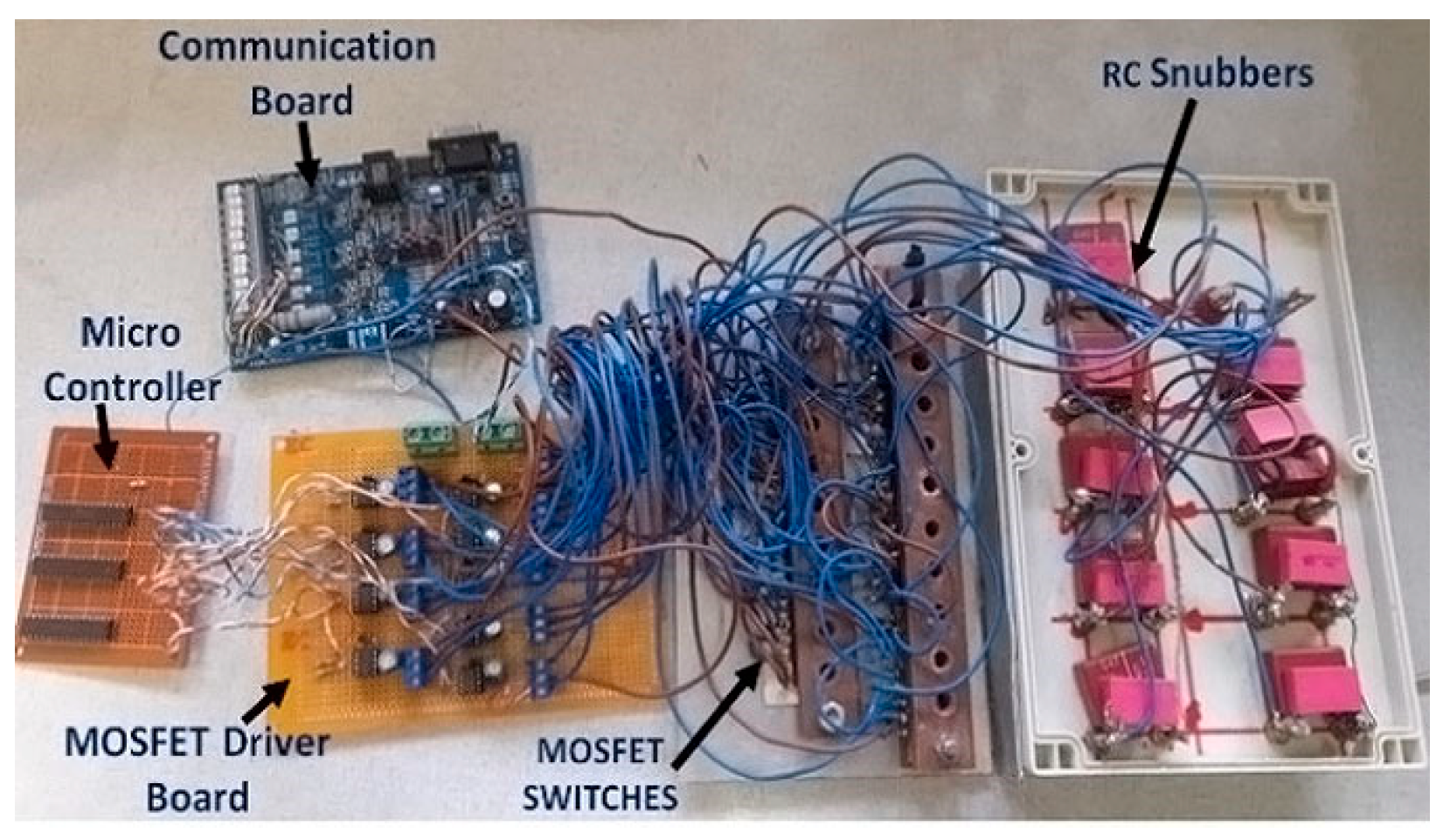
Figure 1 shows the experimental rig photo in a laboratory setup. Figure 2a exhibits the rewound 90L stator NEMA frame with nine-phase winding connected on a shared neutral point, and Figure 2b shows the squirrel cage rotor. Figure 3 illustrates the main components of the 5 kVA, nine-phase inverter with a control system based on Arduino Uno Mega.
A three-phase asynchronous motor rated at 7.5 kW is used as a mechanical load for the prototype nine-phase SCIM. A torque transducer of type DR-3000-P manufactured by Lorenz Messtechnik in Alfdorf, Germany was used to measure the mechanical parameters of interest. The Dranetz PowerVisa 4400 power analyzer, manufactured by Dranetz in Edison, NJ, USA and the Hantek DSO4004C Series digital oscilloscope, manufactured by Hantek, in Qingdao, Shandong, China were used to analyze the electrical performance parameters. The nine-phase SCIM motor has star-connected stator windings, and its neutral is joined to the DC mid-point of the voltage source inverter (VSI). The sinusoidal PWM has a switching frequency of 4 kHz. This switching frequency has been employed in all studies, and the machine operated at rated load. The DC-Bus voltage of 140 V was employed during the tests. Due to the neutral being connected to the DC-bus mid-point, the phase-to-neutral RMS voltage was 50 V. Table 1 gives the specifications, ratings, and parameters of the nine-phase SCIM drive system.

4. Measured Results and Discussion

4.1. Healthy Operation

The nine-phase SCIM stator voltages are given in Figure 4a. The voltages were measured across the terminal of a phase winding and the neutral point. The nine-phase voltages are balanced and have an RMS value of ±49.50 V. The phase voltages are shifted from one another by 40 degrees electric. The full period of each phase-voltage waveform in Figure 4a is observed to be 0.02 s, which corresponds to a frequency of 50 Hz. The machine’s balanced currents may be seen in Figure 4b. The PWM ripple was eliminated by resampling these currents at the converter switching frequency. The SCIM was run at nameplate values. The steady-state torque profile under healthy operation is shown in Figure 5. The average shaft torque of 26 Nm with a torque ripple of 53.84% was recorded when the nine-phase induction motor drive was under healthy operation. The high torque ripple noted in the torque characteristics may, for instance, be reduced by selecting the correct voltage vector to switch the nine-phase inverter. This can be achieved by opting for an appropriate controller to replace the Arduino-Uno-Mega-based control system used in this study. The distortion of the voltage and current waveforms is notable in Figure 4a,b, respectively.

4.2. Faulty Operation with Phase A Shorted and Open by Fast Active Fuse

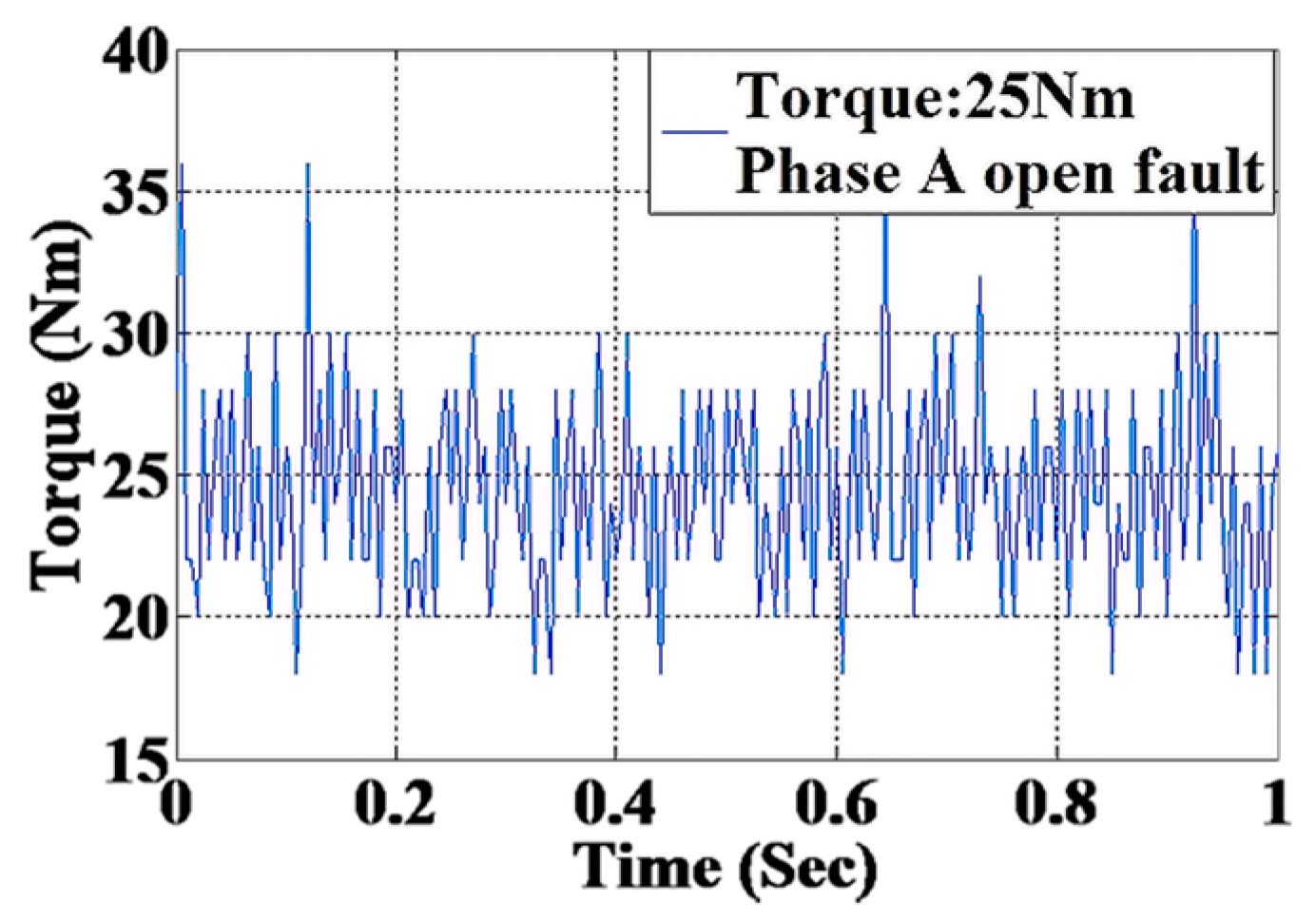
A short circuit was created between the terminals of phase A while the nine-phase SCIM was operating. The short-circuit current was interrupted by a 10 A quick-acting fuse. Figure 6a depicts phase A motor voltage during the short circuit, while Figure 6b shows the short circuit current during the fault. Figure 7 shows the shaft torque profile after the fault.
The measured torque in Figure 7 indicates that the short-circuit fault slightly drops the average torque by 4% compared with the healthy operation. On the other hand, the torque ripple has expanded by 42% in contrast to the healthy operation.

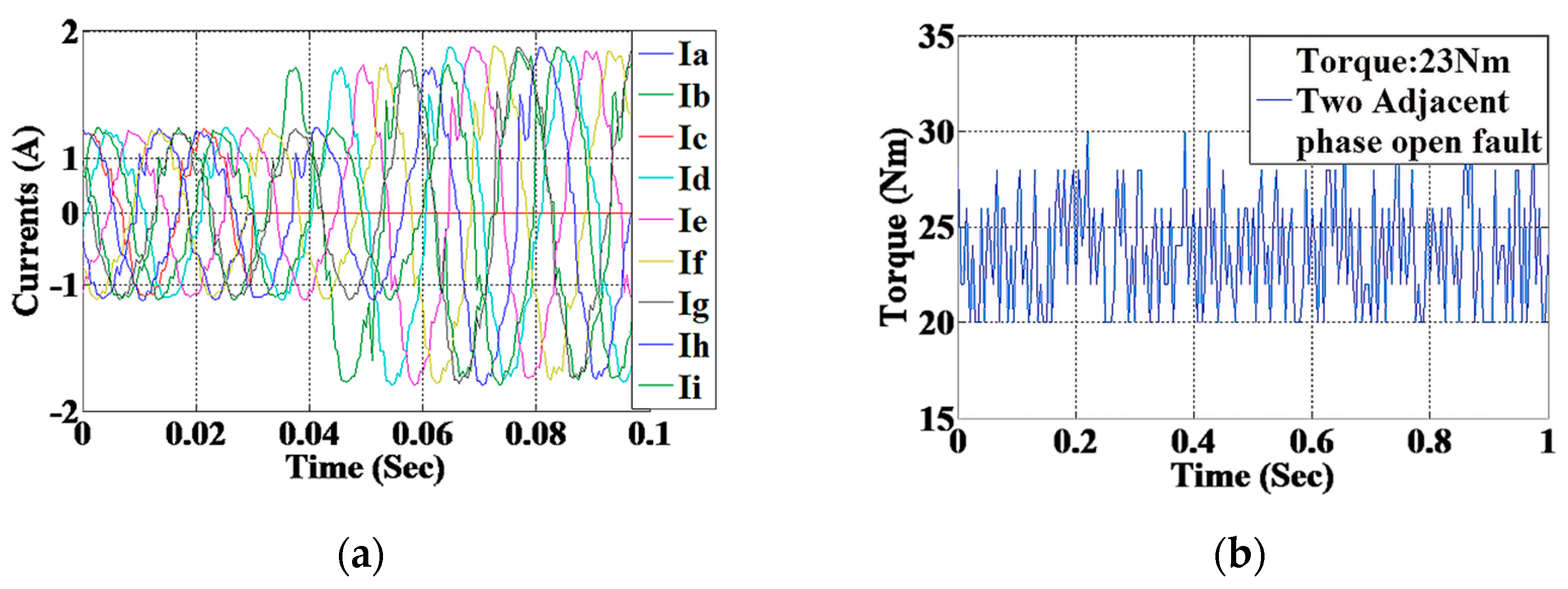
4.3. Operation with Two Adjacent Open-Phase Faults

In this setup, phases A and B were opened while the machine was running. Figure 8a shows the nine phases’ currents before and after the open-phase fault. The measured results in Figure 8a evidence that the current increase in the spare seven phases that are still in good shape after phase A and phase B were disconnected. From Figure 8a, it is clearly notable that the most affected currents are those that are time adjacent to one another, such as phase current Ic and phase current Ii. The torque profile of the SCIM operating with an open-phase defect is shown in Figure 8b. The motor continues to operate, but at a reduced average torque. The average torque has dropped by 22% compared with healthy operation and by 4% compared with operation with a short-circuit fault. On the other hand, the remaining seven phases improved the torque pulsation by 19% when contrasted with the healthy operation and by 57% when contrasted with the operation with a short-circuit fault. The reduction of torque ripple down to 43.47% when operating with an open-phase defect is caused by spatial magnetomotive harmonics generated by the seven-phase currents that have canceled or mitigated some of the spatial harmonics originating from the rotor currents. The seven-phase stator current produced phase-belt harmonics of order −6, +8, −13, +15…., while the rotor bar currents produced slot harmonics of order −13, +15, −27, 29.

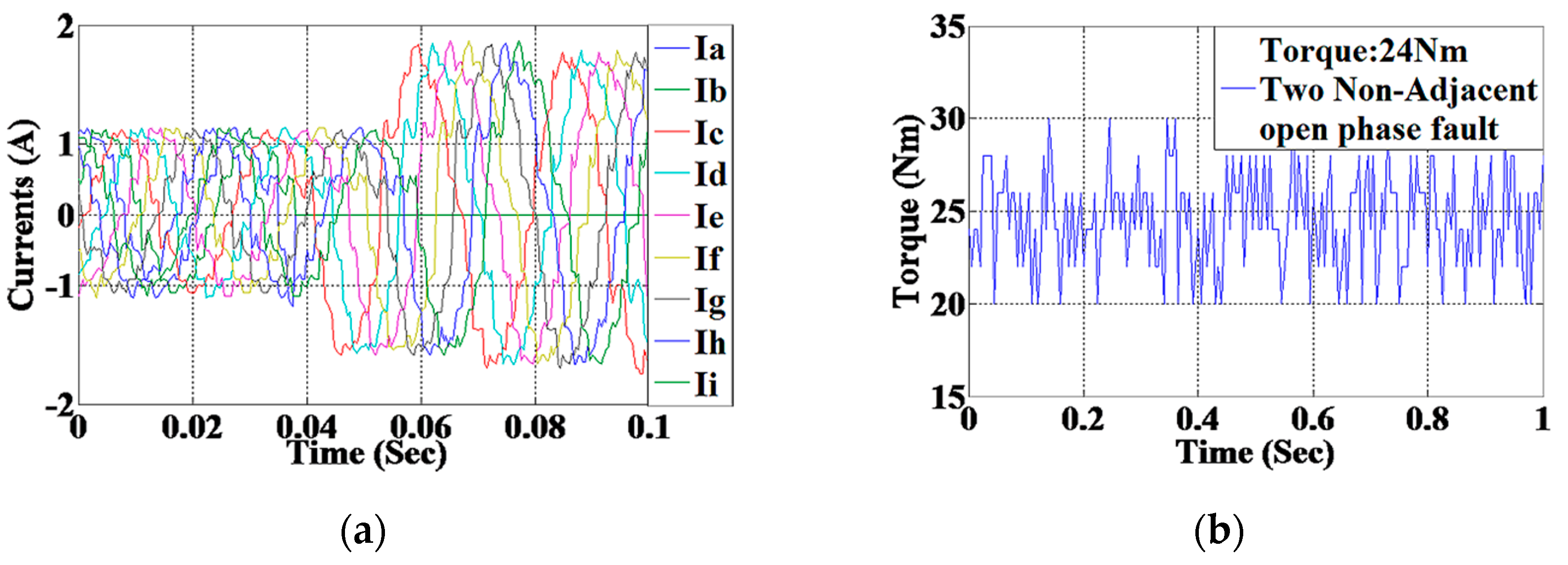
4.4. Operation with Two Non-Adjacent Open-Phase Faults

In this experimental setup, the non-neighboring phases A and C were also disconnected. Figure 9a shows the nine phases’ currents before and after the open-phase fault. It is notable from the measured results in Figure 9a that the current increased in the spare seven healthy phases after phases A and C were removed. From Figure 9a, it is notable that phase B is the most affected. The torque profile of the SCIM operating with an open-phase defect is shown in Figure 9b. Regarding the two-neighboring open-phase defects, the motor carries on operating but at reduced average torque. The average torque has dropped by 7.7% compared with healthy operation and by 4% compared with the operation with a short-circuit fault. Another observation is that the operation with two non-adjacent open-phase faults increases the average torque by 4% when compared with the operation with two adjacent open-phase faults. On the other hand, the remaining seven phases improved the torque pulsation by 23.7% when compared with the healthy operation, by 45.6% when compared with the operation with a short-circuit fault, and by 4.2% when compared with two non-adjacent open-phase fault operations.

5. Conclusions

This paper evaluates the fault tolerance ability of an inverter-fed nine-phase squirrel cage induction motor to operate under short-circuit and open-phase defects. The nine-phase inverter dive and induction motor were prototyped for experimental measurements. The latter evidenced that the nine-phase induction motor drive can carry on operating under faulty conditions but with reduced average torque. The torque ripple increased tremendously under short-circuit faults. Although the two-neighboring and non-neighboring open-phase defects slightly reduced the average torque, they operate with reduced torque ripple than the healthy nine-phase motor drive. The operation with two neighboring and non-neighboring open-phase faults makes the nine-phase motor operate as a seven-phase SCIM drive, exhibiting a good fault-tolerant capability. Future work will include the investigation of a control algorithm for the fault-tolerant nine-phase voltage source inverter that could mitigate the torque ripple contents when the squirrel cage induction motor is operating with open-phase faults.

Author Contributions

Conceptualization, M.M.; Methodology, M.G.M.; Validation, M.G.M.; Formal analysis, M.G.M. Investigation, M.G.M. and M.M.; Resources, M.M.; Data curation, M.G.M.; Writing—original draft, M.G.M.; Writing—review and editing, M.M.; Supervision, M.M. All authors have read and agreed to the published version of the manuscript.

Funding

This work was funded by the South African Research Foundation (NRF) through the Thuthuka research grant framework under the emerging career researcher and scholars’ tracks. Grant number: TTK190320423987—https://www.nrf.ac.za/ (accessed on 4 February 2020).

Institutional Review Board Statement

Not applicable.

Informed Consent Statement

Not applicable.

Data Availability Statement

Data available on request due to restrictions e.g., privacy or ethical. The data presented in this study are available on request from the corresponding author.

Conflicts of Interest

The authors declare no conflicts of interest.

References

  1. Arahal, M.R.; Duran, M.J.; Barrero, F.; Toral, S. Analysis of variable third harmonic injection for five-phase IM. In Proceedings of the European Control Conference (ECC), Budapest, Hungary, 23–26 August 2009; pp. 4350–4355. [Google Scholar]
  2. Bastos, R.R.; Valle, R.M.; Nau, S.L.; Filho, B.J.C. Modelling and analysis of a nine-phase induction motor with third harmonic current injection. In Proceedings of the 9th International Conference on Power Electronics and ECCE Asia (ICPE-ECCE Asia), Seoul, Republic of Korea, 1–5 June 2015; pp. 688–694. [Google Scholar]
  3. Zabaleta, M. Permanent Magnet Multi-Phase Machine Modeling and Control for Mv Wind Energy Applications. Doctoral Thesis, Liverpool John Moores University, Liverpool, UK, 2018. [Google Scholar]
  4. Jung, E.; Yoo, H.; Sul, S.-K.; Choi, H.-S.; Choi, Y.-Y. Nine-phase Permanent Magnet motor drive system for ultra-high-speed elevator. In Proceedings of the IEEE Energy Conversion Congress and Exposition, San Jose, CA, USA, 20–24 September 2009; pp. 1841–1846. [Google Scholar]
  5. Ertugrul, N.; Soong, W.; Dostal, G.; Saxon, D. Fault-tolerant motor drive system with redundancy for critical applications. In Proceedings of the IEEE Annual Power Electronics Specialists Conference, Cairns, QLD, Australia, 23–27 June 2002; Volume 3, pp. 1457–1462. [Google Scholar]
  6. Wang, S.; Zhang, X.; Xiong, G.; Wang, J.; Zhang, Z.; Wang, X. A Half-bridge Strategy Based Fault-tolerant Control for BLDCM under Open Circuit Fault. In Proceedings of the 15th IEEE Conference on Industrial Electronics and Applications (ICIEA), Kristiansand, Norway, 9–13 November 2020; pp. 1750–1755. [Google Scholar]
  7. Vasile, I.; Tudor, E.; Popescu, M.; Dumitru, C.; Popovici, L.; Sburlan, I.C. Electric Drives with Multi-phase Motors as a Better Solution for Traction Systems. In Proceedings of the 11th International Symposium on Advanced Topics in Electrical Engineering (ATEE), Bucharest, Romania, 28–30 March 2019; pp. 1–5. [Google Scholar]
  8. Yang, S.; Bryant, A.T.; Mawby, P.; Xiang, D.; Ran, L.; Tavner, P.J. An Industry-Based Survey of Reliability in Power Electronic Converters. IEEE Trans. Ind. Appl. 2011, 47, 1441–1451. [Google Scholar] [CrossRef]
  9. Liao, X.; Shen, Q.; Hu, Y.; Yang, C.; Chen, X.; Li, H. Fault protection for a SiC MOSFET based on gate voltage subjected to short circuit type II. Microelectron. Reliab. 2020, 107, 113624. [Google Scholar] [CrossRef]
  10. Thomson, W.T.; Fenger, M. Current signature analysis to detect induction motor faults. IEEE Ind. Appl. Mag. 2001, 7, 26–34. [Google Scholar] [CrossRef]
  11. Duran, M.J.; Barrero, F. Recent Advances in the Design, Modeling, and Control of Multi-phase Machines—Part II. IEEE Trans. Ind. Electron. 2016, 63, 459–468. [Google Scholar] [CrossRef]
  12. Ruba, M.; Fodorean, D. Analysis of Fault-Tolerant Multiphase Power Converter for a Nine-Phase Permanent Magnet Synchronous Machine. IEEE Tran. Ind. Appl. 2012, 48, 2092–2101. [Google Scholar] [CrossRef]
  13. Pan, Z.; Ikaheimo, J. Nine-phase variable speed drive system with reduced switching PWM. In Proceedings of the 2014 International Conference on Electrical Machines (ICEM), Berlin, Germany, 2–5 September 2014; pp. 823–828. [Google Scholar]
  14. Kumar, D.; Davari, P.; Zare, F.; Blaabjerg, F. Analysis of three-phase rectifier systems with controlled DC-link current under unbalanced grids. In Proceedings of the IEEE Applied Power Electronics Conference and Exposition (APEC), Tampa, FL, USA, 26–30 March 2017; pp. 2179–2186. [Google Scholar]
  15. Guzman, H.; Barrero, F.; Duran, M.J. IGBT-gating failure effect on a fault-tolerant predictive current-controlled five-phase induction motor drive. IEEE Tran. Ind. Electron. 2015, 62, 15–20. [Google Scholar] [CrossRef]
  16. De Souza, T.S.; Bastos, R.R.; Filho, B.J.C. Modeling and Control of a Nine-Phase Induction Machine With Open Phases. IEEE Trans. Ind. Appl. 2018, 54, 6576–6585. [Google Scholar] [CrossRef]
  17. Pan, Z.; Ikaheimo, J. Control optimization of nine-phase variable speed drive. In Proceedings of the IEEE International Electric Machines and Drives Conference (IEMDC), Coeur d’Alene, ID, USA, 10–13 May 2015; pp. 910–915. [Google Scholar]
  18. Ajaz, M.; Anwar, A.B.; Tanwar, A.K.; Vashisht, B. Simulation, and mathematical modeling of nine-phase Induction Motor Drive. In Proceedings of the 12th IEEE International Conference Electronics, Energy, Environment, Communication, Computer, Control (INDICON), New Delhi, India, 17–20 December 2015; pp. 1–6. [Google Scholar]
  19. Jaya, A.; Soebagio, S.; Purnomo, M.H. Nine-phase induction motor dynamic model based on 3 × 9 transformation matrix. Telkomnika 2013, 11, 265–276. [Google Scholar] [CrossRef]
  20. De Souza, T.S.; Bastos, R.R.; Filho, B.J.C. Fault analysis in an inverter-Fed Nine-Phase induction machine. In Proceedings of the IEEE Energy Conversion Congress and Exposition (ECCE), Cincinnati, OH, USA, 1–5 October 2017; pp. 371–378. [Google Scholar]
  21. Ruba, M.; Surdu, F.; Szabo, L. Study of a Nine-Phase Fault-Tolerant Permanent Magnet Starter-Alternator. J. Comput. Sci. Control. Syst. 2011, 4, 149–154. [Google Scholar]
  22. Onsal, M.; Demir, Y.; Aydin, M. A New Nine-Phase Permanent Magnet Synchronous Motor with Consequent Pole Rotor for High-Power Traction Applications. IEEE Trans. Magnet. 2017, 53, 2–7. [Google Scholar] [CrossRef]
  23. Sowmiya, M.; Renukadevi, G.; Rajambal, K. IFOC of a Nine Phase Induction Motor Drive. Int. J. Eng. Sc. Innov. Tech. 2013, 2, 72–78. [Google Scholar]
  24. Sui, Y.; Liu, J.; Yin, Z.; Zheng, P.; Cheng, L.; Tang, D. Short-circuit fault detection for a five-phase 30-slot/32-pole permanent-magnet synchronous machine. In Proceedings of the 21st International Conference on Electrical Machines and Systems (ICEMS), Jeju, Republic of Korea, 7–10 October 2018; pp. 50–54. [Google Scholar]
  25. Pavithran, K.N.; Parimelalagan, R.; Krishnamurthy, M.R. Studies on inverter-fed five-phase induction motor drive. IEEE Trans. Ind. Appl. 1988, 3, 224–235. [Google Scholar] [CrossRef]
  26. Kong, W.; Qu, R.; Huang, J.; Kang, M. Air-gap and yoke flux density optimization for multi-phase induction motor based on novel harmonic current injection method. In Proceedings of the 2016 XXII International Conference on Electrical Machines (ICEM), Lausanne, Switzerland, 4–7 September 2016; pp. 100–106. [Google Scholar]
  27. Rockhill, A.A.; Lipo, T.A. A generalized transformation methodology for polyphase electric machines and networks. In Proceedings of the IEEE International Electric Machines & Drives Conference (IEMDC), Coeur d’Alene, ID, USA, 10–13 May 2015; pp. 27–34. [Google Scholar]
  28. Komurgoz, G.; Geitner, G. Application of the unified electric motor Bond Graph model to HB-type and PM-type Vernier machines. In Proceedings of the 42nd Annual Conference of the IEEE Industrial Electronics Society (IECON), Florence, Italy, 23–26 October 2016; pp. 4263–4268. [Google Scholar]
  29. Ashourloo, M.; Trescases, O. Short-Circuit Fault Diagnosis and Post-Fault Control with Adaptive PLL-Based Synchronization for a Multi-phase Quasi-Square-Wave DC-DC Converter. In Proceedings of the 20th European Conference on Power Electronics and Applications (EPE’18 ECCE Europe), Riga, Latvia, 17–21 September 2018; pp. 1–10. [Google Scholar]
  30. Boldea, I.; Nasar, S.A. The Induction Machine Handbook; CRC Press: New York, NY, USA, 2002. [Google Scholar]
  31. Lojek, B. William Schockley: The Will to Think; Springer: Cham, Switzerland, 2022. [Google Scholar]
  32. Holmes, G.; Lipo, T.A. Frontmatter in Pulse Width Modulation for Power Converters: Principles and Practice; Willey-IEEE Press: Hoboken, NJ, USA, 2003. [Google Scholar]
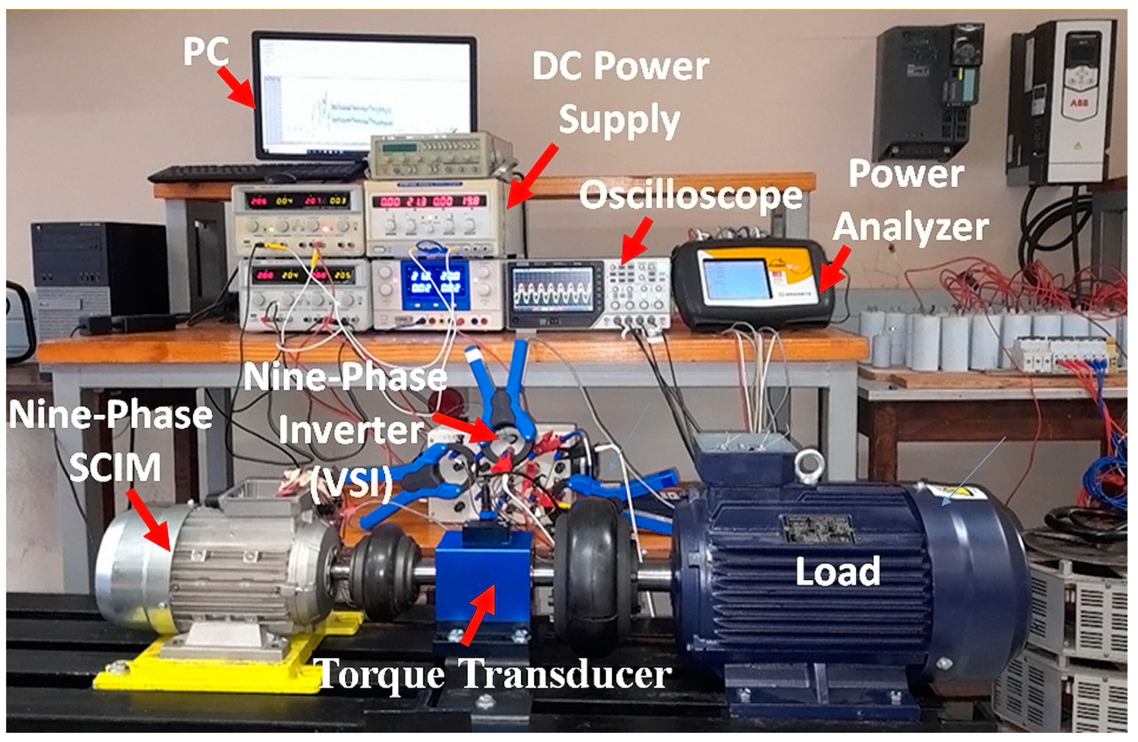
Figure 1. Experimental laboratory setup.
Engproc 60 00014 g001
Figure 2. Investigated induction motor: (a) squirrel cage rotor and (b) nine-phase stator.
Engproc 60 00014 g002
Figure 3. Nine-phase inverter drive and its different components.
Engproc 60 00014 g003
Figure 4. Measured nine-phase motor voltages and currents under healthy operation: (a) phase voltages and (b) line currents.
Engproc 60 00014 g004
Figure 5. Measured shaft torque under healthy operation: average torque of 26 Nm and torque ripple of 53.84%.
Engproc 60 00014 g005
Figure 6. Measured phase A voltage and current under short-circuit fault: (a) phase voltage and (b) line current.
Engproc 60 00014 g006
Figure 7. Measured torque under phase A short-circuit fault: average torque of 25 Nm and torque ripple of 76.58%.
Engproc 60 00014 g007
Figure 8. Measured current and torque under two adjacent open-phase faults: (a) transient currents and (b) shaft torque: average torque of 23 Nm and torque ripple of 43.47%.
Engproc 60 00014 g008
Figure 9. Measured current and torque under two non-adjacent open-phase faults: (a) transient currents and (b) shaft torque: average torque of 24 Nm and torque ripple of 41.67%.
Engproc 60 00014 g009
Table 1. Specifications, parameters, and ratings.
DescriptionValuesUnit
Rated line current1.59A
Base frequency of the motor50Hz
Nominal line voltage 150V
Number of phases 9-
Rated speed 1460rpm
Number of pole pairs2-
PWM switching frequency4kHz
Rated DC bus voltage 230V
Stator leakage reactance per phase0.567
Rotor leakage reactance per phase 0.224
Stator resistance per phase 2.805
Rotor resistance referred to the stator2.3
Number of stator slots36-
Number of rotor bars28-
Number of series conductors per phase192-
Outer radius68mm
Inner radius39.85mm
Core length: stator and rotor160mm
Shaft radius10mm
Length of airgap0.35mm
Disclaimer/Publisher’s Note: The statements, opinions and data contained in all publications are solely those of the individual author(s) and contributor(s) and not of MDPI and/or the editor(s). MDPI and/or the editor(s) disclaim responsibility for any injury to people or property resulting from any ideas, methods, instructions or products referred to in the content.