Abstract
Automotive safety encompasses various measures, including seat belts, airbags, and advanced driver assistance systems, to minimise the risk of accidents and protect vehicle occupants. Seat belts play a crucial role in restraining occupants during collisions, reducing the likelihood of serious injuries. A part of a vehicle’s seat belt system is commonly referred to as a “retractor spindle”. The seat belt webbing’s movement and tension are managed by the seat belt retractor spindle. The selection of spindle material is crucial for seat belt retraction and extraction, with aluminium alloy being favoured due to its light weight and high strength, ensuring efficient and reliable performance in automotive safety systems. In this regard, an attempt was made to create a simulation material model for , which in turn led to a spindle break load simulation. For a specimen and a spindle made of the same material, experimental and finite element analyses were conducted. Specimen-level tests were carried out, and behaviour was studied using the MAT_ADD_EROSION damage model and the MAT_PLASTICITY_COMPRESSION_TENSION material model in LS-Dyna. The obtained ultimate strain value was used create the material card. Spindle analysis was carried out with the same control cards and material cards. From the experimental tests and finite element analysis, we conclude that the proposed simulation material model for predicts the spindle breaking load and failure modes to acceptable levels.
1. Introduction
Automotive safety is of utmost importance as it aims to protect vehicle occupants and other road users from the risk of accidents and minimise the severity of injuries in the event of a collision. It involves a combination of design, technology, and user behaviour to create a safer driving environment. One of the most significant aspects of automotive safety is the proper use of seat belts. One of the main causes of severe injuries and fatalities in auto accidents, ejection from the vehicle, is significantly decreased when seat belts are worn correctly. This lowers the chance of injury to delicate body parts and important organs.
A retractor spindle, as shown in Figure 1, is typically a component of a seat belt system in a vehicle. It is responsible for controlling the movement and tension of the seat belt webbing. Inside the retractor mechanism, there is a spring-loaded spindle, around which, the seat belt webbing is wound. When the seat belt is pulled out, the spindle rotates, allowing the webbing to extend. The retractor spindle is designed to lock and hold the webbing in place during sudden stops or collisions, preventing the occupants from being thrown forward. The retractor spindle usually incorporates a locking mechanism that engages when the vehicle experiences rapid deceleration. This locking mechanism can also be activated by pulling the seat belt out quickly or at a certain angle. Once engaged, the retractor spindle prevents the webbing from being further extended, keeping the occupant secure in their seat.
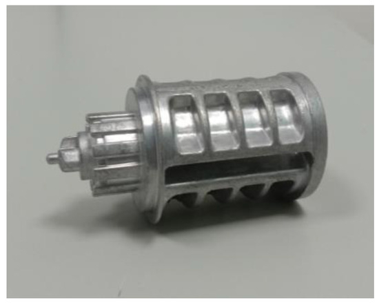
Figure 1.
Retractor spindle.
The retraction and locking element are both located inside the rigid frame construction of the seat belt retractor. Because of the crash force operating on the frame, a spindle is attached to it and is allowed to rotate in a controlled manner, ensuring that the frame does not deform. The retractor is an assembly of several parts consisting of a spindle, tie bar, pretensioner, brackets, etc. The spindle of the retractor is made up of a light material such as aluminium alloy, in order to reduce the weight of the retractor. The spindle plays a major role in a seat belt. When the wound webbing is pulled, the spindle will release webbing by rotating around the spindle. The spindle will begin to experience the most force after all the webbing has been released from it. Therefore, spindle should be strong enough to withstand the webbing load.
The objectives of this study were to comprehensively assess the mechanical behaviour and performance of two different components of a specimen and a spindle through a combination of experimental testing and computational analysis using the finite element analysis (FEA) method. The method focuses on an iterative finite element method technique with the aim of predicting fracture behaviour while taking failure into account [1,2,3]. Experimental tests were conducted on the specimen under various loading conditions to obtain the ultimate strain and non-linear behaviour of the material. A detailed 3D model of the specimen using computer aided design (CAD) software CATIA V5 which captured its geometric features was created and analysed. The behaviour of the metal aluminium alloy was examined by combining experiments and simulations [4].
2. Material Details
The material used in this project was the aluminium alloy with a density of 2.7 g/cm3. Aluminium alloys are used to produce components with high strength and high dynamic load ability, which are predestined for use in areas such as aerospace and automotive industries [5,6,7,8,9]. The material used in the present study had a composition of 90% of aluminium, 3% copper and 7% silicon. The die casting method was used to prepare the product. The main reason for choosing to use aluminium alloy for the spindle was because it has low weight and high strength.
The test results were compared against relevant standards, such as ASTM (American Society for Testing and Materials) or ISO (International Organization for Standardization) standards. Compliance with these standards indicated that the material met the required quality and performance levels. The behaviour of high-purity aluminium and diluted aluminium alloys regarding elastic and plastic deformation was reviewed [10]. A validation report was prepared, summarising the testing methods, results, and conclusions. It provided evidence that the material was validated and met the specified requirements. Material validation is an ongoing process, particularly for critical applications.
Methodology
Two different tests were conducted on the material, as shown in Figure 2. Initially, a specimen-level test was conducted, and a component-level test was conducted by using the same material and damage card. The objectives were to use a mix of computational analysis by utilising the finite element analysis (FEA) method and experimental testing to thoroughly evaluate the mechanical behaviour and performance of two different components of a specimen and a spindle [11,12,13,14]. To forecast fracture behaviour while taking failure into consideration, the method focused on an iterative finite element method technique. The specimen underwent experimental tests under various loading scenarios to determine the material’s non-linear behaviour and ultimate strain. Using computer-aided design (CAD) software, a precise 3D model of the specimen was constructed, which was then evaluated to capture its geometric properties [15,16,17,18]. Combining simulations and experiments allowed the researchers to analyse the behaviour of the metal aluminium alloy.
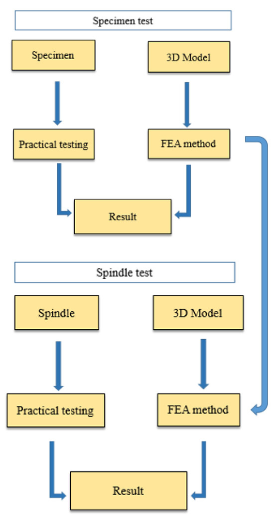
Figure 2.
Methodology.
3. Testing on Specimen and Component
3.1. Experiments on Specimen
ASTM standards were used for the experimental test. The types of mechanical tests conducted on the specimen were uniaxial tension tests, tension groove tests, tensile tests on cylindrical specimens, shear tests, bend of bar tests, and compression tests. A specimen-level test was conducted to obtain stress vs. stain curves and force vs. displacement curves.
3.2. Finite Element Analysis on Specimen
Finite element analysis (FEA) is a numerical method used to analyse the behaviour of structures and components by dividing them into finite elements. When applied to a specimen, FEA can provide insights into its mechanical behaviour, stress distribution, deformation, and other relevant characteristics. FEA was performed on the same specimen by creating a CAD model. Hypermesh was used to create a CAD model of the ASTM standard specimen. The model was created in Hypermesh using the nodes and line command. The analysis was performed using the LS-Dyna solver.
3.3. Experimental Test on Spindle
In the experimental test, a real product was tested under several loading conditions. The types of tests conducted on the spindle were uniaxial tension, shear, bending of bar, and compression tests. In the experimental test, the same material was used as that used for the specimen-level test. The spindle was created using the die casting method. An aluminium alloy (AlSi9Cu3) material was used for the spindle. Aluminium has low density and high strength and hardness. There were four types of experimental tests conducted on the spindle. They were uniaxial tension, shear, three-point bending, and compression tests.
3.4. Finite Element Analysis on Spindle
Finite element analysis (FEA) can be a useful tool for analysing the structural behaviour and performance of a retractor spindle. CATIA CAD software was used to create the spindle’s CAD model. The CAD model was made to match the tested spindle exactly. The CAD model was imported to Hypermesh-2020 software to create mesh on the spindle. In addition, the spindle fixture was created and meshed on it. Using tetrahedral elements to mesh the retractor spindle in LS-DYNA is a valid approach when dealing with complex geometries. Tetrahedral elements are suitable for representing irregular shapes and intricate structures, allowing for a more accurate representation of the geometry.
When meshing with tetrahedral elements, the refinement of critical areas with high stress or deformation must be focussed on, including stress concentration zones and structural details. A well-connected mesh without gaps or overlaps must be ensured by using appropriate techniques. Tetrahedral elements are effective for complex structures like the retractor spindle in Hypermesh, providing accuracy in geometry representation and deformation patterns, but meticulous refinement, aspect ratio control, and connectivity are essential for reliable simulations. The same material card was created for the spindle using the LS-Dyna solver because the material was identical to that utilised for the specimen-level test. The boundary condition was created based on the type of loading.
4. Results and Discussion
4.1. Specimen-Level Test
In the specimen-level test, the specimen was tested in various loading conditions. Here, FEA was used to gain responses from a different-shaped specimen. The main aim of the FEA was to find the breaking point in a different situation to tally with the experimental test. A new material card and damage card were created to predict the damage.
- i.
- Uniaxial tension
Testing a sample with a single force until it breaks is known as uniaxial testing, as shown in Figure 3. In these tests, the force delivered to the specimen was calculated as a function of the separation between the grips of the testing apparatus. Specimen failure occurred when the force value approached its maximum. Maximum stress was reached by the specimen, at which point, necking began, and failure occurred. After the specimen graph failed in the FEA approach, it decreased to zero.
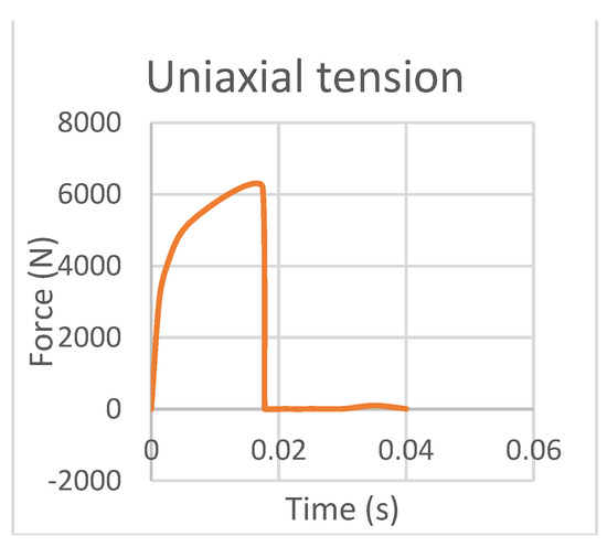
Figure 3.
Uniaxial tension.
- ii.
- Tension grooves
The tension groove specimen consisted of a small groove in the tensile specimen. When force was applied on the specimen, stress developed at the grooved area. The stress was concentrated at the critical region, which, upon further loading, developed internal cracking and sudden failure at maximum loading. The force time graph in the above graph failed after reaching its maximum value, as shown in Figure 4.
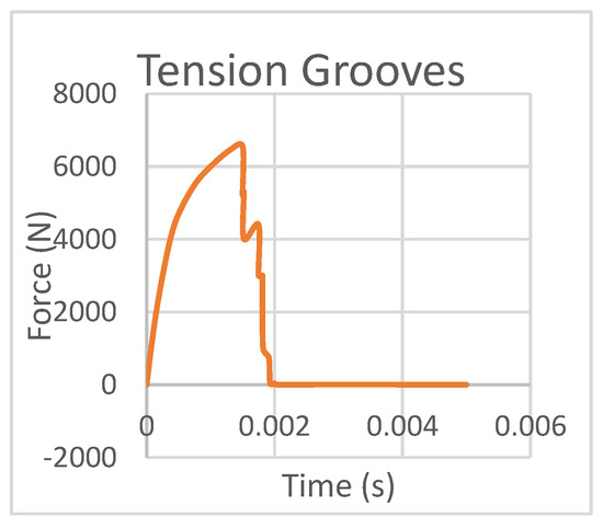
Figure 4.
Tension Grooves.
- iii.
- Tension on cylindrical specimen
The tension test was performed using the cylindrical specimen model in LS–dyna. The model was cylindrical in shape, and the cross section at the middle of the specimen was different than either side of the specimen. Minimum force was required to break the specimen because of the area in the middle of the specimen.
When force was increased gradually, the lesser cross section area started to deform. Due to the smaller cross section, the specimen failed with a minimum load. Figure 5 shows force versus time; there was a sudden drop after the failure of the specimen.
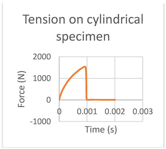
Figure 5.
Tension on cylindrical specimen.
- iv.
- Shear
Here, the specimen was fixed with two side faces. The shear specimen had an angled cut section, which enabled us to obtain the shear stress at the critical region. The force was applied equally and oppositely at the side faces. Initially, the specimen behaved elastically under the linear condition; then, plastic deformation began. The critical region began to fail, and this resulted in the complete breakdown of the specimen. The test results have been plotted in Figure 6.
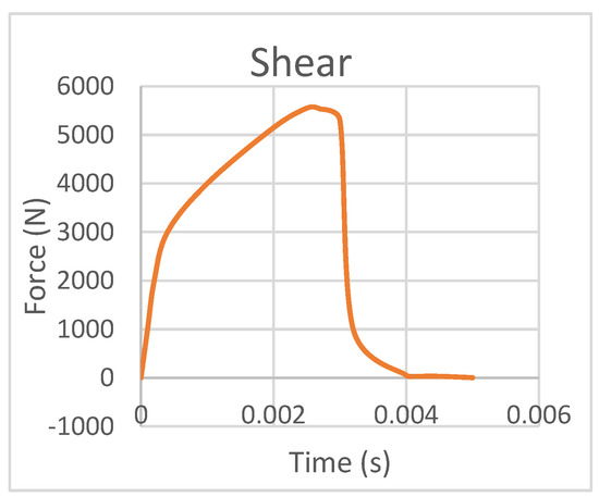
Figure 6.
Shear test result.
- v.
- Bending of bar
The three-point bending test was performed for the bar specimen, and a graph is shown in Figure 7.
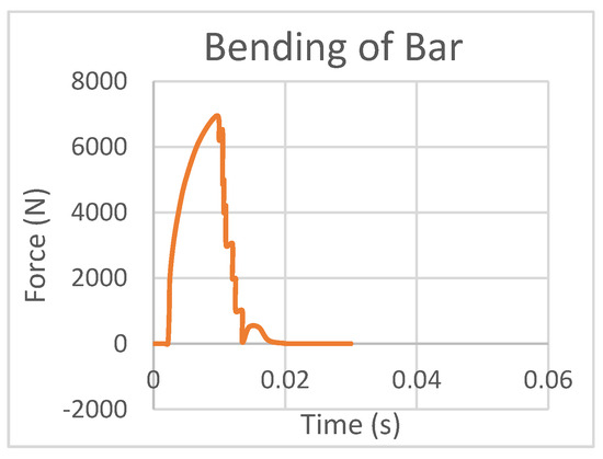
Figure 7.
Bending of bar.
- vi.
- Compression
The compression test was carried out experimentally and analysed using the FEA method and the results have been plotted in Figure 8. Force was applied on the specimen from one end and the other side of the specimen was constrained. For the compression test, more force was required to compress the specimen. As we can see in the above graph, there was no drop in the graph because in the compression loading specimen, the volume decreased and atoms become very tightly packed, and for this reason, more force was required to compress the specimen, and we observed no failure.
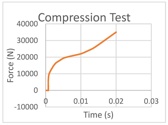
Figure 8.
Compression test result.
- vii.
- True stress verses true strain curve
Figure 9 above shows the true stress strain curve for the material. It uses the instantaneous or actual area of the specimen at any given point, as opposed to the original area used in the engineering value. Two curves were defined in the output. The simulation gave two different curves for tension and compression. A indicates the load id curve of compression, and B indicates the load id curve of tension.
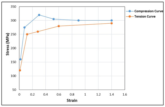
Figure 9.
True stress strain.
4.2. Component Level Test
In the component-level test, the spindle was tested under various loading conditions, as in the specimen level test. Here, FEA was used to obtain a response from the spindle. Finding the breaking point in various situations to match experimental testing is the primary goal of finite element analysis. We used the same damage and material cards to predict the damage. After preparing the deck set up for the spindle, certain loading conditions were applied. To match the experimental data, the spindle was loaded using the webbing in finite element analysis.
- i.
- Uniaxial tension test
LS-dyna-R7.1.2 software was used to perform a spindle-based uniaxial tension test and the results are shown in Figure 10. The spindle was created using the CAD software. For the spindle, tetrahedral mesh was produced. Here, the spindle was partially fixed with two supports. Webbing was pulled from the end that was parallel to the axis of the spindle.
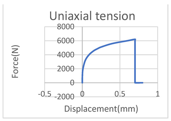
Figure 10.
Uniaxial test on spindle.
- ii.
- Shear test
The shear test was conducted on the spindle using the FEA method, and like in the experimental test, the spindle was constrained from one end and rotated along the axis of the spindle. Figure 11 represents the displacement of the spindle when force was applied and the relaxation time. When the force was applied to the spindle by pulling the webbing, it began to twist, and when force was released from the maximum limit, the spindle tried to move back to its original shape. But the spindle did not return to its original position fully, and there was displacement from its initial position.
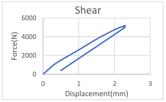
Figure 11.
Shear test on spindle.
- iii.
- Three-point bending
The three-point bending test was conducted on the spindle experimentally, using the same loading condition method used when the spindle was analysed using the finite element method. Here, the webbing was pulled vertically upward. When all webbing was released, the spindle experienced the maximum force. From Figure 12, when the load gradually increased, there was a small level of deflection, and when the load was released, the spindle tried to return to its original shape. Unfortunately, the spindle remained slightly deflected from its original shape.
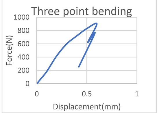
Figure 12.
Three-point bending of specimen.
- iv.
- Compression test
FEA was used with the spindle to determine the behaviour of the material during the compression loading. The spindle was fixed at one end. Using the load constraint, elements on one edge were fixed. The compression is a form of axial loading. When the compression load acted on the spindle, the volume of the spindle changed. From Figure 13, the force analysis showed that more force was required to compress the spindle. The maximum force caused a small level of displacement.
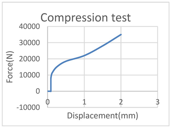
Figure 13.
Compression test on spindle.
- v.
- Sectional force
The spindle was simulated using the LS-Dyan software. The spindle was connected to two supports which allowed the spindle to rotate within its axes. Webbing was wound over the spindle. A section of the spindle was taken for the analysis. When the webbing was pulled at a certain force, the spindle began to rotate, and when the spindle experienced maximum stress by pulling, the region of the spindle where webbing was fixed started to develop cracks, and at a certain point, it broke. Here, the section force is plotted. Figure 14 plots the section force versus time, where we can find the maximum force developed in the section.
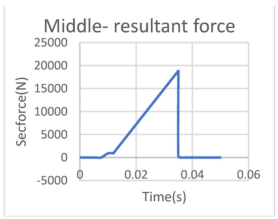
Figure 14.
Sectional force of spindle.
- vi.
- Element regularisation
Element regularisation in LS-DYNA is a technique used to improve the quality of finite element meshes, especially when dealing with irregular or distorted elements. Regularisation helps correct mesh irregularities and improve the accuracy of the analysis results. In LS-DYNA, there are several options available for element regularisation, including the use of the *ELEMENT_REGULARIZATION keyword. This keyword allows one to specify various parameters and settings to control the regularisation process.
The spindle was initially tested with a 0.5 mm element size, and a 0.5 mm global element size was maintained during spindle meshing. Tetrahedral mesh is the kind of mesh that was produced. The section force versus time of a spindle with a global size of 0.5 mm is depicted in the above graph. This simulation revealed that the spindle would fail by 15 kN.
By maintaining a consistent global size of 1 mm and using tetrahedral elements for meshing, it was possible to accurately capture the behaviour of the spindle under a load. The fact that the spindle failed at a higher load of 20 kN indicates increased strength compared to the results obtained from the 0.5 mm mesh.
Plotting the section force and time graph allows for a better understanding of the spindle’s response to the applied load. It provides insights into the stress distribution and deformation patterns, helping us to evaluate the structural integrity and failure modes of the spindle. Comparing the results of different mesh sizes, as shown in Figure 15, Figure 16 and Figure 17, is essential for validation and optimisation. The fact that the 1 mm mesh resulted in a higher failure load suggests that it is a more reliable representation of the spindle’s behaviour.
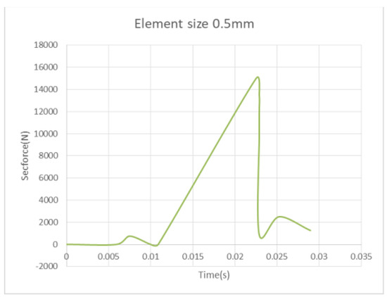
Figure 15.
Element size of 0.5 mm.
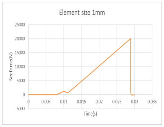
Figure 16.
Element size of 1 mm.
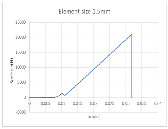
Figure 17.
Element size of 1.5 mm.
Similarly, for the same 1.5 mm spindle, mesh was generated and simulated. When 1.5 mm was maintained as the global size, the spindle was meshed with a tetrahedral element. The same procedure was applied to the 1.5 mm spindle. A section force and time graph is plotted. Here, it was shown that the spindle would fail at 21.5 kN, and considering all three element size results, output failure force was compared. The 1.5 mm mesh size resulted in a failure load of 21.5 kN for the spindle. This indicates a slightly higher failure load compared to both the 0.5 mm and 1 mm mesh sizes. By maintaining a consistent global size of 1.5 mm and using tetrahedral elements for meshing, we continued to capture the behaviour of the spindle accurately. The higher failure load suggests even stronger behaviour for the spindle compared to the 1 mm and 0.5 mm mesh sizes. Comparing the failure loads across all three mesh sizes allowed us to evaluate the sensitivity of the results to the mesh size. It appears that as the mesh size increased from 0.5 mm to 1 mm and then to 1.5 mm, the failure load gradually increased. This trend suggests that the larger element size was able to capture the behaviour of the spindle more accurately, resulting in higher failure loads.
- vii.
- Triaxiality curve
The triaxiality curve is a graphical representation in Figure 18 which shows the relationship between stress triaxiality and material behaviour during deformation. This enabled us to understand the response of materials under complex loading conditions. Stress triaxiality is a measure of the distribution of stress components in a material. It is defined as the ratio of the hydrostatic stress (average stress) to the equivalent Von Mises Stress (shear stress). The triaxiality value can range from −1 to 1, representing different stress states.
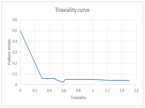
Figure 18.
Triaxiality curve.
These findings provide a firm basis for estimating the biodegradability of bio-based composites over time. Further investigation of the interactions of MMT nanoclay with the epoxy matrix and biodegradation microorganisms could lead to the creation of even more sustainable and effective bio-based composites.
5. Conclusions
The MAT_124 material type was used to carry out material validation for the spindle material of an aluminium cast product. Aluminium alloy cast product specimens underwent testing at the specimen level under various loading conditions, and the same specimen was then simulated using LS-dyna by using the MAT_124 material type. After studying the results of the specimen-level test that analysed material behaviour and ability, we could draw the conclusion that the same material card can be utilised for component-level testing. After conducting the experimental test and finite element analysis on the spindle, we concluded that the developed simulation material model for predicts the spindle breaking load and failure modes to satisfactory levels. The material model failure approach, by employing MAT_124 in addition to the MAT_ADD_EROSION Generalized Incremental Stress-State Dependent Damage Model (GISSMO), accurately predicted realistic material behaviour in both the specimen- and component-level simulations. Aluminium alloy had a lower weight compared to the existing material. The required responses were obtained from the new material; therefore, the aluminium alloy ) material can used as spindle material.
Author Contributions
Conceptualization, N.C. and S.P.; methodology, N.C. and S.P.; software, S.; validation, N.C. and S.P. and S.; formal analysis, R.P.S.; investigation, S..; resources, N.C. and S.P.; data curation, S.; writing—original draft preparation, N.K. and D.K.; writing—review and editing, N.K. and D.K.; visualization, R.P.S.; supervision, N.K.; project administration, N.C. All authors have read and agreed to the published version of the manuscript.
Funding
This research received no external funding.
Institutional Review Board Statement
Not applicable.
Informed Consent Statement
Not applicable.
Data Availability Statement
The data are part of an ongoing study and hence cannot be shared.
Conflicts of Interest
The following Authors Somanagouda Patil and Naveen Chandra are employed by the company Autoliv. The remaining authors declare that the research was conducted in the absence of any commercial or financial relationships that could be construed as a potential conflict of interest.
References
- Xiao, Y.; Hu, Y. An Extended Iterative Identification Method for the GISSMO Model. Metals 2019, 9, 568. [Google Scholar] [CrossRef]
- Chen, X.; Chen, G.; Huang, L. Calibration of GISSMO model for fracture prediction of a super high formable advanced high strength steel. In Proceedings of the 15th International LS-Dyna Users Conference, Metal Forming, Dearborn, MI, USA, 10–12 June 2018. [Google Scholar]
- Effelsberg, J.; Haufe, A.; Feucht, M.; Neukamm, F.; Du Bois, P. On parameter identification for the GISSMO damage model. In Proceedings of the 12th International LS-DYNA® Users Conference, Dearborn, MI, USA, 3–5 June 2012. [Google Scholar]
- Hu, Y.; Xiao, Y.; Jin, X.; Zheng, H.; Zhou, Y.; Shao, J. Experiments and FEM simulations of fracture behaviors for ADC12 aluminum alloy under impact load. Met. Mater. Int. 2016, 22, 1015–1025. [Google Scholar] [CrossRef]
- Driemeier, L.; Brünig, M.; Micheli, G.B.; Alves, M. Experiments on stress-triaxiality dependence of material behaviour of aluminium alloys. Mech. Mater. 2010, 42, 207–217. [Google Scholar] [CrossRef]
- Zhang, Z.; Cui, Y.; Yu, G. Damaged and failure characterization of 7075-T6 Al alloy based on GISSMO model. J. Mech. Sci. Technol. 2021, 35, 1209–1214. [Google Scholar] [CrossRef]
- Ramnath, B.V.; Elanchezhian, C.; Chandrasekhar, V.; Kumar, A.; Asif, S.M.; Mohamed, G.R.; Raj, D.V.; Kumar, C.S. Analysis and Optimization of Gating System for Commutator End Bracket. Procedia Mater. Sci. 2014, 6, 1312–1328. [Google Scholar] [CrossRef][Green Version]
- Chen, Y.; Clausen, A.H.; Hopperstad, O.S.; Langseth, M. Stress–strain behaviour of aluminium alloys at a wide range of strain rates. Int. J. Solids Struct. 2009, 46, 3825–3835. [Google Scholar] [CrossRef]
- Narasayya, C.; Rambabu, P.; Mohan, M.; Mitra, R.; Prasad, N.E. Tensile deformation and fracture behaviour of an aerospace aluminium alloy AA2219 in different ageing conditions. Procedia Mater. Sci. 2014, 6, 322–330. [Google Scholar] [CrossRef]
- Reed, R.P. Aluminium 2. A review of deformation properties of high purity aluminium and dilute aluminium alloys. Cryogenics 1972, 12, 259–291. [Google Scholar] [CrossRef]
- Achani, D.; Lademo, O.; Engler, O.; Hopperstad, O.S. Evaluation of constitutive models for textured aluminium alloys using plane-strain tension and shear tests. Int. J. Mater. Form. 2011, 4, 227–241. [Google Scholar] [CrossRef][Green Version]
- Allahverdizadeh, N.; Gilioli, A.; Manes, A.; Giglio, M. An experimental and numerical study for the damage characterization of a Ti–6AL–4V titanium alloy. Int. J. Mech. Sci. 2015, 93, 32–47. [Google Scholar] [CrossRef]
- Kumar, S.; Pandouria, A.K.; Chakraborty, P.; Tiwari, V. Evaluation of Johnson-Cook failure model for aluminium alloy AA6063-T6. In Challenges in Mechanics of Time-Dependent Materials & Mechanics of Biological Systems and Materials, Volume 2; Springer: Cham, Switzerland, 2022; pp. 63–70. [Google Scholar] [CrossRef]
- Xing, M.; Wang, Y.G.; Jiang, Z.X. Dynamic fracture behaviors of selected aluminum alloys under three-point bending. Def. Technol. 2013, 9, 193–200. [Google Scholar] [CrossRef]
- Ayar, M.S.; Ayar, V.S.; George, P. Simulation and experimental validation for defect reduction in geometry varied aluminium plates casted using sand casting. Mater. Today Proc. 2020, 27, 1422–1430. [Google Scholar] [CrossRef]
- McCullough, K.; Fleck, N.; Ashby, M.F. Uniaxial stress–strain behaviour of aluminium alloy foams. Acta Mater. 1999, 47, 2323–2330. [Google Scholar] [CrossRef]
- McCullough, K.; Fleck, N.; Ashby, M.F. Toughness of aluminium alloy foams. Acta Mater. 1999, 47, 2331–2343. [Google Scholar] [CrossRef]
- Kriszt, B.; Foroughi, B.; Faure, K.; Degischer, H.P. Behaviour of aluminium foam under uniaxial compression. Mater. Sci. Technol. 2000, 16, 792–796. [Google Scholar] [CrossRef]
Disclaimer/Publisher’s Note: The statements, opinions and data contained in all publications are solely those of the individual author(s) and contributor(s) and not of MDPI and/or the editor(s). MDPI and/or the editor(s) disclaim responsibility for any injury to people or property resulting from any ideas, methods, instructions or products referred to in the content. |
© 2024 by the authors. Licensee MDPI, Basel, Switzerland. This article is an open access article distributed under the terms and conditions of the Creative Commons Attribution (CC BY) license (https://creativecommons.org/licenses/by/4.0/).