Abstract
Magnesium alloys are commonly used in various industries such as automotive, aerospace, electrical, medical, sports, etc. The material is preferred in the making of engine blocks, transmission cases, and structural parts due to its unique material properties, like being lightweight and durable. It also offers a good strength-to-weight ratio and directly contributes to the fuel efficiency of vehicles. Due to its usage in various industries, it is essential to understand its behavior under machining. But the machining of magnesium alloys can present significant challenges compared to other conventional structural metals and alloys. The research work focuses on investigating the application of a Plug Electrical Discharge Machine (EDM) for machining the AZ-31 magnesium alloy and aims to analyze the surface quality of the machined surface for selected input parameters. The experiments were conducted on a mirror-finished flat specimen while keeping the incision depth and servo voltage constant at 0.3 mm and 45 V, respectively. A copper tool was used to make nine unique incisions on the surface using selected values of pulse on-time (Ton), pulse off-time (Toff), and current (I). A surface analysis using optical microscopy revealed that the surface roughness increased drastically with a combination of high values of I, Ton, and Toff. The tests conducted using a profilometer confirmed the proportional relationship between the input parameters and the surface roughness of the AZ-31 magnesium alloy.
1. Introduction
Specific metals and alloys are most widely utilized in various industries such as automotive, aerospace, electrical, medical, sports, and so on. Toughness, stiffness, cost, temperature resistance, corrosion resistance, wear resistance, and other factors all contribute to material selection [1]. For example, stainless steel and its alloys are widely utilized because of their high corrosion resistance, high strength, and superb surface polish. However, it has drawbacks such as overheating, poor durability, heavy weight, and excessive cost.
Magnesium (Mg) is often regarded as the best green substance for the twenty-first century [2]. Magnesium and its alloys are widely used in many industries for countless applications, such as aerospace to reduce weight in fuselage structures; automobile industries to construct instrument panel beams, transfer cases, and steering components; and biomedical industries to create cardiovascular stents and bone implants. It has notable characteristics such as a low density, a high strength-to-weight ratio, castability, and being lightweight [3,4].
Its alloys are formed by combining different materials, with magnesium being the primary metal. This is carried out to achieve specific enhanced properties in magnesium, which might be the requirement as per the application. For example, the AZ-91 alloy (Mg, 9%Al, 1%Zn) is used in making automotive valve covers [5], and commercial magnesium alloys like AZ-91D, AM-60B, and AM-50A are generally acknowledged to have a good balance of mechanical and physical qualities at room temperature, outstanding die castability, strong corrosion resistance, ease of handling, and a reasonable price [6].
There are some issues with the machining of magnesium alloys, such as a danger of chip ignition, a loss of machining accuracy, a reduction in tool life, and an adhesion of tool and magnesium workspace [7]. The low melting point and ignition susceptibility of magnesium can make it challenging to machine. As a result, high-speed machining (HSM) tends to result in built-up edges, which has the repercussions of resulting in poor surface polish and dimensional accuracy, and it may also result in ignition during milling [8].
Spark machining, commonly also known as Electrical Discharge Machining (EDM), is a type of non-contact, non-conventional machining process. EDM works on the concept of an electric circuit. The workpiece and tool are both magnetic, but they are not in contact with each other. There always remains a very minute gap of about 0.05mm. Due to the circuit not being completed, spark formation takes place in the presence of a dielectric fluid, which acts as a spark bridge. Due to the spark formation, a minute portion of both the tool and workpiece will be eroded and evaporated. This process continues until the desired thickness of material has been removed from the workpiece. This function of an EDM eliminates almost all the issues arising during traditional or contact machining. Recent works by Ahuja N et al. (2020) [9] on the ZM21 Mg alloy, Qiu R et al. (2020) [10] on the super-hydrophobic AZ31B Mg alloy, and in other references [5,7,8] show that there has been a significant focus on magnesium and its alloys because of their industrial importance.
From the literature review, it is noticed that there is a necessity for a systematic study on machining parameters’ effect on the surface quality of the AZ-31 Mg alloy when subjected to plug EDM. The aim of this article is to provide insights on the effect of input parameters on the surface quality of the machined AZ-31 Mg alloy. In the current work, an experimental investigation is carried out on the AZ-31 Mg alloy to obtain the optimal machining parameters. The machining is conducted using Plug EDM, as it creates intricate shapes and designs with ease and high accuracy. The investigation focuses on the effect of varying parameters such as current (I), pulse on-time (Ton), and pulse off-time (Toff) on the machined surface. The combination of parameters is formulated using an L27 array. After the incisions, qualitative and quantitative information about the machined surface analysis will be carried out using optical microscopy and profilometer instruments.
2. Materials and Methods
2.1. Material Selection
Being 35% lighter than aluminum and 78% lighter than steel, magnesium is the lightest construction metal on Earth. Magnesium holds significant potential for becoming the default alternative to materials such as aluminum for structural and engineering purposes due to its low density (65% of that of aluminum), ductility, ease of machining, high strength, and good mechanical properties [11]. Being the 8th most abundant element in the Earth’s crust, it is also non-toxic to the natural environment and human body [12]. Such properties also make it the material of choice in the bio-medical, electronics, battery applications, and transportation industries [13]. Table 1 shows the elemental composition of the AZ-31 Mg alloy.

Table 1.
AZ31 Mg alloy—element composition list (theoretical values) [14].
2.2. Tool and Specimen Preparation
In order to have properties like good strength and high conductivity for the experiment, a tool made from copper was used to make incisions on the surface of the magnesium workpiece. A copper rod with a 16 mm diameter and 40 mm length was machined on a manual lathe machine to reduce the diameter to 14.2 mm. Using CNC, it was reduced to a cuboid with 10 mm sides and a 40 mm length. It was then machined on a manual lathe to achieve the desired dimensions of 10 mm × 10 mm × 20 mm. Figure 1 shows the final dimensions of the copper tool.
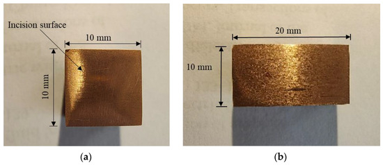
Figure 1.
Copper tool (a) top profile; (b) side profile with dimensions.
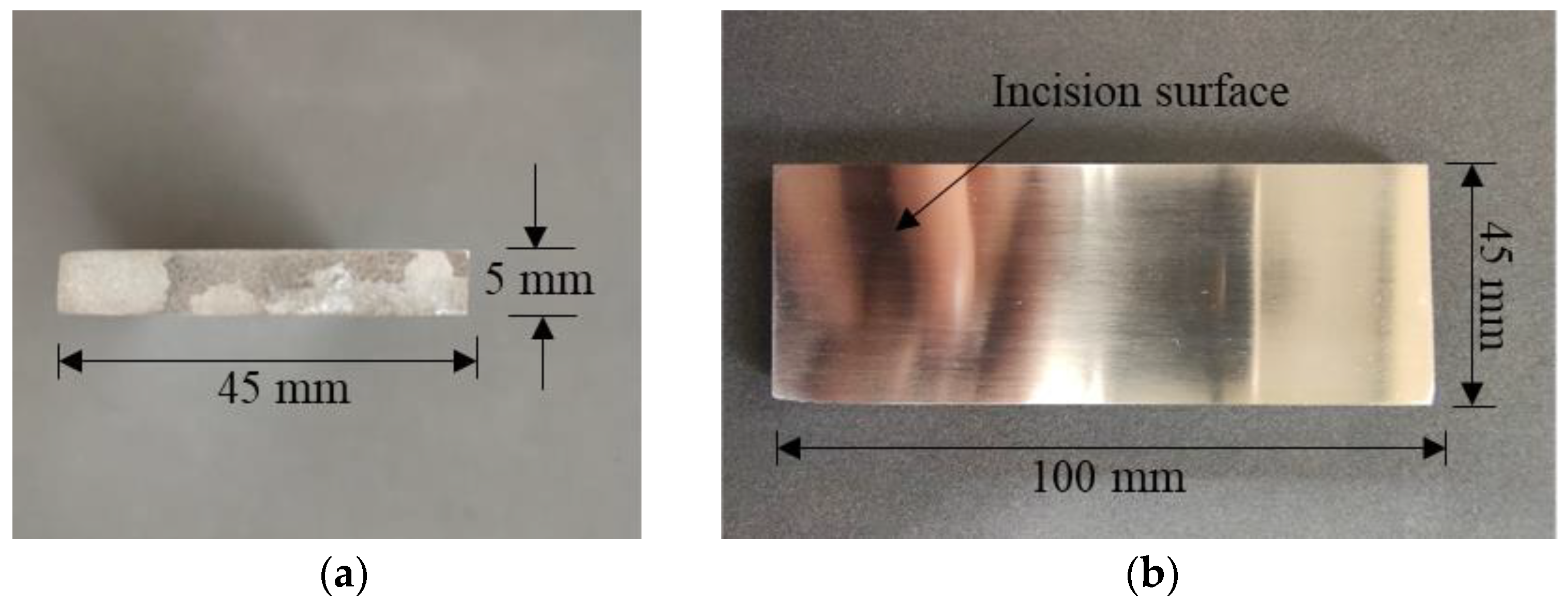
The workpiece was a cuboidal slab of the AZ-31 magnesium alloy of the given dimensions: 100 mm × 45 mm × 10 mm. The workpiece was cut into 2 parts longitudinally using Wire EDM to obtain two workpieces of a width of 5 mm each. This was carried out to increase the amount of available surface area to conduct more experiments (incisions). After the operation on the Wire EDM, the surface finish on the first set of 2 workpieces was improved using emery paper of 80, 320, 600, 800, 1200, 1500, and 2000 grit to obtain a mirror-like surface finish. Figure 2 shows the final dimensions and the mirror-like surface finish of the workpiece.
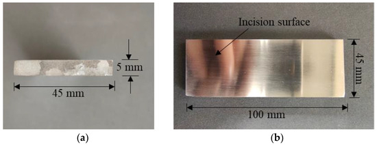
Figure 2.
(a) Width-wise side view of the workpiece; (b) top view of the workpiece with mirror-type surface finish where the incisions will take place.
2.3. Experimental Setup and Machining Using EDM
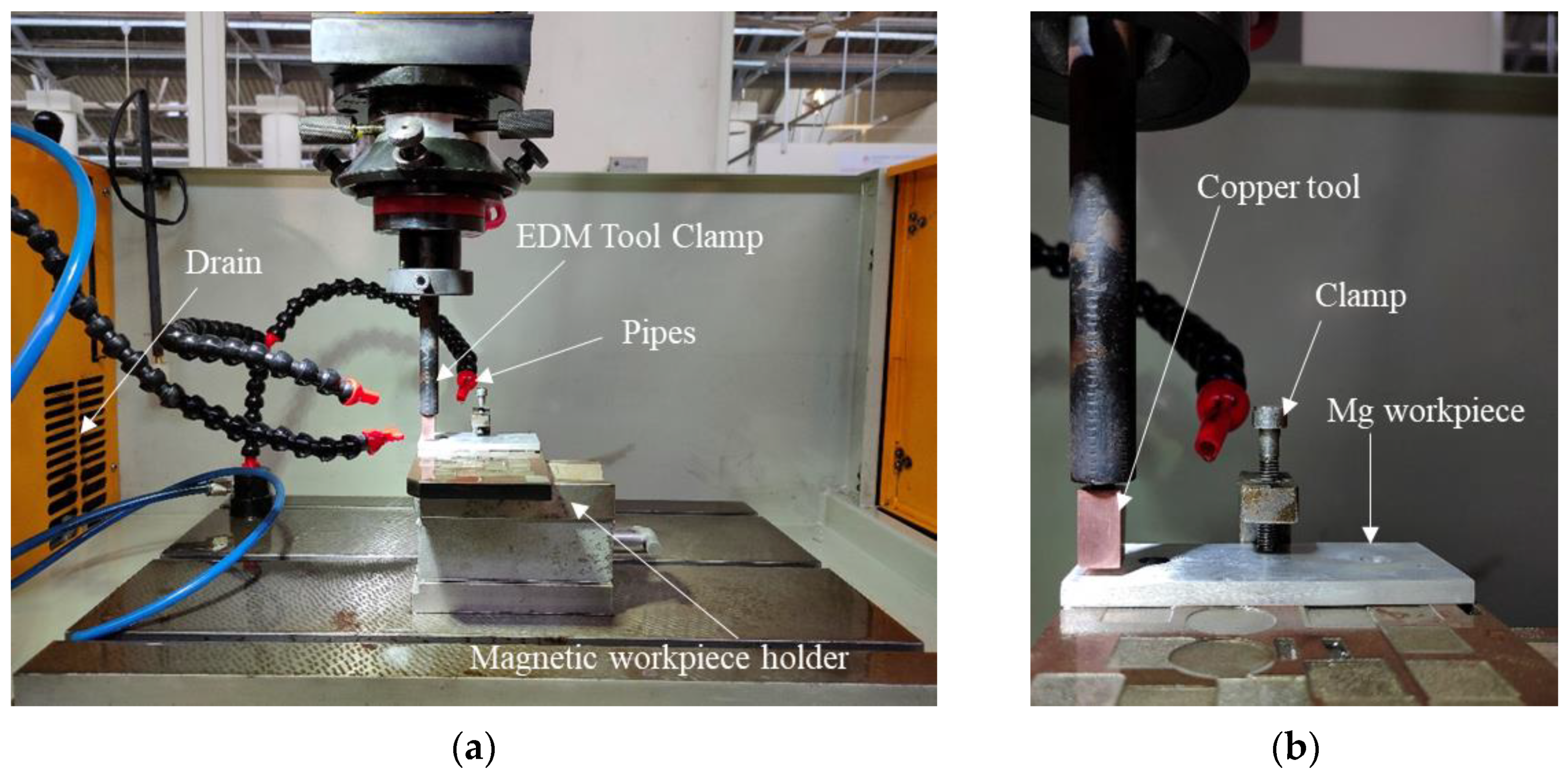
The EDM machine 50-A ZNC of Sparkonix Pvt. Ltd., Pune, Maharashtra, India having worktable dimensions of 700 × 420 mm is used in the current work. The maximum machine speed and current available for the machine were 400 mm/min and 50 A, respectively. The power supply was 415 V, 3-phase, and 50 Hz, and the available range of pulse on-time (Ton) was between 2 and 2400 µs. The tool clamp had a screw-like thread design; thus, the copper tool was screwed on the clamp for successful operation. The dielectric fluid used for the experiment was de-ionized water. Figure 3 shows the arrangement at the beginning of the experiment.
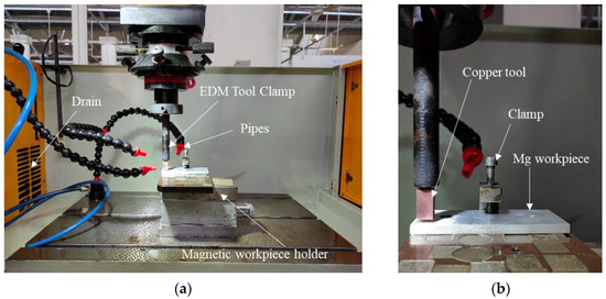
Figure 3.
(a) Experimentation setup of Sparkonix 50 A ZNC EDM; (b) clamp holding workpiece and copper tool in the tool clamp.
For the experiments, three different sets of values were selected for the following parameters: pulse on-time (Ton), pulse off-time (Toff), and current (I). An L-27 array method was used to generate the possible combinations of Ton, Toff, and I. The incisions were made using these new parameters at a depth of 0.3 mm. The servo voltage was kept constant at 45 V for all incisions, and the distance between each of the incisions was approximately 4 mm to accommodate all the experiments on the Mg workpiece surface. Before the experiment, the Mg workpiece and copper tool were prepared for the experiment by cleaning them of impurities in deionized water. Once they were cleaned, the copper tool was held in the EDM tool holder, and the workpiece was fixed on the magnetic holder using a clamp. They were cleaned in a similar way after each incision. After the completion of 27 incisions, the workpiece was once again cleaned, and 9 incisions were selected from the 27 for further investigation. The nine incisions were selected in a way that gave unique combinations of parameters with non-recurring values of current (I), pulse on-time (Ton), and pulse off-time (Toff). This selection of 9 parameters out of the 27 gave unique values and combinations for Ton, Toff, and I so that none of the combinations would match with any other working parameter. This selection was carried out to develop an insight into the parameters and how they affect the quality of the surface finish. Table 2 shows the input parameters used in the selected 9 incisions for the analysis.
Table 2.
List of selected nine combinations of parameters I, Ton, and Toff out of the L-27 array.
2.4. Surface Analysis Using Optical Microscope
Optical microscopy was used to obtain a deeper insight into the surface finish and texture of the Mg workpiece after machining on the Plug EDM. Images were taken at 2 different magnifications for all 9 samples. The objective magnifications chosen for the images were 5× and 10×. The total magnifications for the following were 50× and 100×, respectively.
2.5. Surface Analysis Using Profilometer
The instrument used for the profilometer test was the Dektak-XT Thickness Measurement Unit manufactured by BRUKER, USA. The travel length for the silicon carbide tip for the profilometer test was 2 mm, and it had a sensitivity of 524 µs. Three readings for each sample were taken, and the average value was noted down. This test was conducted to obtain quantitative information on the effects of selected working parameters on the surface finish of the workpiece.
3. Results
Before the start of machining, it was made sure that the Mg workpiece and the copper tool were parallel to each other, and to ensure this, an L-bracket and clamps were used. This facilitates full-area contact between the copper tool and the specimen’s surface. The tool and workpiece were cleaned thoroughly with de-ionized water to ensure no residue remained on the incision surface after the machining operation was completed. Figure 4 shows an image of the incisions carried out on the Mg alloy work specimen with all 27 incisions. Out of these, the selected nine incisions were as follows: 1, 5, 9, 11, 13, 17, 21, 24, and 25. The nine incisions had unique and non-recurring values of current (I), pulse on-time (Ton), and pulse off-time (Toff). A further investigation was conducted to assess the effect of these combinations of parameters on the surface roughness of the Mg workpiece after machining.
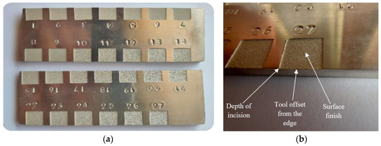
Figure 4.
(a) View of workpiece surface showing after going under operation of Plug EDM for the selected 27 parameter values (b) close view showing depth of the incision and other details.
3.1. Surface Analysis Using Optical Microscope
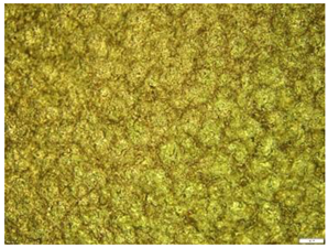
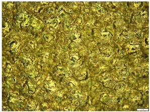
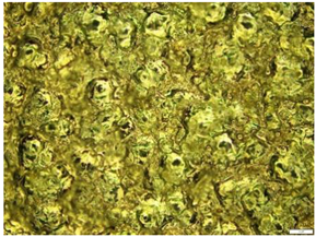
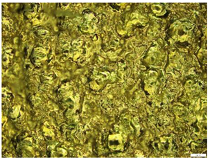
The surface images related to the 10× objective magnifications are shown in Table 3. It shows the optical microscopy images for four out of the nine selected samples at 10× magnification for each sample. After observing the samples under the microscope, it was noticed that with increasing values of the peak current, the pulse on-time, and the pulse off-time, surface roughness also increases.
Table 3.
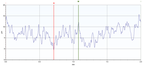
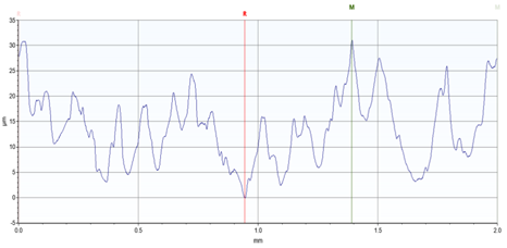
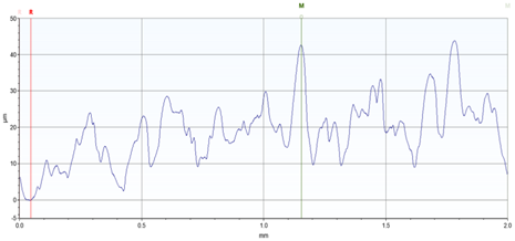
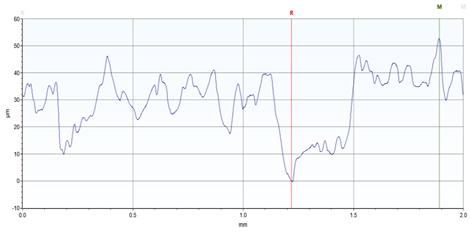
Optical microscopy images taken using 10× magnification lens and the surface profile obtained from the profilometer for selected incisions. (Refer to Table 2 for incision parameters).
3.2. Surface Analysis Using Profilometer
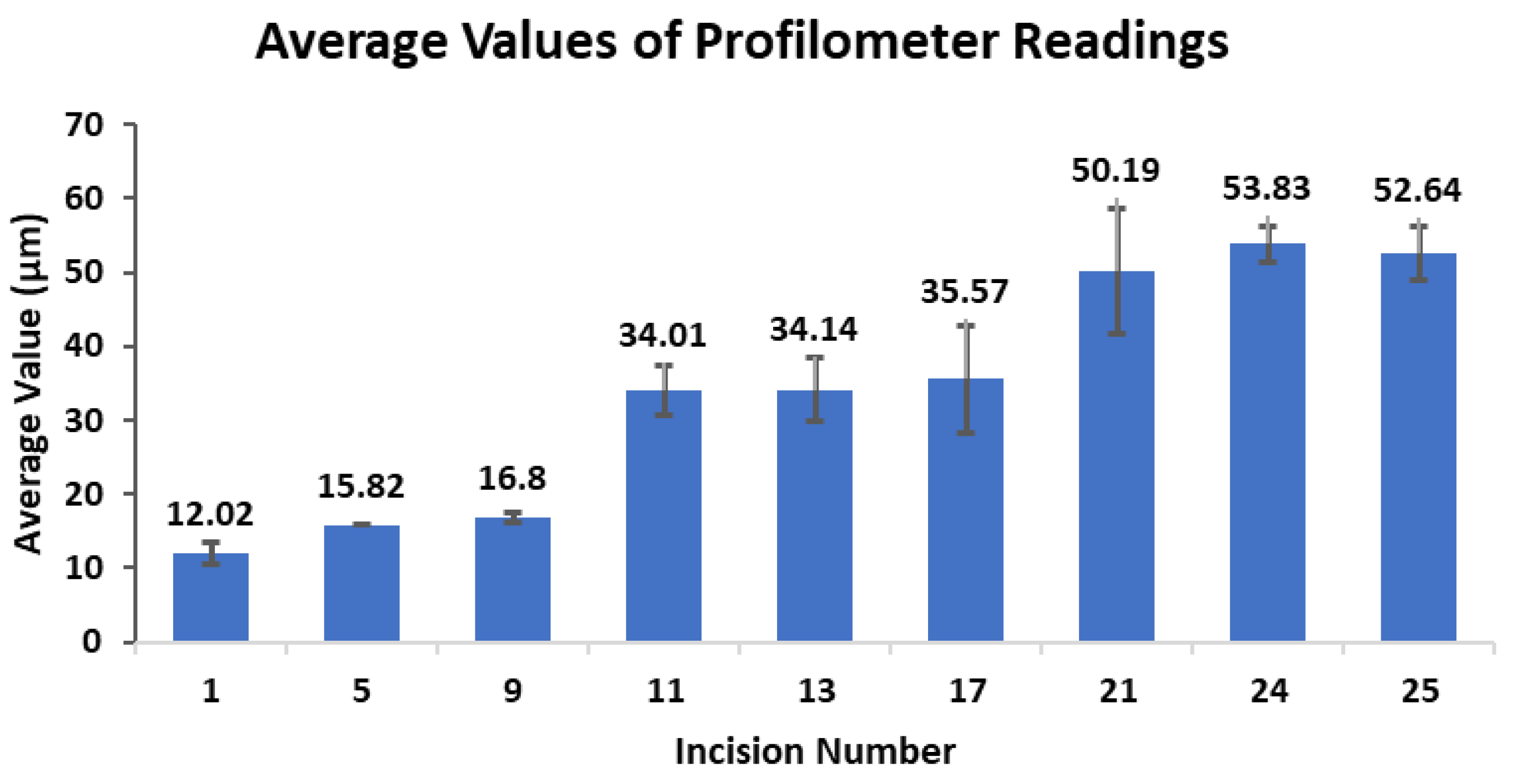
Through the profilometer test, it was noticed that with a higher peak current, pulse on-time, and pulse off-time combination, the surface roughness increases drastically. Three readings for each sample were taken, and their average value was noted down. Figure 5 shows the views of the imaging. Table 4 and Figure 6 show the readings taken for the profilometer test along with their average values and standard deviation, and Table 3 shows the graph for the same. The graph depicts the increasing value of surface roughness with increasing values of pulse on-time and current.
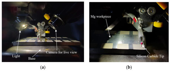
Figure 5.
(a) Close view of Dektak-XT Thickness Measurement Unit (BRUKER) shows the positioning of the specimen, (b) shows the profiling of the surface suing silicon carbide tip.
Table 4.
Values of profilometer test (Refer to Table 2 for incision parameters).

Figure 6.
Bar diagram showing the average roughness of the selected incisions measured using the profilometer.
4. Discussion
In the current work with the AZ-31 Mg alloy, it was noted that with low current values, the surface roughness was smooth, but the machining time was longer. Similarly, it was observed that the machining time for each operation was reduced with increasing values of current, but such an operation would result in a poor and rough surface finish. The optical microscopy images and profilometer data show the formation of craters of varying sizes and geometries, and this depends on the discharge energy. The discharge energy increases with an increase in Ton and I across the electrodes, which produces large-sized vapor bubbles that grow and collapse into a large-scale crater within the electric field, thus increasing the surface roughness value. In their work on the machining of the ZE41A magnesium alloy using a brass wire electrode (250 µm diameter) and de-ionized water as a dielectric fluid in a Wire EDM with various values of I, Ton, Toff, and servo voltage (V), Kumar R et al. (2022) [15] observed a similar pattern. That is, with increases in the values of I and Ton, an increase in the surface roughness values was observed, and the opposite was observed with the remaining two parameters. This means that higher I and Ton values and lower Toff and SV values resulted in a higher spark energy between the electrode and work sample, resulting in higher amounts of melting and erosion. This further led to more roughness and visible creator formations.
In a study by Gill R. S. et al. (2021) [16], a surface analysis for roughness was conducted on a Mg-4Zn alloy after going under Wire EDM operation. The analysis showed that the operation had a significant influence on the surface roughness of the alloy. It was noted that with an increase in the discharge current in the Wire EDM process, the resultant surface displayed large craters, and a higher density in micro-cracks and micro-pores increased the surface roughness value of the alloy. With the objective of research by Abdul-Rani A.M. et al. (2017) [17] being to improve the quality of the machined surface of an AZ-31 Mg alloy, it was noted that pulse on-time (Ton) was one of the more significant factors which affected the quality of the machined surface. Similar observations were made in an article by Somasundaram M. et al. (2022) [18], where it was found out that Ton was the most influential surface parameter affecting the quality of the surface finish.
5. Conclusions
During the various incisions performed, it was noted that the surface finish was most affected by the current (I) and pulse on-time (Ton). With increasing values of I and Ton, the time taken for the machining was reduced, and the surface roughness increased. Similarly, it was noted that the lower the values of I and Ton, the better and smoother the surface finish obtained, but at the cost of a higher machining time. It was noted that with a current of 1 Amp, the machining time was approximately 5 min for an incision of 0.3 mm. For the same incision depth but at a current value of 5 Amp, the machining time was reduced to approximately 30 secs. The incisions carried out with a 1 Amp current gave a smoother surface finish, and those with a 5 Amp current gave rough surface finishes on the Mg workpiece. The investigation of the effect of machining parameters on an AZ31 mg alloy plays an important role in the field of material processing. The outcome may help mechanists and manufacturers use this knowledge to balance machining time and surface quality to enhance manufacturing efficiency and quality assurance.
Author Contributions
Conceptualization by G.B. and V.M. experimental conduction and data analysis by S.B., A.A. and I.T. writing of original draft and preparation were conducted by S.B., A.A. and I.T. Draft reviewed by V.M. and G.B. Overall project supervision by V.M. and G.B. All authors have read and agreed to the published version of the manuscript.
Funding
This research received no external funding.
Institutional Review Board Statement
Not applicable.
Informed Consent Statement
Not applicable.
Data Availability Statement
The data used in this research article are not available for public sharing due to its ongoing nature as a running project.
Acknowledgments
We would like to express our sincere gratitude to the Department of Physics, Manipal Institute of Technology, Manipal Academy of Higher Education, Karnataka-576104, for providing access to the profilometer for the surface roughness analysis.
Conflicts of Interest
The authors declare no conflicts of interest.
References
- Crane, F.A.A.; Charles, J.A.; Furness, J.A.G. Selection and Use of Engineering Materials, 3rd ed.; Elsevier: Massachusetts, MA, USA, 1997; pp. 45–117. [Google Scholar]
- Yang, Y.; Xiong, X.; Chen, J.; Peng, X.; Chen, D.; Pan, F. Research advances in magnesium and magnesium alloys worldwide in 2020. J. Magnes. Alloys 2021, 9, 705–747. [Google Scholar] [CrossRef]
- Tan, J.; Ramakrishna, S. Applications of Magnesium and Its Alloys: A Review. Appl. Sci. 2021, 11, 6861. [Google Scholar] [CrossRef]
- Kasaeian-Naeini, M.; Sedighi, M.; Hashemi, R.; Delavar, H. Microstructure, mechanical properties, and fracture toughness of ECAPed magnesium matrix composite reinforced with hydroxyapatite ceramic particulates for bioabsorbable implants. Ceram. Int. 2023, 49, 17074–17090. [Google Scholar] [CrossRef]
- Pekguleryuz, M.O.; Kaya, A.A. Creep Resistant Magnesium Alloys for Powertrain Applications. Adv. Eng. Mater. 2003, 5, 866–878. [Google Scholar] [CrossRef]
- Aghion, E.; Bronfín, B.; Von Buch, F. Newly developed magnesium alloys for powertrain applications. JOM 2003, 55, 30–33. [Google Scholar] [CrossRef]
- Akyuz, B. Influence of Al content on machinability of AZ series Mg alloys. Trans. Nonferrous Met. Soc. China 2013, 23, 2243–2249. [Google Scholar] [CrossRef]
- Danish, M.; Yasir, M.; Mia, M.; Nazir, K.; Ahmed, T.; Ahmad, M.A.R. High speed machining of magnesium and its alloys. High Speed Mach. 2020, 10, 263–282. [Google Scholar]
- Ahuja, N.; Batra, U.; Kumar, K. Experimental investigation and optimization of wire electrical discharge machining for surface characteristics and corrosion rate of biodegradable Mg alloy. J. Mater. Eng. Perform. 2020, 29, 4117–4129. [Google Scholar] [CrossRef]
- Qiu, R.; Li, C.; Tong, W.; Xiong, D.; Li, Z.; Wu, Z. High-speed wire electrical discharge machining to create superhydrophobic surfaces for magnesium alloys with high corrosion and wear resistance. Mater. Corros. 2020, 71, 1711–1720. [Google Scholar] [CrossRef]
- Darras, B.M.; Khraisheh, M.K.; Abu-Farha, F.K.; Omar, M.A. Friction Stir Processing of Commercial AZ31 Magnesium Alloy. J. Mater. Process Technol. 2007, 191, 77–81. [Google Scholar] [CrossRef]
- Esmaily, M.; Svensson, J.E.; Fajardo, S.; Birbilis, N.; Frankel, G.S.; Virtanen, S.; Arrabal, R.; Thomas, S.; Johansson, L.G. Fundamentals and advances in magnesium alloy corrosion. Prog. Mater. Sci. 2017, 89, 92–193. [Google Scholar] [CrossRef]
- Umoren, S.A.; Solomon, M.M.; Madhankumar, A.; Obot, I.B. Exploration of natural polymers for use as green corrosion inhibitors for AZ31 magnesium alloy in saline environment. Carbohydr. Polym. 2020, 230, 115466. [Google Scholar] [CrossRef] [PubMed]
- Song, G.L. The Effect of Texture on the Corrosion Behavior of AZ31 Mg Alloy. JOM 2012, 64, 671–679. [Google Scholar] [CrossRef]
- Kumar, R.; Katyal, P.; Mandhania, S. Grey relational analysis based multiresponse optimization for WEDM of ZE41A magnesium alloy. Int. J. Lightweight Mater. Manuf. 2022, 5, 543–554. [Google Scholar] [CrossRef]
- Gill, R.S.; Kumar, K.; Batra, U. Surface Characteristics and Corrosion Behavior of Wire Electrical Discharge Machining Processed Mg-4Zn Alloy. J. Materi. Eng Perform 2021, 30, 2955–2966. [Google Scholar] [CrossRef]
- Abdul-Rani, A.M.; Razak, M.A.; Littlefair, G.; Gibson, I.; Nanimina, A.M. Improving EDM Process on AZ31 Magnesium Alloy towards Sustainable Biodegradable Implant Manufacturing. Procedia Manuf. 2016, 7, 504–509. [Google Scholar] [CrossRef]
- Somasundaram, M.; Kumar, J.P. Multi response optimization of EDM process parameters for biodegradable AZ31 magnesium alloy using TOPSIS and grey relational analysis. Sādhanā 2022, 47, 136. [Google Scholar] [CrossRef]


Disclaimer/Publisher’s Note: The statements, opinions and data contained in all publications are solely those of the individual author(s) and contributor(s) and not of MDPI and/or the editor(s). MDPI and/or the editor(s) disclaim responsibility for any injury to people or property resulting from any ideas, methods, instructions or products referred to in the content. |
© 2023 by the authors. Licensee MDPI, Basel, Switzerland. This article is an open access article distributed under the terms and conditions of the Creative Commons Attribution (CC BY) license (https://creativecommons.org/licenses/by/4.0/).