Proceeding Paper

The Design for the Reconstruction of Settling Tanks †

Department of Environmental Engineering, Faculty of Mining and Geology, VSB—Technical University of Ostrava, 17. listopadu 2172/15, 708 00 Ostrava-Poruba, Czech Republic
*
Author to whom correspondence should be addressed.
Presented at the 4th International Conference on Advances in Environmental Engineering, Ostrava, Czech Republic, 20–22 November 2023.
Eng. Proc. 2023, 57(1), 32; https://doi.org/10.3390/engproc2023057032
Published: 7 December 2023

Abstract

:
This article describes the design of the reconstruction of the mechanical and technological equipment of the settling tanks at the wastewater treatment plant in the municipality of Boskovice. The reconstruction was focused on the flocculation cylinder, the travelling bridge, the bridge drive, and the collection of the settling tank floating sludge.

1. Introduction

Settling tanks are the final construction objects of the biological wastewater treatment process, where active sludge is separated from wastewater and purified water flows into the receiving body, assuming that the facility in question is a mechanical–biological wastewater treatment plant. In some cases, the functionality of the settling tanks is demonstrated by numerical models [1,2,3]. After stabilisation [4] and dewatering, the treated sludge from the settling tanks can be used for reclamation works but also for the pyrolysis process [5].
This article deals with the design of the reconstruction of the machinery and technological equipment of the circular settling tanks of the Boskovice WWTP. It is a part of the intensification of this treatment plant, with a required capacity of 20,000 equivalent inhabitants.
The design was carried out with an emphasis on high reliability, long service life, and minimal maintenance. This innovation also included a proposal to replace the surface skimming with floating sludge spraying; the outlet of treated water into a reinforced concrete trough with a screw collector with a pump; the outlet of this into the floating sludge trough; and the outlet of the treated water using a submerged pipe with suction holes at the top.

2. Description of the Current State of the Settling Tanks before Reconstruction

The WWTP and its facilities are located in the cadastral territory of the town of Boskovice. It belongs to the Association of Water Supply and Sewerage of Towns and Municipalities. It serves for the treatment of wastewater from the town of Boskovice and some of its local parts, processing of waste from the sewage treatment, and disposal of waste from cesspools and septic tanks. Due to its size, it is also used to process sludge from the nearby small WWTPs. A separate sewerage system is used in the town. This means that sewage and rainwater are discharged separately through the sewerage network.
The existing WWTP was at the limit of its capacity and was also hydraulically overloaded by more than 250 m3/d. In accordance with the amendment to Water Act No. 254/2001 [6], it is probably necessary to increase the collection of wastewater, which already constitutes a significant part of the load. The WWTP was intensified to ensure proper treatment of wastewater from the town of Boskovice. At the same time, the collection of wastewater from cesspits and septic tanks, as well as the treatment of liquid sludge from smaller wastewater treatment plants, had to be enabled in order to meet the requirements of Government Regulation No. 401/2015 [7]. The investment project also included the reconstruction of the two existing settling tanks, which are used to capture biological sludge from the activation tanks by sedimentation. They are of circular shape with an internal diameter of 15 m.
The technological equipment consisted of a steel central column, on the top of which a ring collector was installed; a roofed flocculation cylinder with a deflector; a travelling bridge with bottom and surface skimming; a bridge drive via a rack bar; and a rail travel. In addition, it also included the collection of floating sludge, the automatic cleaning of the overflow edges and the tank crest located on the travelling bridge, and the outflow of the purified water through a collection trough with an overflow edge and a baffle.
The investor’s requirement was to address the inadequate removal of floating sludge. This sludge was generated because of the presence of certain filamentous micro-organisms, characterised by a strongly hydrophobic cell surface and the formation of biologically surface-active substances. During aeration in the activation tanks, these microorganisms caused the formation of a biological foam in which other microorganisms of the activated sludge were trapped.
The existing system consisted of fixed scraping plates, suspended from a swing bridge and arranged so that the sludge was moved by centrifugal force to the perimeter of the tank where it was carried to the floating sludge cesspool by a tilting scraper. The ST level behind the scraping plates was sprayed with partially treated water through a submersible pump and a pipe distribution system suspended from the bridge railing. The spread of floating sludge is shown in Figure 1. Despite all these measures, the drainage of the floating sludge was not satisfactory.

3. Reconstruction Plan

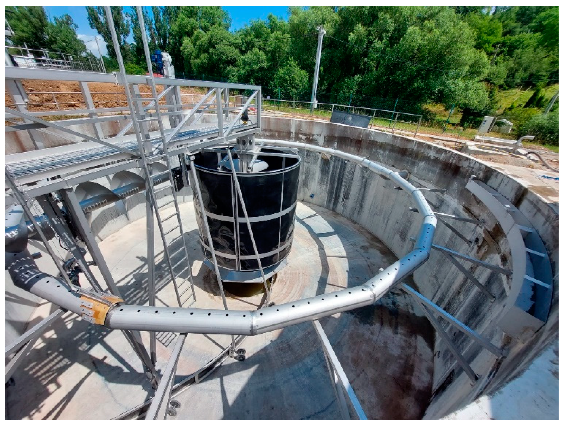
In the existing settling tanks, a complete replacement of the mechanical and technological equipment with new ones was proposed. It consists of a new supporting central steel column, flocculation cylinder, rectifying deflector, travelling bridge with bottom scraping, and a system of floating sludge removal, using a surface screw and a pump with a height-adjustable overflow cesspool. The outlet flows into the floating sludge trough. The hot-dip galvanised steel structure has been replaced by stainless steel. The outflow of purified water from the ST was redesigned. Instead of the existing reinforced concrete outlet troughs, an underwater collection using submerged perforated pipes was designed. The level in the settling tanks is found at the overflow edge in the treated water discharge manholes, where the water continues to drain to the Parshall flume.

3.1. Flocculation Cylinder

One of the key features of a flocculation ST is the regulated flow in the flocculation cylinder. The incoming activation mixture is ejected from the inflow column through the outlet openings to the wall of the flocculation cylinder. The inflowing activation mixture drops at the flocculation cylinder wall due to its density and returns upwards through the centre of the flocculation cylinder. This arrangement results in flocculation, i.e., the adherence of small flakes of activated sludge to large ones. The second characteristic feature of this arrangement is the limitation of the flow density. Below the edge of the flocculation cylinder, part of the mixture corresponding to the outflow quantity is separated and goes into the ST separation area. These features must be maintained for the proper operation and high efficiency of the ST [8].
Good flocculation is a prerequisite for effective sludge separation in the ST. By flocculation, we mean precipitation and floc formation. The diameter of the flocculation cylinder should be approximately 33% of the ST diameter. The immersion depth is recommended to be around 67% of the tank depth.
The flocculation cylinder has been designed as a lightweight structure suspended from a central column, consisting of four identical sections connected by bolted joints. The wall is made of PE foil and is reinforced around the perimeter with stainless steel profiles. The cylinder is height-adjustable via four threaded rods. The designed diameter is 3.8 m and the height is 3.65 m. The cylinder is sunk to a depth of 3.4 m. During the designing process, an all-stainless steel flocculation cylinder was discussed. The advantage is its longer lifetime; the disadvantage is its higher weight and higher investment costs. The next point for discussion was the roofing of the flocculation cylinder. The advantage of this measure is the partial reduction of smell; the disadvantage is the lack of the possibility to visually check the level in the cylinder.

3.2. Travelling Bridge

It is used to operate the ST, as well as acting a carrier for the floating sludge collector and for scraping the bottom of the tank.
It is a frame structure with a length of 7750 mm and a width of 1260 mm, mounted with one end on the inflow column and the other on the head of the tank wall. The rotational movement is enabled by a friction bearing connecting the bridge to the column; two driven travelling wheels above the tank wall; and one driving wheel suspended from the bottom side of the bridge, which is pressed against the inner vertical wall of the ST. The friction bearing is maintenance-free. The material used is polyethylene and the diameter of the bearing is 630 mm. The driven travelling wheels are 405 mm in diameter. A tank head scraper is mounted in front of these wheels. The driving wheel is suspended under the bridge. It rotates the travelling bridge by a rolling motion on the inner wall of the tank. The floor is made of stainless steel grating. The railings are 1100 mm high. They are divided in the middle of the railing height by a dividing handrail and in the lower part by a kick plate.
At the end of the bridge, near the middle of the ST, there is an opening gate. On the handrails, there are brackets for the floating sludge collector, bowls with a pump for the floating sludge, a winch for operating this equipment, and an electrical switchboard. A floating sludge pipe is routed under the bridge to allow the sludge to flow into a trough at the ST wall or into a flocculation cylinder. The bottom beam is fitted with draw rods used to scrape the bottom of the tank and sensors, which are used to start and stop the pumping of floating sludge into the sump. All devices are connected to the bridge via sleeves and are, therefore, adjustable. A set of brushes is suspended on the bridge above the outlet pipe to clean the upper part of the pipe.
Access to the bridge is possible by means of tipping steps. There are grab handles on the handrails. An emergency start/stop button is installed at the point of entry for the quick stopping of the bridge.

3.3. Bridge Drive Mechanism

It is used to set the travelling bridge, the floating sludge collection, and the bottom scraping into motion. It consists of a carrier plate, drive wheel, and drive. It is designed to have the power of 0.25 kW and 0.7 A. The starting current is 2.2 A. It operates non-stop as standard. In the event of a power failure, an automatic restart occurs. Manual control of the drive is enabled in the bridge switchboard. The drive wheel has Ø of 530 mm. To ensure correct operation, a pressure system made of flexible rubbers has been designed. The wheel tyre is fitted with a winter tread.

3.4. Floating Sludge Collection

The device is used to remove floating sludge from the ST surface and to discharge it outside the ST area.
The floating sludge collector system consists of two floating screw conveyors. The rotating motion of the screws moves the sludge into a hydraulically formed scraper container, which is connected to the screws.
Due to the floating arrangement of the screws and the fact that the floating sludge container is connected to the screws, the overflow height remains constant, even when the water level fluctuates.
In addition, the overflow height relative to the floating screws can be precisely adjusted and set using an adjustment wrench. The overflow height is, thus, used to set the desired amount of discharged sludge on one side and the desired mixing ratio of floating sludge, water, and air on the other side.
In this way, floating sludge layers of any consistency and thickness, even sludge bolsters and larger closed sludge covers, can be safely and quickly pumped out by a submersible pump fitted in the next part.
Water level fluctuations of up to 500 mm are possible, e.g., during flow changes and especially with submerged discharge devices or under wind loads, where the floating sludge scraper balances the sludge with millimetre precision using the weight-balanced bearings of the rotary screw conveyor arms.
Thanks to the floating screw arrangement and the connection of the scraping hopper to the floating screws, the SSR floating sludge scrapers ensure that the scraping hopper functions consistently without the need for operator intervention, even with these changes.
The modular design of the floating sludge removal system and standardized fasteners allow the simple and stable installation of the system in any separator, on any scraper design, and for any discharge system, with almost no restrictions.
The system is particularly suitable for retrofitting to existing circular scraping systems as it fully automatically compensates for any existing design inaccuracies caused by the floating arrangement.
The independent and precise adjustment of the floating screws to fluctuating water levels ensures the safe and simple fully automatic operation of the floating sludge collector.
With the aid of a time-controlled floating sludge pump, the mixture of sludge, water, and air is extracted at the required concentration and with a floating sludge volume of up to 50 m3/day.
All materials used in the floating sludge collector are carefully selected for extremely long life and minimal maintenance.
Stainless steel is used for all wetted parts, UHMWPE for the maintenance-free bearings, UHMWPE and POM for the maintenance-free chain drive, and weatherproof elastomers resistant to atmospheric exposure for the seals. Commercially available materials are used only for the floating sludge collectors, submersible pump, and worm gear motor.
The drive unit is maintenance-free and is equipped with a lifetime lubricated gear motor of 0.18 kW and 0.59 A. The starting current is 2.14 A. The output shaft of the gear motor is in a special stainless steel design to prevent corrosion of the sealing surfaces and subsequent damage to the seal itself. Since the bearings are completely unloaded using the floating method, operation and maintenance work is limited to infrequent visual inspections, occasional re-setting of the slurry tank overflow height, and annual oil changes for the submersible motor pump.
For service work on the pump, it can be easily raised to operating level by means of a lifting device, sliding guide and special elastomer seals on the suction and pressure sides.
The new mechanical and technological equipment of the settling tank are presented in Figure 2.

4. Conclusions

The design of the mechanical and technological equipment of the settling tank for the Boskovice wastewater treatment plant was carried out in accordance with the technological principles valid for this type of equipment.
A static assessment was carried out for the inflow column, which resulted in the conclusion that the given cross-section, under the worst-case condition of an empty tank and full load, is satisfactory.
A leakage test in accordance with CSN 75 0905 [9] was successfully performed on the reconstructed settling tank. The test has confirmed that the reconstructed settling tank is designed to be watertight.
The test operation confirmed that the requirement for an improved floating sludge removal capability was met. Thanks to the flexible bottom scraper wheels that follow the unevenness of the cambered concrete, the functional properties of the equipment have also improved in this respect.

Author Contributions

Conceptualization, P.B. and V.V.; methodology, P.B. and V.V.; formal analysis, P.B. and V.V.; investigation, P.B., V.V. and T.D.; resources, P.B. and V.V.; writing—original draft preparation, P.B., V.V. and T.D.; writing—review and editing, V.V. and T.D.; visualization, P.B., V.V. and T.D.; supervision, P.B. and V.V.; funding acquisition, T.D. All authors have read and agreed to the published version of the manuscript.

Funding

This research received no external funding.

Institutional Review Board Statement

Not applicable.

Informed Consent Statement

Not applicable.

Data Availability Statement

The authors declare that all data supporting the results of this research are available in this article.

Acknowledgments

This article has been produced with the financial support of the European Union under the REFRESH—Research Excellence For REgion Sustainability and High-tech Industries project number CZ.10.03.01/00/22_003/0000048 via the Operational Programme Just Transition.

Conflicts of Interest

The authors declare no conflict of interest.

References

  1. Bürger, R.; Diehl, S.; Farås, S.; Nopens, I. On Reliable and Unreliable Numerical Methods for the Simulation of Secondary Settling Tanks in Wastewater Treatment. Comput. Chem. Eng. 2012, 41, 93–105. [Google Scholar] [CrossRef]
  2. Abusam, A.; Keesman, K.J. Dynamic Modeling of Sludge Compaction and Consolidation Processes in Wastewater Secondary Settling Tanks. Water Environ. Res. 2009, 81, 51–56. [Google Scholar] [CrossRef] [PubMed]
  3. Bürger, R.; Diehl, S.; Nopens, I. A Consistent Modelling Methodology for Secondary Settling Tanks in Wastewater Treatment. Water Res. 2011, 45, 2247–2260. [Google Scholar] [CrossRef] [PubMed]
  4. Pilarski, G.; Kyncl, M.; Stegenta, S.; Piechota, G. Emission of Biogas from Sewage Sludge in Psychrophilic Conditions. Waste Biomass Valor. 2020, 11, 3579–3592. [Google Scholar] [CrossRef]
  5. Kubonova, L.; Janakova, I.; Malikova, P.; Drabinova, S.; Dej, M.; Smelik, R.; Skalny, P.; Heviankova, S. Evaluation of Waste Blends with Sewage Sludge as a Potential Material Input for Pyrolysis. Appl. Sci. 2021, 11, 1610. [Google Scholar] [CrossRef]
  6. CZECH REPUBLIC. Act No. 254/2001 Coll. on Water and Amendments to Certain Acts (Water Act). In Collection of Laws; Printing House of the Ministry of the Interior: Praha, Czech Republic, 2001; No. 98. [Google Scholar]
  7. CZECH REPUBLIC. Government Decree No. 401/2015 Coll. on Indicators and Values of Permissible Pollution of Surface Water and Wastewater, Details of Permits for Discharge of Wastewater into Surface Water and Sewers and on Sensitive Areas. In Collection of Laws; Printing House of the Ministry of the Interior: Praha, Czech Republic, 2015; No. 166. [Google Scholar]
  8. GRAU, P. Nové Řešení Výtokových Otvorů z Rozdělovacího Hrnce Flokulačních Dosazováků; AquaNova: Praha, Slovakia, 1999. [Google Scholar]
  9. CSN 75 0905. Water Suply and Sewerage Tanks—Testing of Water-Tightness; ČSN: Praha, Czech Republic, 2014. [Google Scholar]
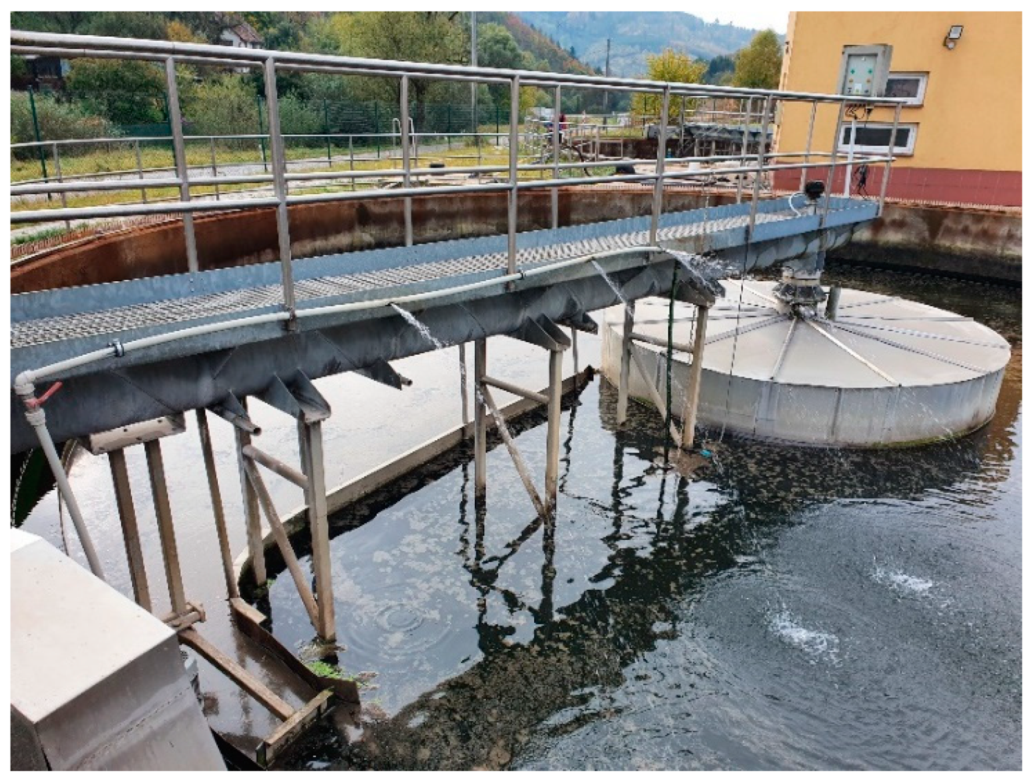
Figure 1. Spread of floating sludge.
Engproc 57 00032 g001
Figure 2. New mechanical and technological equipment of the settling tank.
Engproc 57 00032 g002
Disclaimer/Publisher’s Note: The statements, opinions and data contained in all publications are solely those of the individual author(s) and contributor(s) and not of MDPI and/or the editor(s). MDPI and/or the editor(s) disclaim responsibility for any injury to people or property resulting from any ideas, methods, instructions or products referred to in the content.