Abstract
This paper shows the implementation and performance analysis of motion control algorithms for a 3D Concrete Printing system based on an industrial robotic arm. This work is part of the project of digital fabrication of low-cost housing. Regarding the technological architecture integrated in the present work, the hardware devices used are the EPSON C12 industrial robot arm and the RC700-A controller, and the software tools are Fusion 360 and RC+. To evaluate the point extraction and sequencing algorithms of a 3D structure and the motion control algorithms of the robot arm, three test wall models were designed: a semi-circle with horizontal undulations, a semi-circle with vertical undulations and an orthohedron without undulations. For the performance analysis, 140 trajectory times were extracted for each test model. The extracted values are the trajectory time intervals of the wall model envelope for each layer and of the internal trajectory of the wall model infill. Due to the increasing and decreasing trends of time for specific cases, it was concluded that in the working area of the robot arm, there are parts in which the robot is more efficient and therefore the joints offer less inertia for certain types of movements, for example straight or curved movements and short or long movements.
1. Introduction
In the world, according to the United Nations, the number of people who do not have decent housing is worrying: approximately 1.6 billion people live in inadequate housing and about 900 million live in informal settlements or camps [1]. Similarly, in Ecuador, we find that about 600,000 families do not have their own home, which is why meeting the need for housing has become urgent [2]. Due to the development and introduction of Industry 4.0, digital manufacturing is gaining momentum as it allows a more precise design process and opens up an opportunity to manufacture a great diversity of part geometries compared to traditional manufacturing. Together with 3DCP printing (3D Concrete/Concrete Printing), it allows the materialization of wall blocks or houses, so the printing technology will be a determinant for the heterogeneous geometry to be obtained [3].
In parallel to traditional 3D printing technologies, several companies began to test the creation of 3D ceramic parts, which were the basis for large-scale printing in the construction area. In 2014, the Chinese company Winsun, a pioneer in this area, printed several houses in a period of 24 h, with a method of printing in parts or blocks, which were moved to the place where they would be implemented. In such a way, different techniques and models of 3D printers were tested for different needs [4].
For 3D printing in the construction sector, there are factors to take into account, such as total printing time, costs, materials and printing accuracy. There are two techniques that have been predominant since the inception of 3D Concrete Printing (3DCP) [5,6].
The extrusion-based technique: it works via deposition of material layer by layer through a nozzle that is located on a Cartesian robot or six-axis robotic arm. This technique is used for large-scale construction or printing of complex geometries, depending on the type of robot to be used [7].
Powder-based technique: it works by depositing a binder liquid in a guided manner on the CAD model to be created, then a powder mixture is added for the solidification process. This technique is used for the fabrication of modular components or small-scale constructions [5].
In the academic environment, there are some challenges addressed around 3DCP technology. In [8], a system for mobility limitation for the fabrication of complex structures is presented. In [9], a 3D printing system of a post-tensioned concrete beam is presented. In this project, an industrial robot arm with 6 degrees of freedom is used. In [10], a project for fabrication of structures from a robotic system is presented. This system was implemented at laboratory scale. On the other hand, in [11], the extrusion material is addressed, and the authors conclude that the optimum material should have a balanced behavior of elasticity–viscosity–plasticity properties. The authors performed tests with an industrial robotic arm at a speed of 30 mm/s. Finally, with the aim of analyzing the extraction of key points from a solid intended to be 3D printed, [12] was analyzed. This study presents the use of CAD files for layered 3D printing.
Based on the literature research and to address the technological subsystem (software and hardware) of the digital fabrication project to generate low-cost housing, the objective of this paper is to develop the motion control algorithms and analyze the laboratory-scale performance of the industrial robotic arm applied to 3D concrete printing systems.
The layout of this paper consists of Section 2, Materials and Methods, which addresses the hardware and software architecture of the system and the simulation of the algorithms; Section 3, Results and Discussion, which addresses the physical implementation of the system, the data extraction and the discussion around the trends identified in the data, and finally Section 4, which summarizes the conclusions of the work.
2. Materials and Methods
The present section is composed of the description of the hardware and software architecture of the system and the description of the design and simulation of the algorithms of the experimental system.
2.1. Hardware and Software Architecture of the System
Figure 1 shows a diagram of the system to be designed and implemented composed of software and hardware elements. The workflow starts with the modeling of the test block or wall with the Fusion 360 program. The finished design is exported in the “.step” format compatible with the EPSON RC+ 7.5 R2 software. In the latter, we proceed to elaborate the algorithm, introducing the initial configuration, then we import the designed model; using the CAD To Point 7.5 tool, we extract the points of the wall block.
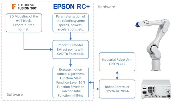
Figure 1.
Hardware and software architecture of the system.
Once the points of the layers have been obtained, with the “main” function configured, different functions are created to control the movement of the robot arm, generating point-to-point movements for the formation of the wall and the filling. Once the algorithm is completed, from the computer connected via USB to the EPSON RC700-A controller (Seiko Epson Corp., Suwa, Japan), the code is implemented to perform the tests with the EPSON C12 robotic arm (Seiko Epson Corp., Suwa, Japan).
Regarding the hardware devices that are part of the system, these include the EPSON C12 industrial robot arm, which has 6 axes with payload capacity of 12 kg, range up to 1400 mm and accuracy of +/−0.050 mm [13], and the EPSON RC700-A controller, which is a programmable device in SPEL+ language and has digital input/output and Ethernet TCP/IP communication interfaces [14].
The following software tools were used for the development and implementation of the system: Fusion360 was used for the design of the geometric structure intended for 3D printing. EPSON RC+ was used for the implementation of the motion control algorithm of the EPSON C12 robot arm, and the 3D structure point set extraction algorithm.
2.2. Design of the 3D Models to Be Printed
The model of the wall structures to be printed was designed in Autodesk Fusion 360 2.0 software. Three test models were designed, whose approximate dimensions of the envelope are 1500 × 250 × 490 mm. These designs will be used to evaluate the behavior of the robot in terms of trajectory control and robot movement times. Figure 2 shows the three 3D designs corresponding to the test walls.
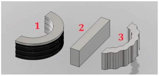
Figure 2.
Three-dimensional designs corresponding to the test walls: (1) semi-circle with vertical undulations, (2) orthohedron without undulations, and (3) semi-circle with horizontal undulations.
For the first test design, we took into account geometrical considerations of the 3D-printed housing prototype of the Italian company WASP. The main guidelines of our design are as follows. The design has a 3D semicircle envelope with undulations perpendicular to the base. Each designed layer will have a height of 7 mm, because the material to be deposited has this height. The first 10 layers will have a reduction in radius of 3 mm with respect to the previous one. The next 10 layers will have an increase in radius of 3 mm with respect to the previous one. The second test design is a traditional rectangular wall. The third test design has a geometry of a semicircle with undulations along its perimeter.
2.3. Extraction and Processing of Points from the 3D Model
The CAD To Point tool available in EPSON software is used to extract the points of interest from the 3D design. The design is imported, the extraction is parameterized and finally a table of points is generated. The points of interest of the resulting table are those points that belong to the 3D design envelope and that will be used to generate the movements of the robotic arm.
Regarding point processing, this phase is necessary to link the points in an orderly manner and thus generate the routes that the robot will travel and manufacture. The final part of this stage is the generation of the robot arm movements between the consecutive coordinates of the 3D structure.
2.4. Simulation of Motion Control Algorithms
Once the points of the 3D structure have been extracted and ordered and the control algorithms of the robot movements have been developed, the simulation of the system is carried out. Figure 3 shows the simulation in the EPSON RC+ environment. The red points belong to the design of the 3D structure. These points show 70 layers, and the blue points indicate the path that the robot arm is performing while running the simulation. Figure 3a shows the robot path over the 3D structure envelope and Figure 3b shows the robot path over the 3D structure infill.
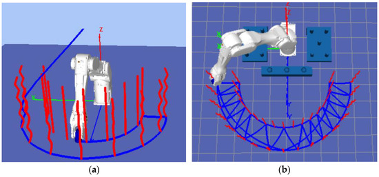
Figure 3.
Epson RC+ simulation environment of the robotic arm motion control algorithms: (a), robot path over the 3D structure envelope; (b), robot path over the 3D structure infill.
3. Results and Discussion
This section presents the results of the implementation of the motion control algorithms in the physical system composed of the EPSON C12 robot arm and the RC700-A controller. In addition, an analysis of the travel times for each of the test blocks will be performed.
3.1. Testing with the EPSON C12 Physical Robot
Figure 4 shows the EPSON C12 industrial robot arm running the path of the 3D designs loaded into the software. It should be noted that at the current stage of the project, the material extruder is not yet integrated to the robot arm. Figure 5 shows the software user interface during program execution on the RC700-A controller, Figure 5a shows the execution of the test wall 1 print program, Figure 5b shows the execution of the test wall 2 print program, Figure 5c shows the execution of the test wall 3 print program, and finally, Figure 5d shows the execution times for each layer. The green points belong to the design of the 3D structure and the blue points indicate the path that the robot arm is performing.
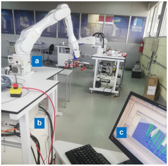
Figure 4.
Industrial robot arm running the path of the 3D designs loaded into the software. (a) EPSON C12 Robot arm, (b) EPSON RC700-A Controller, (c) computer to perform real-time visualization of the positions and times of the robot movements.
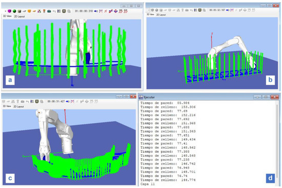
Figure 5.
Software user interface during algorithms execution on the RC700-A controller. (a) Execution of the test wall 1 motion control program, (b) execution of the test wall 2 motion control program, (c) execution of the test wall 3 motion control program, and (d) execution times for each layer.
3.2. Analysis and Discussion of Results
This section shows the record of the travel times obtained by the robot arm at the moment of executing the movements to locate the end effector in the coordinates belonging to the three test walls. The total travel time of the envelope and the filler is recorded for each of the 70 layers and for each of the three test walls; a total of 420 time values are obtained.
Figure 6 shows the fabrication time plot of the 70 layers of the envelope (a) and infill (b) for test wall design 1. The test designs are shown in Figure 2.
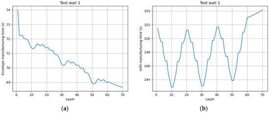
Figure 6.
Manufacturing time plot of the 70 layers of the envelope (a) and infill (b) for test wall design 1.
The following aspects are observed in Figure 6a:
- The first layer is slower than the others. This is because the robot starts from an idle position.
- The travel time of the layer is decreasing as the wall is being manufactured, with approximately 4 s difference between the printing of the first and last layer. This is because the new positions correspond to segments of the work area where the robot is slightly less efficient.
- Three depressions are identified in the graph due to the design of the wall, since it has three local minima in its vertical path.
The following aspects are observed in Figure 6b:
- It has three local minima due to the geometry of the wall.
- There is a trend of increasing travel time per fill layer; this trend is contrary to the envelope travel.
A preliminary explanation of the above analysis is that the performance of the actual robot arm is altered by the running time, i.e., a longer running time corresponds with a decrease in the task execution times. However, to contradict this hypothesis, it is seen that in Figure 6b, the fill time increases for each layer traversed. Consequently, it is concluded that in the working area of the robot arm, there are parts in which the robot is more efficient and therefore the joints offer less inertia for certain types of movements; for example, straight or curved movements and short or long movements.
Figure 7 shows the fabrication time plot of the 70 layers of the envelope (a) and infill (b) for test wall design 2.
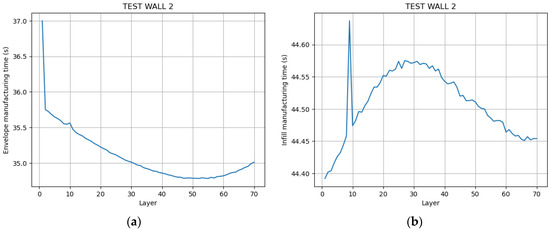
Figure 7.
Manufacturing time plot of the 70 layers of the envelope (a) and infill (b) for test wall design 2.
Figure 7a shows the following aspects:
- The first layer is slower than the others. This is due to the fact that the robot starts from a resting position.
- There is a minimum change in the travel time as the vertical displacement of the manufactured layer increases. From layer 2 to layer 52, we can observe a difference of 0.970 s, and from layer 52 to layer 70, the change is 0.229 s.
This reinforces the previous conclusion that the printing plane and the type of movement influences the trajectory travel times of the robot arm.
With respect to Figure 7b, two intervals can be seen: one interval of increase and one interval of decrease of the layer travel time. The conclusion that the printing plane and the type of movement influences the travel times of a robot path is more evident in this test design, since here, the design is an Orthohedron; therefore, the path of all the layers is exactly the same size, and the only parameter that changes is the height of the layer to be manufactured.
Figure 8 shows the fabrication time plot of the 70 layers of the envelope (a) and infill (b) for test wall design 3. As in the two previous cases, there is a tendency to decrease the envelope travel time as the robot advances in the fabrication of the upper layers, and, in addition, there is a tendency to increase the filler travel time as the robot advances in the fabrication of the upper layers.
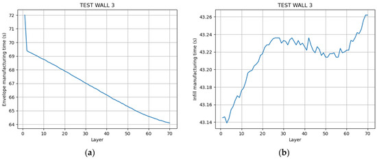
Figure 8.
Manufacturing time plot of the 70 layers of the envelope (a) and infill (b) for test wall design 3.
As the system advances to the upper layers, the time decreases, as shown in Figure 6a, Figure 7a and Figure 8a. This characteristic is linked to the simplicity of the path of the envelope with respect to the filling. The points of the envelope are closer to each other, so the robot does not have to accelerate or decelerate abruptly during the entire path. Meanwhile, the infill points are farther apart, so the robot generates velocity changes at the beginning and end of the motion sections. The source data for Figure 6, Figure 7 and Figure 8 can be found in the supplementary file of this article, Table S1.
4. Conclusions
The performance of motion control algorithms for a 3D Concrete Printing system based on an industrial robotic arm was implemented and analyzed. The integrated technological architecture consisted of the following elements: the EPSON C12 industrial robot arm, the RC700-A robot controller, and the software tools Fusion 360 and RC+.
With respect to the performance analysis of the system’s motion control algorithms, trends of increasing and decreasing motion execution times were identified for specific cases. It was concluded that in the working area of the robot arm, there are parts in which the robot is more efficient, and therefore the joints offer less inertia for certain types of movements; for example, straight or curved movements and short or long movements.
Supplementary Materials
The following supporting information can be downloaded at: https://www.mdpi.com/article/10.3390/engproc2023047009/s1, Table S1: Manufacturing times of the 70 layers of the envelope and the infill for Test Wall designs 1, 2 and 3.
Author Contributions
Conceptualization, methodology, C.C.-C. and L.S.; software, L.S. and D.C.; validation, L.S. and D.C.; writing—original draft preparation, C.C.-C. and R.S.; writing—review and editing, C.C.-C., R.S. and R.C.; supervision, C.C.-C. and R.C.; project administration and funding acquisition, C.C.-C. and R.C. All authors have read and agreed to the published version of the manuscript.
Funding
This research was funded by Universidad Tecnica Particular de Loja, grant number PROY_ARTIC_CE_2022_3667.
Institutional Review Board Statement
Not applicable.
Informed Consent Statement
Not applicable.
Data Availability Statement
Data are contained within the article and supplementary materials.
Conflicts of Interest
The authors declare no conflict of interest.
References
- Millones de Personas Viven Sin Techo o en Casas Inadecuadas, un Asalto a la Dignidad y la Vida|Millions of People Live Homeless or in Inadequate Housing, an Assault on Dignity and Life. Available online: https://news.un.org/es/story/2018/07/1437721 (accessed on 20 August 2023).
- Casi 600.000 Familias en Ecuador no Tienen Vivienda Propia|Nearly 600,000 Families in Ecuador Do Not Have Their Own Home. Available online: https://www.primicias.ec/noticias/sociedad/familias-ecuador-sin-casa-propia/ (accessed on 21 August 2023).
- Adam, J.O. Fabricación Digital: Introducción al Modelado e Impresión 3D; Ministerio de Educación, Cultura y Deporte: Madrid, Spain, 2016. [Google Scholar]
- Wu, P.; Wang, J.; Wang, X. A critical review of the use of 3-D printing in the construction industry. Autom. Constr. 2016, 68, 21–31. [Google Scholar] [CrossRef]
- Sonwalkar, S.P. Roadmap for Adopting 3D Concrete Printing Technology for Production of Affordable Houses. Master’s Thesis, University of Twente, Deventer, The Netherlands, 2020. Available online: http://essay.utwente.nl/83162/ (accessed on 10 July 2023).
- Chen, Y.; Jansen, K.; Zhang, H.; Romero Rodriguez, C.; Gan, Y.; Çopuroğlu, O.; Schlangen, E. Effect of printing parameters on interlayer bond strength of 3D printed limestone-calcined clay-based cementitious materials: An experimental and numerical study. Constr. Build. Mater. 2020, 262, 120094. [Google Scholar] [CrossRef]
- Nematollahi, B.; Xia, M.; Sanjayan, J. Current Progress of 3D Concrete Printing Technologies. In Proceedings of the 34rd ISARC, Taipei, Taiwan, 28 June–1 July 2017. [Google Scholar] [CrossRef]
- Cuevas, K.; Chougan, M.; Martin, F.; Ghaffar, S.H.; Stephan, D.; Sikora, P. 3D printable lightweight cementitious composites with incorporated waste glass aggregates and expanded microspheres–Rheological, thermal and mechanical properties. J. Build. Eng. 2021, 44, 102718. [Google Scholar] [CrossRef]
- Vantyghem, G.; De Corte, W.; Shakour, E.; Amir, O. 3D printing of a post-tensioned concrete girder designed by topology optimization. Autom. Constr. 2020, 112, 103084. [Google Scholar] [CrossRef]
- Mechtcherine, V.; Bos, F.P.; Perrot, A.; da Silva, W.R.L.; Nerella, V.N.; Fataei, S.; Wolfs, R.J.M.; Sonebi, M.; Roussel, N. Extrusion-based additive manufacturing with cement-based materials–Production steps, processes, and their underlying physics: A review. Cem. Concr. Res. 2020, 132, 106037. [Google Scholar] [CrossRef]
- Spangenberg, J.; Leal da Silva, W.R.; Comminal, R.; Mollah, M.T.; Andersen, T.J.; Stang, H. Numerical simulation of multi-layer 3D concrete printing. RILEM Tech. Lett. 2021, 6, 119–123. [Google Scholar] [CrossRef]
- Ruffray, N.; Bernhard, M.; Jipa, A.; Aghaei, M.; Montague, N.; Stutz, F.; Wangler, T.; Flatt, R.; Dillenburger, B. Complex architectural elements from HPFRC and 3D-printed sandstone. In Proceedings of the UHPFRC 2017, Montpellier, France, 2–4 October 2017. [Google Scholar] [CrossRef]
- Epson C12XL 6-Axis Robot. Available online: https://epson.com/For-Work/Robots/6-Axis/C12XL-6-Axis-Robot/p/RC12XL-A1401ST73SS (accessed on 4 July 2023).
- Epson RC700A Controller. Available online: https://epson.com/For-Work/Robots/Controllers/Epson-RC700A-Controller/p/R2170011 (accessed on 4 July 2023).
Disclaimer/Publisher’s Note: The statements, opinions and data contained in all publications are solely those of the individual author(s) and contributor(s) and not of MDPI and/or the editor(s). MDPI and/or the editor(s) disclaim responsibility for any injury to people or property resulting from any ideas, methods, instructions or products referred to in the content. |
© 2023 by the authors. Licensee MDPI, Basel, Switzerland. This article is an open access article distributed under the terms and conditions of the Creative Commons Attribution (CC BY) license (https://creativecommons.org/licenses/by/4.0/).