1. Introduction
The rapid evolution of manufacturing technologies over the past decade has significantly increased the demand for automation solutions capable of adapting to high product variability, reduced batch sizes, and frequent production changeovers. Among these innovations, flexible feeding systems that integrate robotic manipulation and machine vision technologies have emerged as critical enablers of flexible and intelligent manufacturing processes. This paper presents the development process of a general-purpose flexible feeding system, aiming to address the challenges associated with traditional part feeding technologies, the most common one being that they are limited to a specific part geometry.
Traditional mechanical part feeders, such as vibratory bowl feeders, are typically designed for specific geometries and require extensive mechanical adjustments or even complete redesigns when part variations occur. Such limitations make them less suited for today’s dynamic and high-mix manufacturing environments. In contrast, flexible feeding systems offer the capability to handle a wide range of parts with different shapes, sizes, and materials without the need for significant mechanical changes. Instead, adaptability is achieved through software reprogramming, machine vision reconfiguration, and, where necessary, simple replacement or adjustment of the robotic end effector, such as switching between a parallel mechanical gripper and a vacuum-based gripper [
1]. Vacuum grippers represent a highly versatile and widely adopted solution for part handling in flexible feeding systems, particularly when dealing with delicate, flat, or irregularly shaped components. Unlike mechanical parallel grippers, which rely on physical contact and clamping forces, vacuum grippers use negative pressure generated by a vacuum source to securely hold objects. This approach minimizes the risk of mechanical damage to sensitive surfaces and allows for the handling of a broader range of materials, including lightweight plastics, electronic components, and porous materials under certain conditions.
Flexible feeding systems typically consist of a vision system for part recognition, a vibration platform to randomize part orientation, and a robotic arm for precise pick-and-place operations. There are different randomization modes. These components are coordinated through advanced control strategies, often leveraging Ethernet-based industrial communication protocols for seamless data exchange. By enhancing system modularity and reducing tooling dependencies, flexible feeders contribute to improved production efficiency, decreased downtime, and better responsiveness to market demands.
However, the adoption of flexible systems also introduces new challenges, particularly related to the calibration and reliability of the vision system, optimization of part separation algorithms, and sufficient speed and accuracy during pick-and-place operations. Despite these challenges, their long-term operational and economic advantages render flexible feeding systems an increasingly attractive solution for manufacturers striving for greater adaptability and resilience in competitive markets. The subsequent sections of this paper detail the design, development, and experimental validation of a flexible feeding system intended to support a broad range of industrial applications.
2. Materials and Methods
Analysis of Flexible and Traditional Feeding Systems
Flexible feeding systems are generally more advanced and complex as they feature a vibrating platform, a robot, a machine vision camera, and possibly a Programmable Logic Controller (PLC). Effective operation requires proper synchronization between all devices. Choosing a flexible system over a traditional system entails higher upfront investment costs, which must be justified by the benefits.
Table 1 shows a comparison between traditional and flexible feeding systems based on the most common parameters that need to be considered when making a decision about system selection. The most significant difference is that classical systems are designed for a particular part or a group of similar geometry parts, while flexible systems may be used for almost any part geometry provided that it suits the dimensions of the vibrating platform (container). The procedure of retooling is complex with mechanical systems because it is not just a matter of readjusting the software (or perhaps loading another recipe from the camera’s memory) and exchanging end effectors. With flexible systems, it is even possible to have universal grippers for a wider range of parts [
2,
3]. Furthermore, flexible feeders are almost maintenance-free, since dust and other negative effects of the industrial environment are not as impactful as those in traditional mechanical feeding systems. Initial costs are high from a financial point of view unless there are plans for this system to be changed or moved to another process, and thus, it benefits from its flexibility. The cost of a machine vision camera, a robot, and a vibrating platform is high. Despite this, some factories prefer being flexible due to their operation within dynamic markets, and they would choose higher investment with universal solutions that could be reused [
4,
5]. The main purpose of feeding systems is to supply oriented parts to assembly and processing machines, and investment in flexible systems is justified because of their ability to work with various machines.
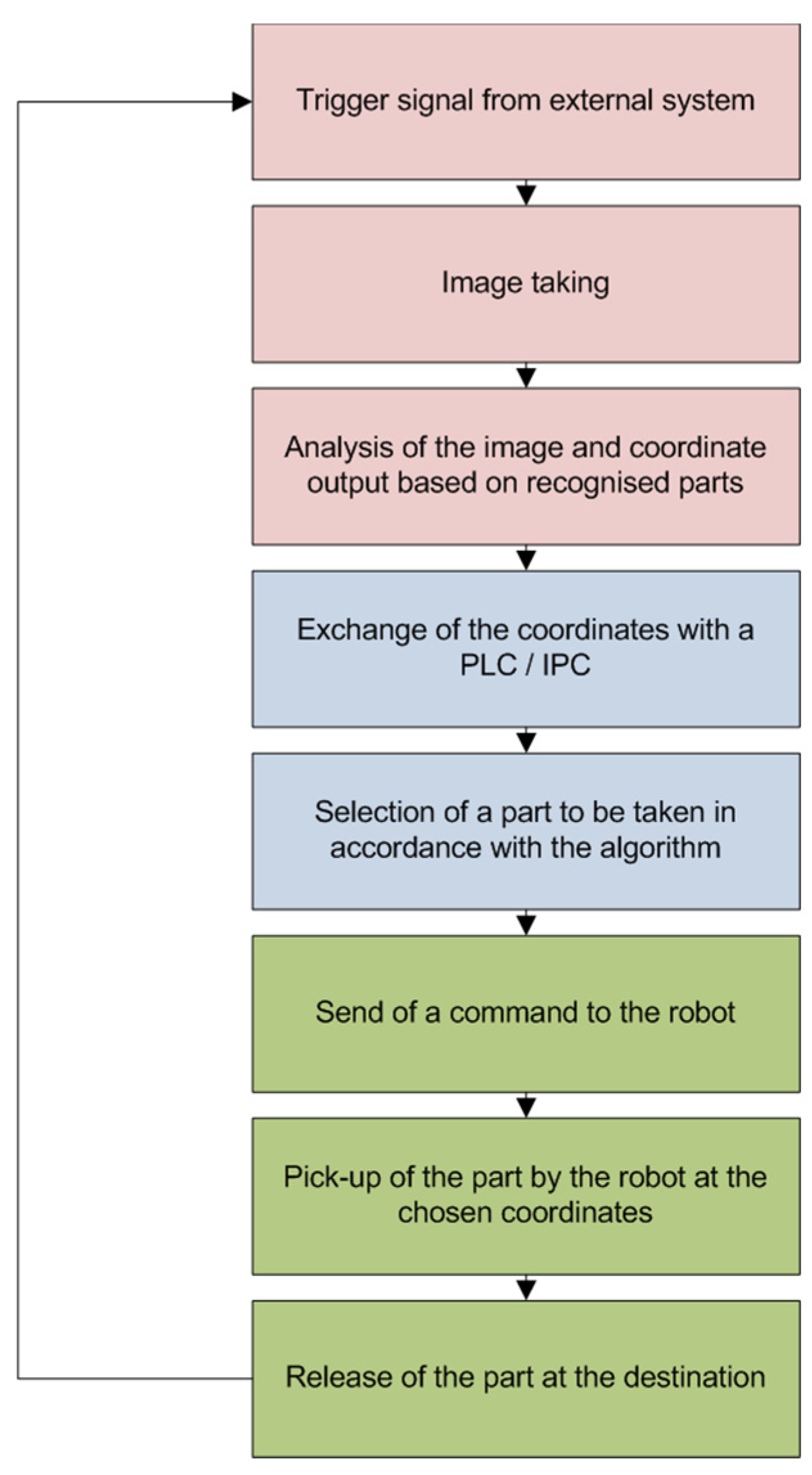
Figure 1 shows a step-by-step algorithm of a generic, flexible feeding system. A project-specific implementation may add or remove some of the stages without serious changes to the general operation. The first stage is to obtain an external trigger signal to initiate the process [
6]. Next, the camera takes an image and starts its analysis. Computing power evolves, and more capabilities exist for fast image processing. Generally, the process is computed by camera hardware and software if it is a vision sensor, or handled by an external software product in the case of PC-based vision systems [
7]. Regardless of the process involved, advanced processing algorithms compare the reference image with the one taken. For flexible feeding, ready tools are used to obtain the coordinates of recognized parts. Usually, with 2D systems, this involves X, Y and an angle of rotation of the part. This is the most frequent case; by contrast, 3D bin picking systems add an additional layer of complexity. Once established, the next step is to transfer the coordinates to a higher control system for further processing. With the processing of this system, the vision system becomes idle until the next image recognition is requested. The control system, by means of an optimization algorithm, decides which is the most appropriate part to be taken (different parameters can be involved, such as distance from the robot, position near edges, or isolation of the part from other parts) [
8]. In fact, robots nowadays are sufficiently fast with standard cycles varying from 0.4 to 0.8 s, so this optimization may not be necessary, and the first part that is received in terms of coordinates may be generally satisfactory with respect to speed and accuracy. Once the part is picked up, it should be delivered to the destination coordinates that are usually identical with every production cycle, but this depends on the layout of the system.
3. Results and Discussion
3.1. Development and Production
The purpose of this development is to build a flexible feeding system that could be reused for many different part geometries [
9]. The frame is based on an Aluminum structural profile system to allow for flexibility and easy future expansion of the system. The camera is installed at a safe distance in order to avoid being hit by the robot. Maintaining the proper focal distance is important to avoid blurred images. A practical camera working distance is 300–1000 mm from the pick-up surface, depending on the choice of lens, resolution, type of camera, and lighting (if any).
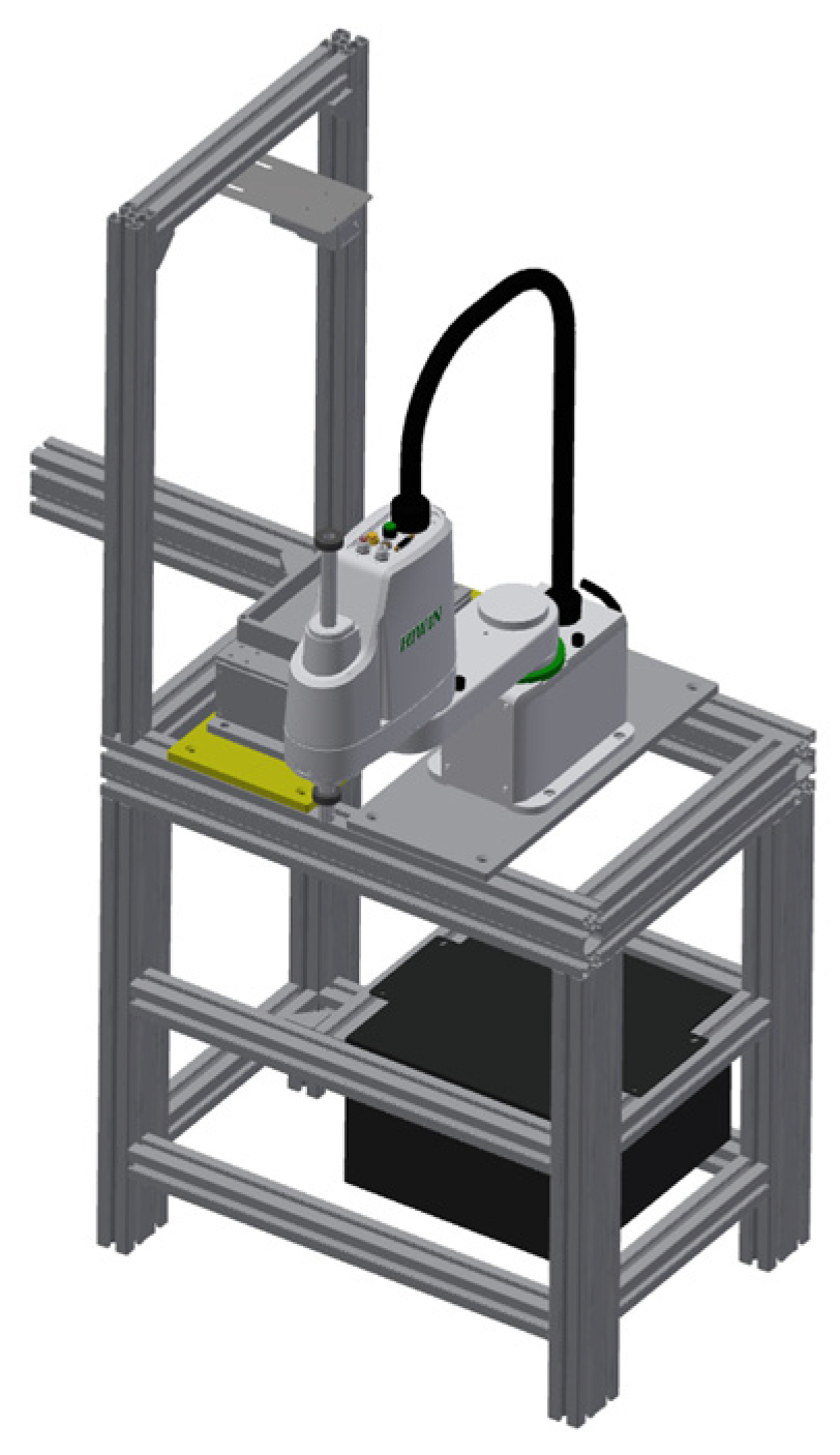
Figure 2 shows a 3D model of the developed system. The design focuses on simplicity, ease of manufacturing, and straightforward integration. Hence, the framework uses an aluminum modular profile system, which can be easily reconfigured or expanded as needed to meet different goals. The system allows for more modules to be attached in a flexible way by means of mechanical and quick electrical connections.
Based on this design, the system is created on a modular principle, allowing for a change in components. For instance, the camera could be different or from another manufacturer. If there is a PLC involved in the system, the type of robot may be encapsulated inside the PLC program, meaning that exchanging robots would also be easy [
10]. This is important if one of the goals is to build a vendor-independent system as much as possible. With today’s challenges, this is sometimes unpredictable regarding suppliers’ lead times, as they tend to face delays, influenced by sporadic problems related to the supply chain management of raw materials.
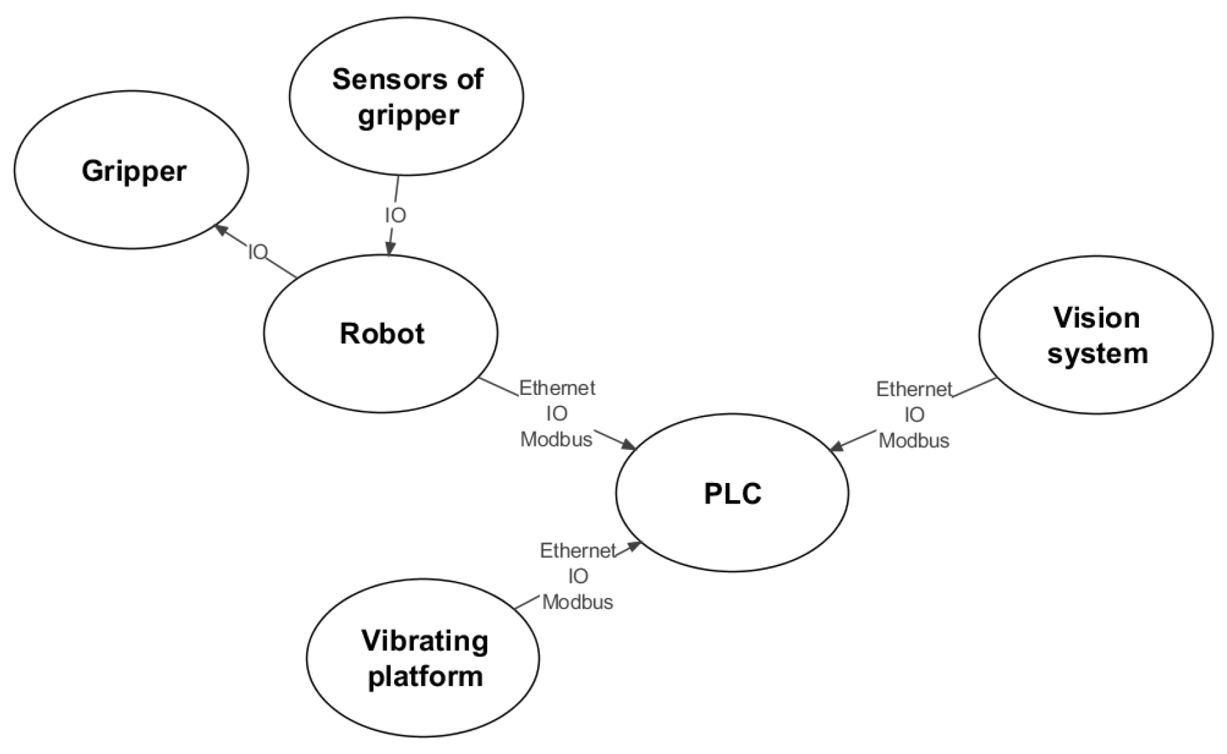
Figure 3 shows the interconnections and relations between the devices in the flexible feeding system.
The proposed operational sequence is as follows: the central role is taken by a PLC, e.g., Siemens S7-1215 or ET200SP CPU 1512, both manufactured by SIEMENS AG, Munich, Germany. They are both powerful enough to handle the task of controlling the other hardware. The PLC is connected to the robot and the camera by means of an Ethernet-based interface, and in the case of Siemens PLC, preferably PROFINET. The PLC could be supplied by a different manufacturer as the system is open to modifications; the algorithms remain the same and should only be redeveloped in the new software environment, using the same programming languages. Over PROFINET communication, the exchange of signals is not limited to physical I/O signals; instead, more sophisticated data could be transferred bi-directionally. Thus, assuming all devices communicate over PROFINET, a common string format could be defined so that coordinates arrive encoded and are decoded inside the PLC and converted to an array of coordinates. The PLC communicates to the robot preferably via PROFINET, or using physical signals, though the latter option is very limited and not recommended as it violates the scalability of the system. Having five inputs and five outputs is sufficient in most projects for controlling robots and is considered one of the simplest options. However, as stated, having an Ethernet-based interface would allow for more advanced communication, with advanced data being exchanged in both directions. The end effector is best connected directly to the robot and controlled via the robot’s own I/O signals. Most industrial robots provide built-in pneumatic/electrical feed-through channels, so integrating the gripper in this manner is straightforward and standard [
11]. The final component is the vibrating plate. Ideally, the vibrating plate should support an Ethernet-based control interface or at least a serial interface such as Modbus. Ordinary I/O signals would still work; however, more IO modules need to be added to the PLC to handle a greater number of I/O signals, and this adds to the project’s costs.
Figure 4 shows the real developed system based on the 3D model. It features a Hiwin RS405-400-200-LU SCARA robot (Taichung, Taiwan), an OC53 camera from IPF Electronic GmbH (Altena, Germany), and a three-axis vibrating device to randomize (separate) the parts based on a predefined vibration algorithm. All devices are connected through the Ethernet-based interface PROFINET. The design deliberately avoids using a PLC since the robot program could handle the coordinate acceptance and communication with the camera and vibration system.
3.2. Experimental Research
The system is capable of working with many different part geometries and shapes. For experimental research, small electronic elements were selected to test this system’s capabilities for working with miniature parts.
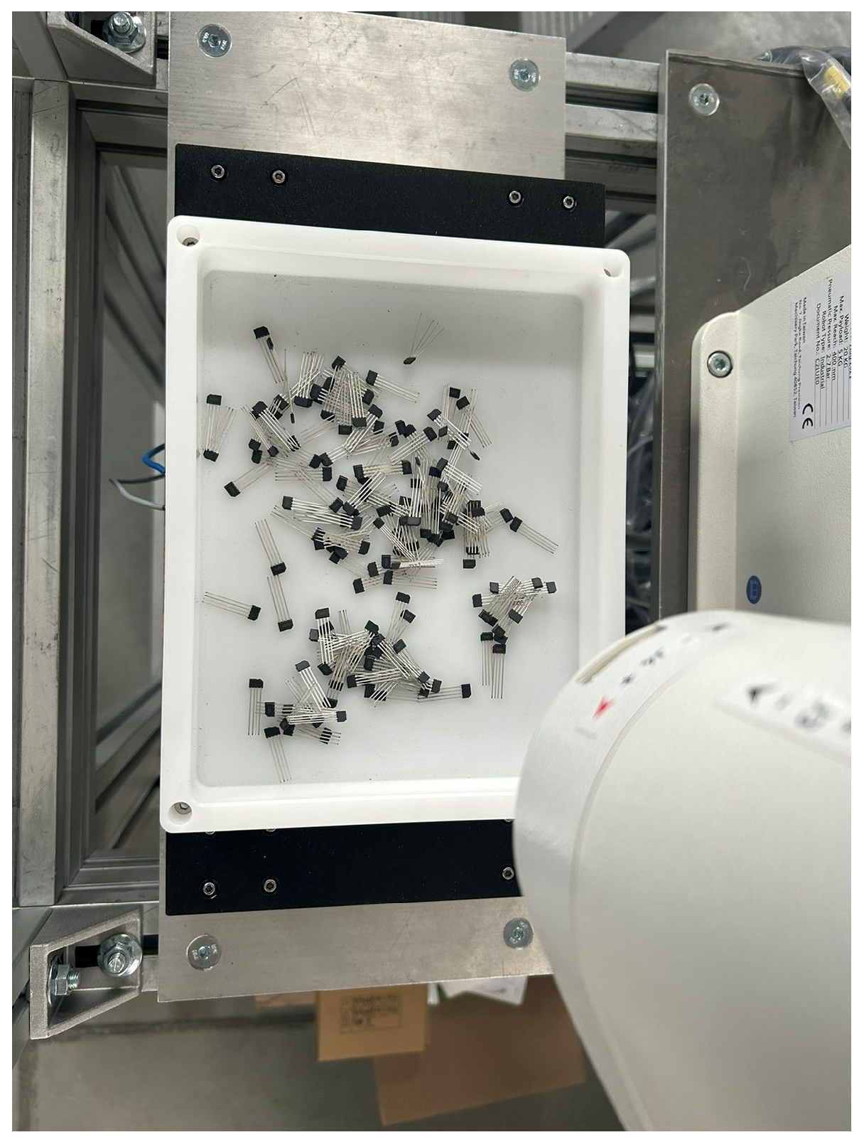
Figure 5 shows the system’s vibrating platform with several sample parts in its bowl. We used a vacuum gripper to pick up these parts in order to avoid physical impact or damage that might occur with a mechanical gripper. These particular parts are extremely delicate, especially at their contact surfaces.
One of the major challenges is to have the camera adjusted for such small parts and avoid errors due to insufficient coordinate precision [
12,
13]. Since the camera also provides an angle of rotation, tolerances are important and need to be reviewed in case they are underestimated at any point.
4. Conclusions
This study presents the development and validation of a flexible part feeding system incorporating robotic manipulation and machine vision technologies. This system addresses the increasing need for adaptable automation solutions in manufacturing environments, characterized by high product variety and frequent changeovers. The experimental results confirm that flexible feeding systems are highly suitable for handling parts with complex geometries and delicate features, offering significant operational advantages compared to conventional mechanical feeders.
Despite the higher initial investment, the flexibility and modularity inherent in the system’s design contribute to a more favorable total cost of ownership over the long term. These design choices (a modular aluminum frame, Ethernet-based communication, and plug-and-play components) ensure that the system can be easily reconfigured or expanded to meet evolving production needs. This openness includes the ability to incorporate components from different suppliers, since the design is vendor-agnostic to a large extent.
The key benefits include a reduced retooling time, minimal maintenance, and the ability to adapt rapidly to new products through simple software reprogramming and gripper modifications. Moreover, the system demonstrates strong potential for supporting low-to-medium-volume production, where traditional feeders would necessitate substantial downtime and tooling changes.
Future work should focus on the development of a form of robot-agnostic platform architecture to enable broader compatibility with different robotic systems by means of ready software plug-in solutions and mechanical adapters. Furthermore, the addition of automated part storage and replenishment modules, as well as integration of downstream processes such as automated packaging, could enhance the system’s autonomy and efficiency. For applications involving larger or heavier components, the implementation of bulk feeding mechanisms would further improve throughput and operational robustness [
14].
In conclusion, the flexible feeding system developed in this study offers a robust, scalable, and future-proof solution for modern manufacturing challenges, supporting the transition toward smart, reconfigurable production environments.


