1. Introduction
Transition surfaces, also known as transition strips or pieces, made from sheet mate-rial, are technical products with diverse engineering and industrial applications. They are most commonly used to connect elements with different diameters, shapes, or sizes, providing a seamless transition between pipes, channels, or structures. These surfaces are typically manufactured from metallic or non-metallic sheet material, such as steel, aluminium, plastic, and other materials, depending on their intended use. Custom production is often required to tailor the shape, size, and material to meet the specific requirements of the project in which they will be incorporated.
The types of transition pieces made from sheet material can be categorised according to several fundamental criteria: shape, function, material, manufacturing method, and application.
Composite transition surfaces from sheet material are used to link elements with different geometric shapes and sizes. They can have circular or oval cross-sections with different dimensions to facilitate the smooth reduction or enlargement of fluid flow passing through them. They may also link elements with rectangular cross-sections, which are prevalent in HVAC (heating, ventilation and air conditioning) systems [
1]. Connecting circular and rectangular sections is an established practice to minimise turbulence in the flow. Additionally, there are transition pieces with intricate geometric shapes, like transitions from elliptical or circular to irregular shapes suited for specialised applications.
According to their type, transition surfaces can be concentric, ensuring uniform fluid flows, or eccentric, commonly applied in horizontal technological lines to prevent fluid retention.
In terms of functionality, composite transition surfaces can act as reducers by decreasing the diameter of channels or pipes in systems with gradually changing fluid flow. They can also function as diffusers by enlarging the diameter of channels or pipes to reduce flow speed and increase pressure. Additionally, composite transition surfaces from sheet material often allow for the connection of multiple lines, such as T-shaped or Y-shaped transitions.
In the production of composite transition surfaces from sheet material, a wide range of sheet metals are extensively utilised relative to the harshness of the environment they will endure and the requirements for durability. The metal transition pieces most frequently employed in industries such as manufacturing and construction should adhere to the rigorous requirements for strength, temperature, and pressure resistance. Therefore, it is recommended that they be made from galvanised steel for its corrosion resistance and suitability for standard ventilation systems; from stainless steel for aggressive environments with high humidity or chemical exposure; from aluminium and aluminium alloys for their light weight and corrosion resistance in low weight systems; as well as from black steel suitable for flue and heating systems [
2].
The creation of developments of composite transition surfaces from sheet material typically entails the use of CAD software (version 2024.1.6). One of the most widely recognised software products is AutoCAD, suitable for generating 2D drawings and simple developments. Its inherent compatibility with other engineering programmes makes it particularly advantageous for this purpose. Other programmes that can be used to construct developments include SolidWorks, Inventor (Autodesk), CATIA, and others [
3].
During the manufacturing process of composite transition surfaces, the sheet material undergoes initial cutting through methods such as laser or plasma cutting, and in certain instances stamping may also be implemented [
4,
5]. Bending, subsequently, occurs at pre-determined locations, followed by the joining of individual bent paths through welding, riveting, or hinge connections.
2. Materials and Methods
In the construction of a development of a composite transition surface, each wall of the transition piece is sequentially applied in a single plane. It is essential that each wall is projected at its actual size, and the order in which the walls are applied plays a vital role in the development process. Creating a development of a composite transition surface re-quires close adherence to two principal rules:
The first requirement for accurately determining the actual size of every wall implies the selection of an appropriate method to ascertain the true size of every single edge on the transition surface.
A variety of methods can be applied to calculate the true size of every edge on the transition surface, ultimately providing an accurate description of the true size of every wall within that space.
The first method that could be used to determine the true length of a desired edge is transformation (
Figure 1a). The transformation method involves the introduction of an additional projection plane that runs parallel to or aligns with the targeted edge. In the drawing shown in
Figure 1, the trace of the additional (third) projection plane coincides with the sought segment B
1A
1. The distance between the targeted segment and the trace of the additional, auxiliary projection plane does not affect the final solution. Perpendiculars are dropped from each point of the segment AB to the new projection plane, and the ordinates of each point are applied from the horizontal projection (represented in magenta in the drawing in
Figure 1a). Connecting points A
3 and B
3 results in the segment A
3B
3, which is the true size of the segment AB [
6].
The second method, as displayed in
Figure 1b, involves rotating a line around an axis. The idea is to take a segment that is in a general position where it does not project at its true size in any of the principal projection planes and rotate it to a position where it becomes parallel to a principal projection plane, allowing it to be projected at its true size. In this case, the axis around which the segment rotates is conveniently positioned to intersect one of the points on the line. In the example depicted in
Figure 1b, the axis of rotation is chosen to pass through point B. To find the desired rotated position of the line, it is necessary to rotate point A, which is different from the point through which the axis of rotation passes, to the desired position; that is, until the line AB becomes parallel to the x-axis and consequently to the frontal projection plane. The actual true size of this segment is projected in the adjacent projection, denoted in this case as
B1.
The experiment illustrated in
Figure 1 demonstrates the equivalence of the two methods, both yielding identical end results.
Additionally, there exists a third method for determining the true size of the edges of the transition surface, which is analytical rather than constructive.
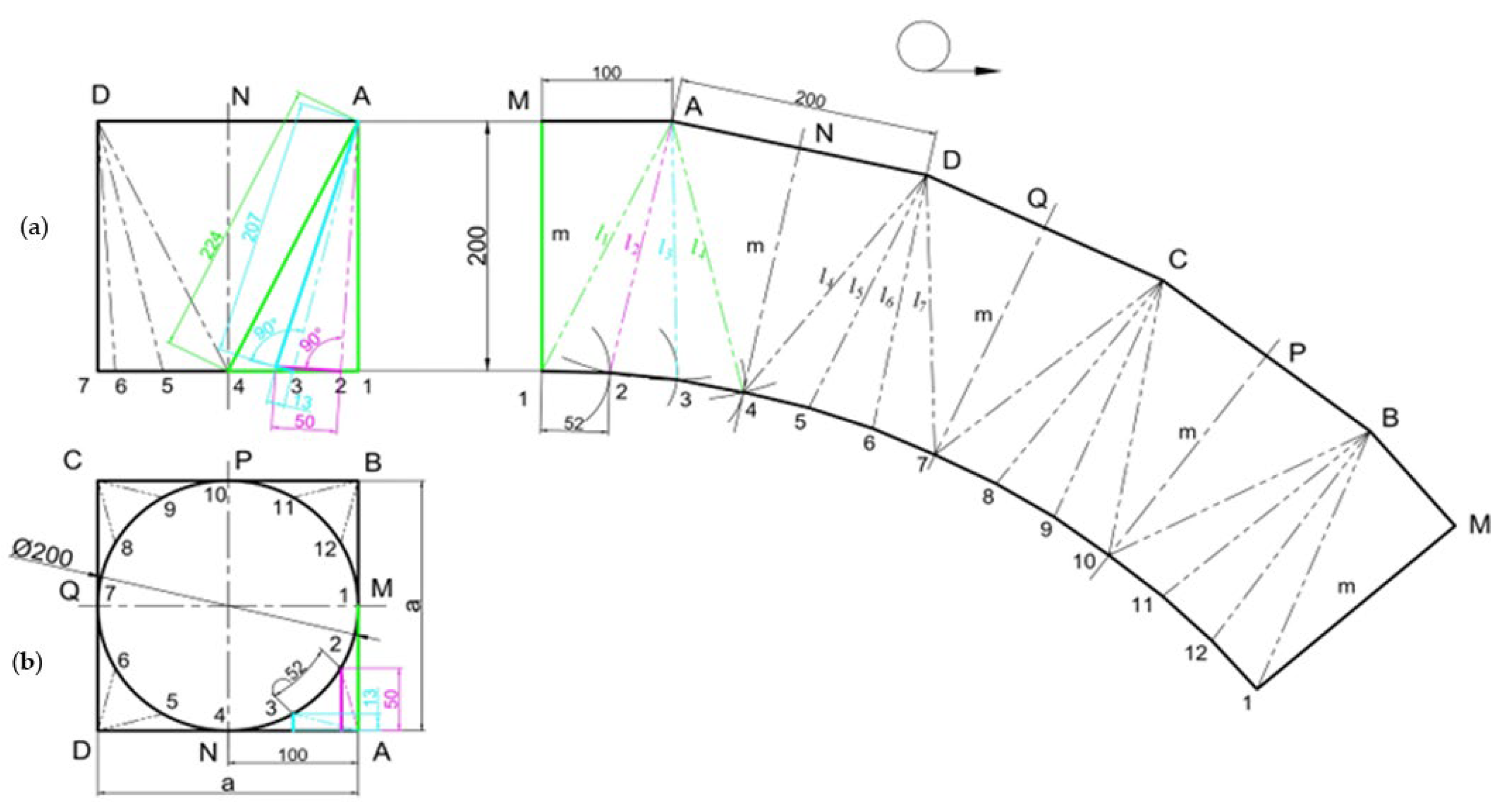
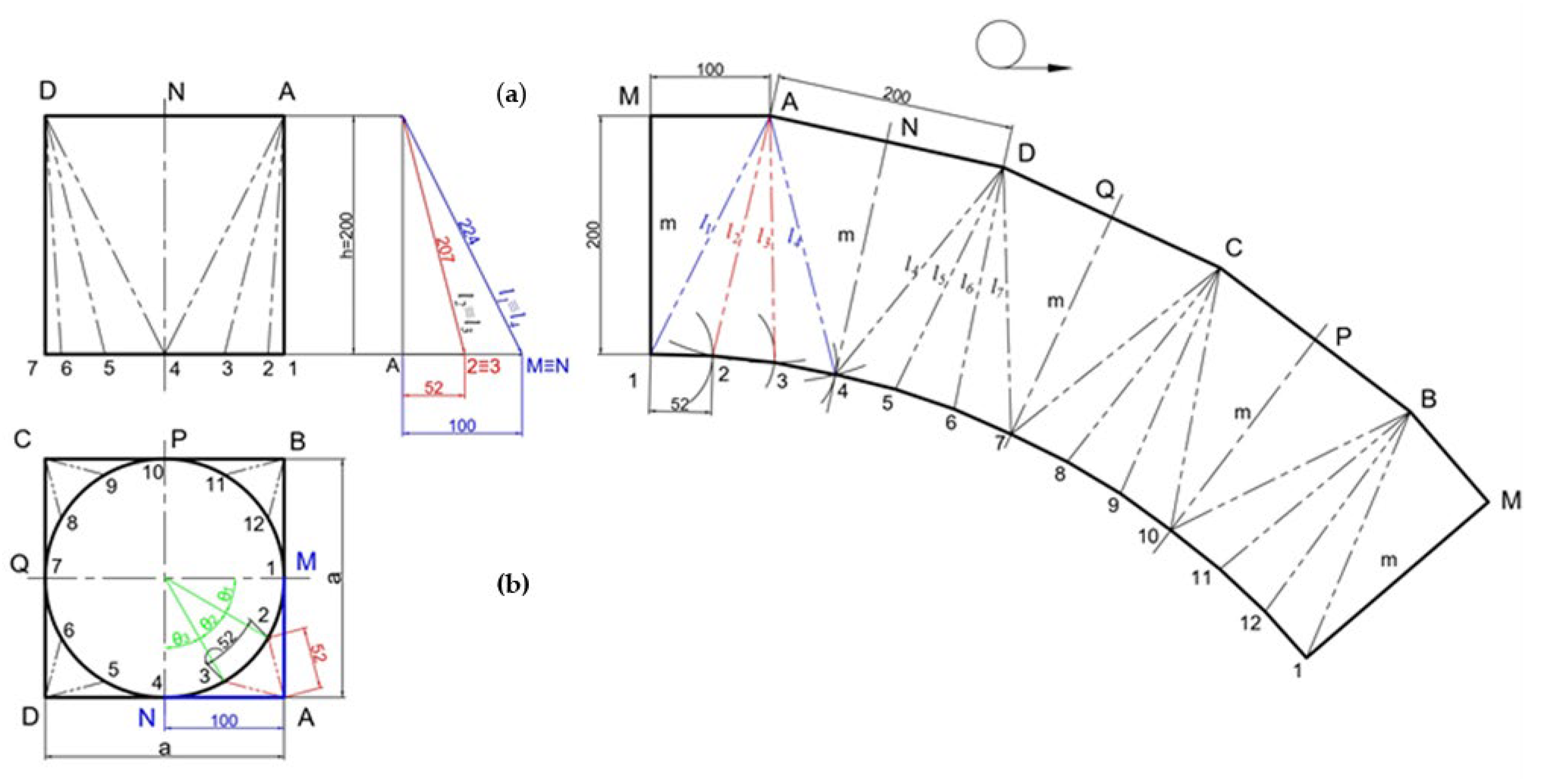
Let us explore various cases of projecting composite transition surfaces, starting with a straightforward case where the surface transitions from a square to a circular cross-section and the diameter of the circular cross-section D aligns with the dimensions of the square cross-section a, or D = a. The solutions to such a problem using both methods are outlined in
Figure 2 and
Figure 3, revealing that both methods for determining the true size of each of the edges, transformation and rotation, yield completely identical values.
Once the true size of each edge is determined, the subsequent step that is equally important for producing an accurate development of the composite transition surface is strict adherence to the order of applying each edge and determining the true size of each wall on the drawing sheet. Drawn sequentially with a compass is the following: one arc with a length equal to the edge in true size, and another one with a length equal to the corresponding segment of the circumference divided into 360/2
n parts. The intersection points of the two arcs connecting to the starting points construct each wall of the transition surface. As each individual flat triangle is added sequentially, they come together to create the surrounding surface of the composite transition. The completed developments of the composite transition surfaces can be seen in
Figure 1 and
Figure 2 and are marked with the symbol for development: a circle combined with a short arrow.
The edges of the transition surface can also be determined analytically using the following dependencies:
Given that the medians of the triangles A1B, A4D, D7C, and C10B are equal to the height of the transition, from the initial condition, that the diameter of the circular cross-section coincides with the dimensions of the square cross-section, it follows that
h =
m [
7], wherefrom the length of each edge can be calculated as the following:
where
k is the serial number of the point on the circumference of the transition surface; 2
n is the number of divisions of the circumference;
θk is the changes within the range of 0 to 360°;
ε is the central angle corresponding to one division of the circumference of the transition piece;
m is the median and
h is the height.
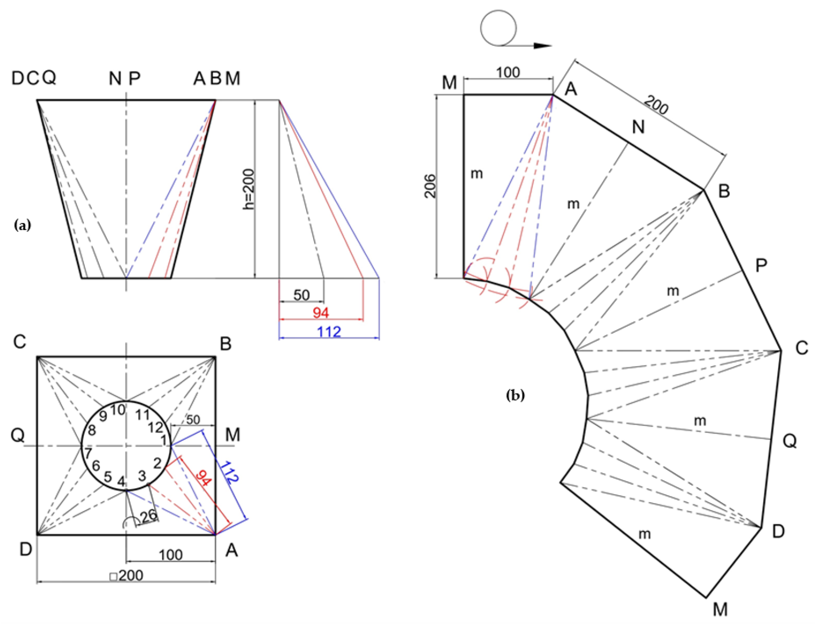
In cases where the square cross-section exceeds the circle’s diameter or
D < a, the drawing of the composite transition surface will take on the form depicted in
Figure 4.
3. Results and Discussion
The analytical relationship for this type of transition surfaces assumes a different form, as the median of the triangle formed at each square base is no longer representative of the height of the composite transition surface, hence the following:
Figure 5 illustrates a case where the diameter of the circular cross-section aligns with one dimension of the rectangular cross-section, in particular
a =
D and
b >
D.
Figure 6 illustrates a case where the sides of the rectangle surpass the diameter of the circular cross-section (
a > D and
b > D).
The development of the transition from a circular to a rectangular cross-section in a typical scenario is demonstrated in
Figure 7. The elements display the following analytical relationships.
For the generator
θk from 0 to 90°,
For the generator
θk from 90° to 180°,
For the generator
θk from 180° to 270°,
For the generator
θk from 270° to 360°,
The developments of composite transition surfaces where the transition is from standard regular cross-sections to cross-sections of complex composite shapes are also of particular interest. Such a problem is discussed in
Figure 8. In similar cases, a more creative approach is required to solve the problem. Due to the irregular shape of one of the cross-sections, the circular cross-section is not divided into 2
n equal parts. In the complex cross-section exemplified in
Figure 8, there is an acute angle, an obtuse angle, an arc of a circle, and rounding of one of the angles. With the diverse array of shapes present on a transition surface, each of these segments requires a specific approach in order to correctly determine the true size of each of the edges on the surface.
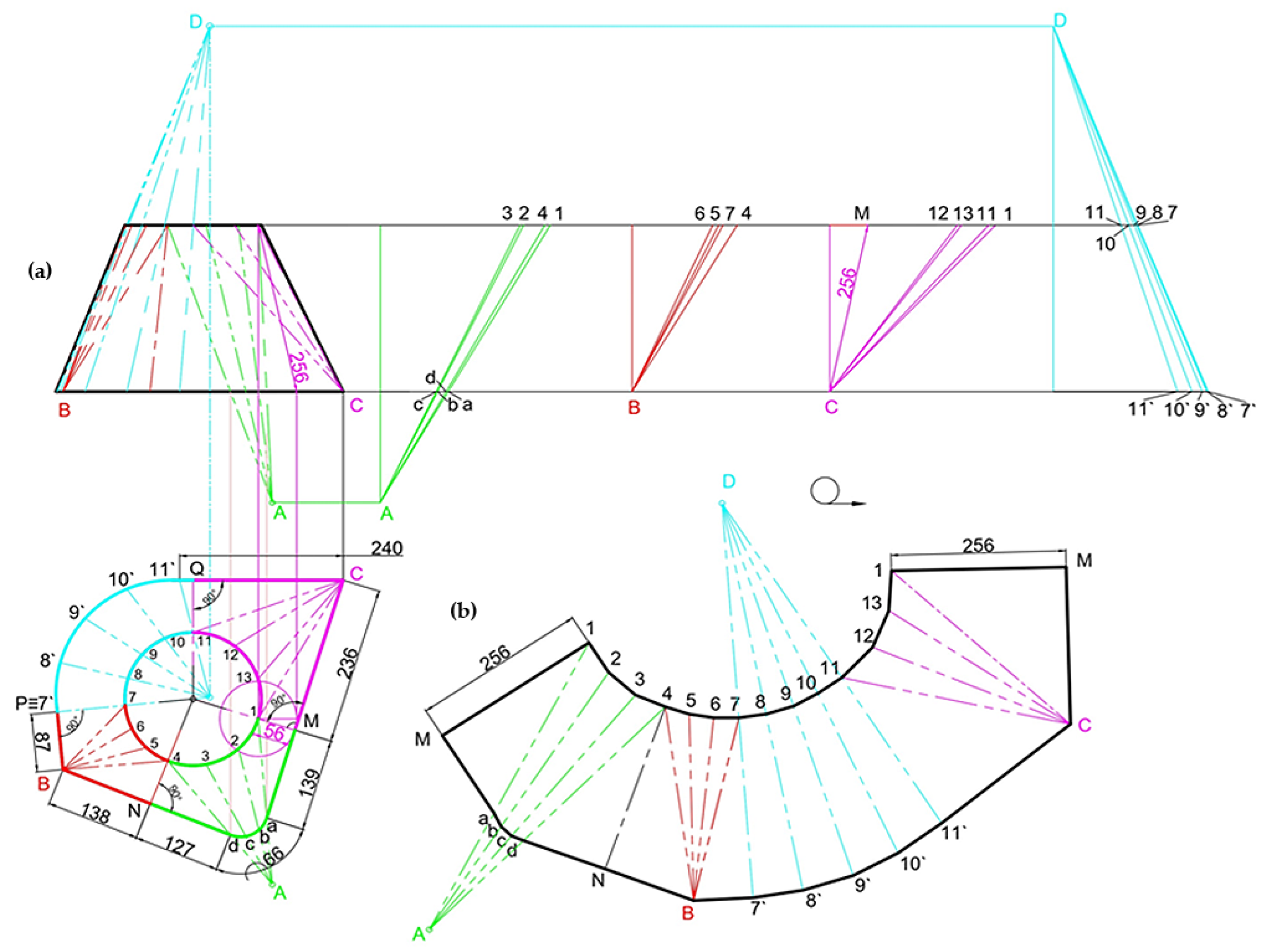
Initially, the irregular shape at the base of the transition surface (the horizontal projection in
Figure 8) is divided into its four component shapes. This allows for individual solutions to be adopted for the composite transition surface. The division occurs with the centre of the circular cross-section serving as the focal point for the four sectors, from which perpendiculars are dropped to each side of the irregular base. This method facilitates the distinction between the four different constituent shapes, visually represented in
Figure 8 by different colours. Subsequently, a solution is prescribed for each of them.
- -
The first sector, defined by the points MAN (shown in green in the drawing in
Figure 8), has a rounding at point A with a radius of 40 mm. The resulting arc, with a length of 66 mm, is divided into three equal parts between the points a-b-c-d. The corresponding sector of the circular cross-section of the transition surface is also divided into three parts between the points 1-2-3-4. Straight lines are drawn between the points 1-a, 2-b, 3-c, and 3-d, with all these lines intersecting at point A. This sector concludes at the medians 1M and 4N.
- -
The second sector is shaped at the obtuse angle B, with straight lines dropped to the sector of the circular cross-section of the transition surface, divided again into three parts. This is represented in red in the drawing in
Figure 8.
- -
In the circular sector, depicted in cyan in
Figure 8, the arc is divided into equal parts at the irregular base and at the circular cross-section. Straight lines are dropped through the resulting points, all intersecting at the single point D.
The final fourth sector, highlighted in magenta on the diagram, is formed at the acute angle C, and straight lines, which will define the future edges of the composite transition surface, are extended from there towards the circular cross-section, which, in this sector, is split into three parts.
An interesting aspect of this intricate composite transition surface is that two of the points where the edges of the surface intersect are located outside the boundaries of the transition surface. This particular solution was not encountered in the previously examined cases.
The problem is solved using the rotation method, where the true size of each of the edges is determined in projection relation to the frontal projection of the transition surface. Points A and D in projection relation to the projection, and the true size of each of the edges, is defined between the two lines that outline the height of the transition surface.
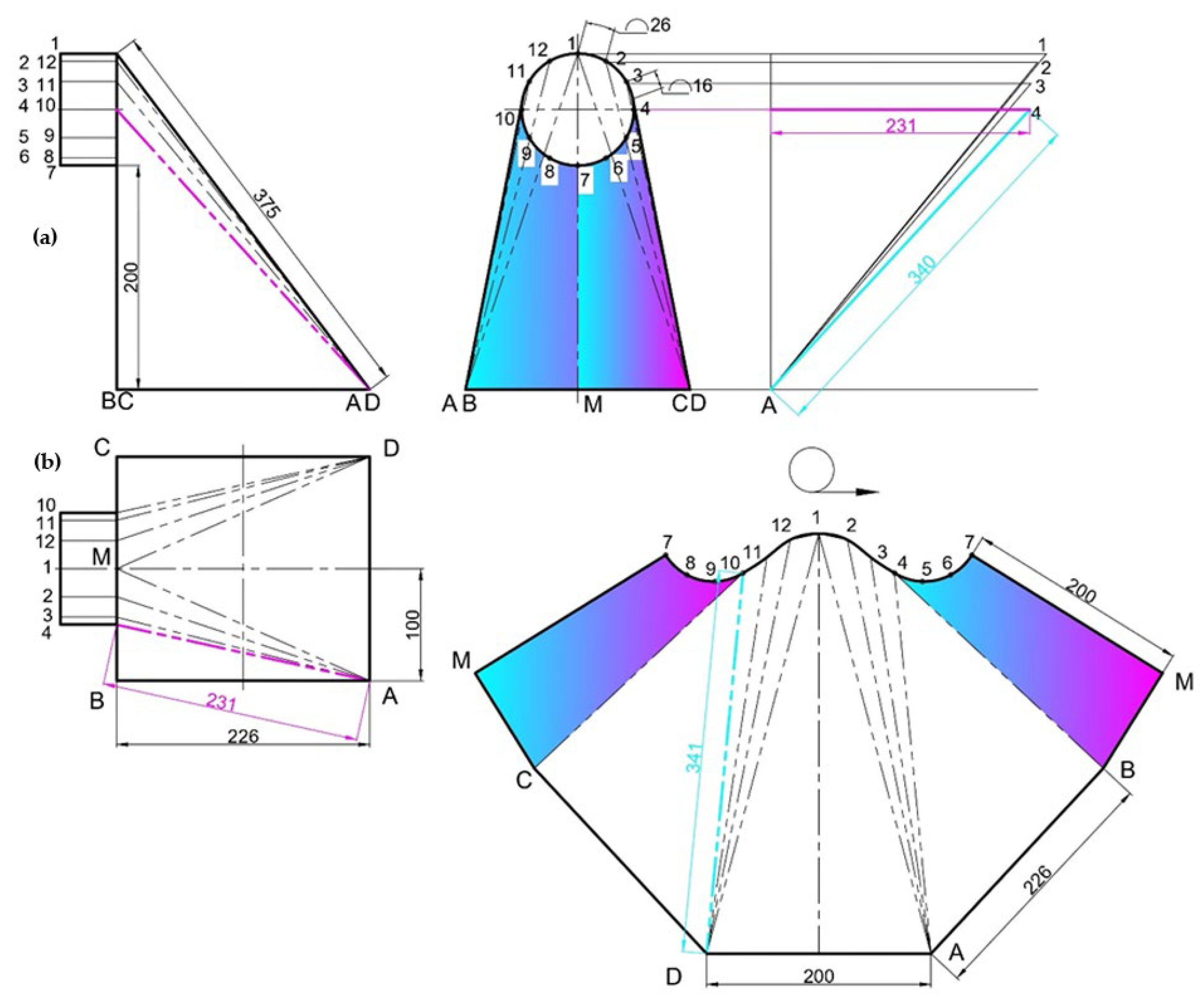
Another interesting case is the construction of a composite transition surface between two mutually perpendicular surfaces.
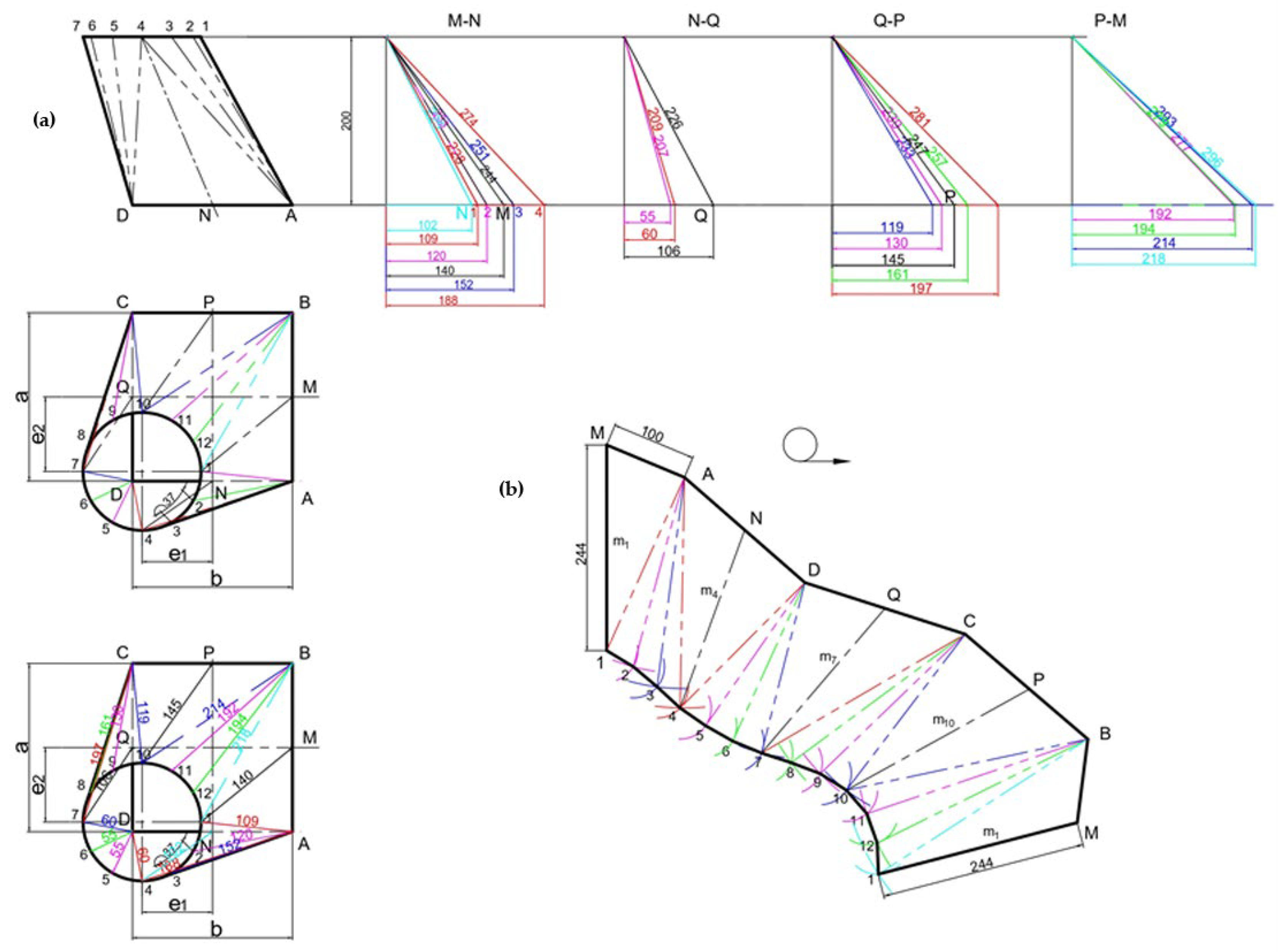
Figure 9 illustrates a case where the transition changes from a prismatic to a cylindrical surface, with the axes of the two surfaces no longer being collinear, as seen in the previously reviewed cases.
The solution to the problem begins by dividing the circular section of the cylindrical surface into 12 equal parts. The circular section is further divided into four quadrants, with the points from each quadrant being connected to one of their respective four corners on the rectangular section. The points located above the horizontal axis on the circular section of the transition surface 10-11-12-1 are connected to point D on the rectangular base of the surface, while the points 1-2-3-4 are connected to point A. This delineates the locations of the edges of the transition surface in the drawing with a dashed line marked with two dots. The transition surface, depicted in
Figure 9, shows two symmetrical segments at points 7-8-9-10-C-M and 4-5-6-7-M-B, marked in cyan and magenta, which are projected in the profile projection with their true size and shape due to their specific position. In
Figure 9, the surface is presented in its three projections, along with the development of the composite transition surface.
The true size of the edges is then ascertained by taking the length of each edge from the horizontal projection and transferring it to the profile projection against its corresponding point (see the example marked in magenta in the drawing). The resulting point is then connected to point A at the base to find the true length of each edge. The true size ascertained for each edge is utilised to construct the development of the composite transition surface.
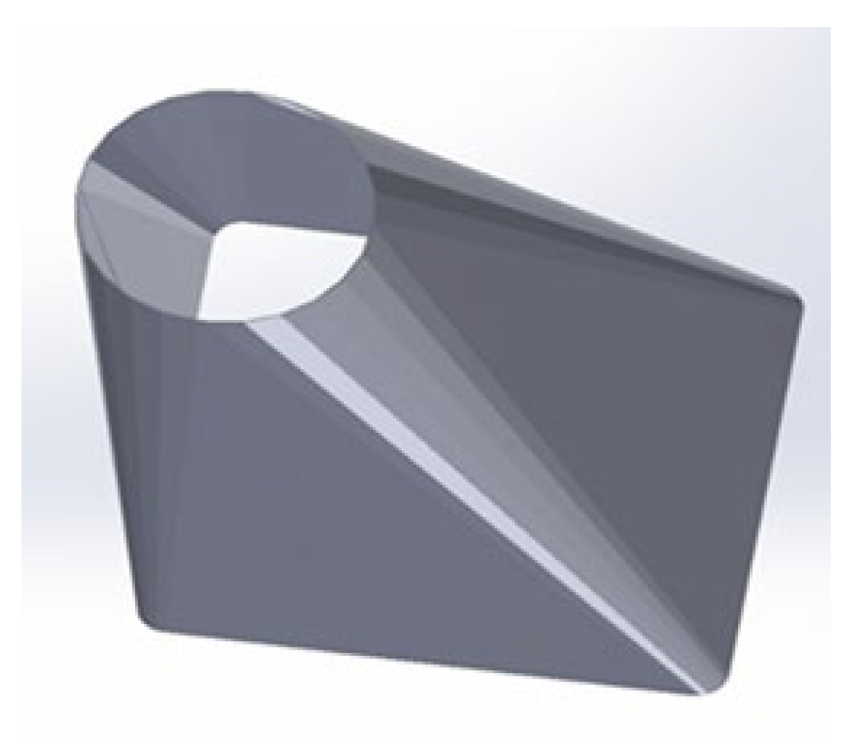
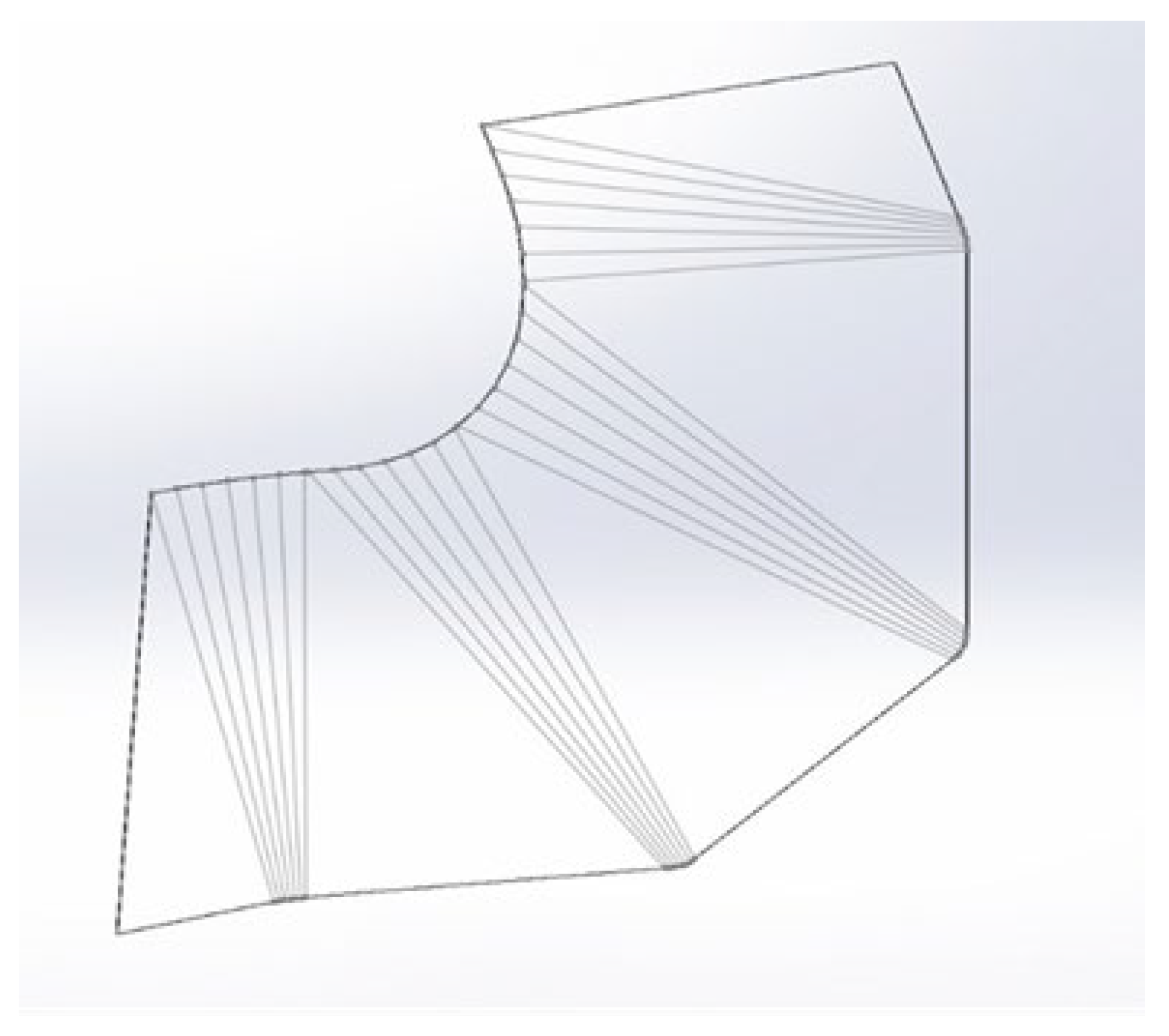
The process of creating composite transition surfaces from sheet material in modern engineering can also be accomplished through the use of digital twins. CAD software, such as SolidWorks, Invertor, CATIA, and other tools, are commonly employed when creating developments. This approach allows for the composite transition surface to be projected in three dimensions, with the programme requiring the specification of the sheet material thickness. Through a series of steps, the software automatically unfolds the constructed surface, as detailed in
Figure 10 and
Figure 11, which displays a similar transition surface designed via SolidWorks CAD software [
9,
10,
11].
The utilisation of CAD software in the construction and design of composite transition surfaces enables engineers to virtually test different designs, providing insights into how the material will behave in the intended form, which can save time and resources compared to physical prototypes. The already designed composite transition surfaces can also be used in simulations for stress analysis, thermal properties, along with others [
2,
11].
The methods applied for visualising and analysing 3D objects in 2D space, as utilised in descriptive geometry, play a critical role in accurately defining the construction and modelling of composite transition surfaces between diverse geometries.
Geometric modelling of developments is a critical stage in the design of sheet metal objects, serving as the meeting point between theoretical geometry and applied engineering sciences. The challenges encountered stem from the limitations of mathematical models in accurately representing real materials and technologies. The key to success lies in taking a multidisciplinary approach when designing composite transition surfaces. One of the primary challenges specifically related to geometric modelling is dealing with doubly curved surfaces that cannot be accurately unfolded into 2D space due to non-zero Gaussian curvature [
11]. Additionally, designing transition surfaces involves not only unfolding a 3D object, but also predicting deformations during the reverse moulding process of a 2D template into a 3D object, as the elastic properties of the material alter its final shape after assembly [
12].
Issues related to the use of digital twins are often linked to software limitations and unfolding algorithms. Most CAD systems, such as SolidWorks and CATIA, rely on simplified mathematical models that do not account for nonlinear deformations. This can be problematic as software tools may still have difficulty accurately capturing localised shrinkage or stretching, despite the capability to specify material thickness during surface modelling.

