1. Introduction
Paper [
1] describes an industrial operation emulator that operates with the Siemens S7-1200 programmable logic controller, developed using the LabVIEW programming environment. This emulation system encompasses dual manufacturing operations: a blending unit and a fluid level regulation mechanism.
The hands-on development [
2] of automated systems controlled by programmable logic controllers represents a commonly acknowledged obstacle. This research presents a manufacturing process modeling application designed for Microsoft Windows platforms, functioning with various programmable automation controller types. The operation configuration interface provides comprehensive capabilities while maintaining ease of use. A cost-effective hardware bridge connects the computer’s communication port with the controller’s digital and analog input/output channels.
In paper [
3], a tool for simulation of automation and process control is proposed, which can simulate a programmable logic controller (PLC) programmed in the structured text language using multitasking. The simulator can be used to verify dynamic processes and controllers for discrete-event, discrete-time, and mixed systems.
Paper [
4] describes the problem of visual programming of programmable logic controller (PLC) devices. A demonstration programming method has been developed that allows specialists in the relevant field to program such devices without the need for computer programming skills. The method is innovative because, unlike other demonstration programming methods, it requires minimal prior knowledge of the controlled system model and does not require interaction with a real system.
Reference [
5] outlines the functionalities of a programmable logic controller educational emulator and presents several software demonstrations intended for instructing fundamental automation programming concepts. An experiential learning methodology is suggested to enable learners to acquire knowledge progressively, which is anticipated to produce lasting educational outcomes.
Paper [
6] describes the creation and application of the CQMIH programmable controller emulator, which employs the OMRON Host-Link communication standard through an RS-232 interface connection and operates with both analog and digital input/output channels. The objective of this emulation tool is to streamline code troubleshooting procedures during communication software development.
Research [
7] presents the construction of a virtual emulation environment for visual verification of automation control algorithms. ROBOWORKS and IGRIP platforms were utilized for the three-dimensional modeling framework. Integration utilities were created to facilitate seamless connection between the proposed emulators and 3D visualization systems along with software-based controllers. The framework was tested on actual automation applications, demonstrating that control programs can be effectively verified through this methodology.
Power line communication is becoming fundamental for smart home and network applications [
8]. This technological approach persistently exhibits its potential and benefits. Enhancing its functionality within residential networking environments necessitates network structure assessment and signal propagation modeling methodologies. The emulation system derives the mathematical relationship between two designated connection points. The emulator employs a multi-route framework to establish this mathematical relationship.
Publication [
9] concentrates on the mechanization of manufacturing operations utilizing diverse instruments, including programmable controllers, LabVIEW platforms, and web connectivity. Within the suggested framework, the programmable logic control approach is executed through FATEK PLC hardware. The intended industrial mechanization solution is accomplished by deploying a real-time supervision and monitoring infrastructure that interfaces with the FATEK programmable controller and LabVIEW data collection software.
2. Purpose of Development
2.1. Industrial Process
The management of industrial processes requires that they be built from control systems—industrial controllers, data acquisitions and control systems—SCADA and/or HMI displays (
Figure 1).
In the development of SCADA and HMI, the process is mainly divided into two parts:
For the purpose of evaluating the software before its implementation in industrial processes, the presence of a physical controller is required. This is necessary, since the operation of these systems is directly dependent on reading the current state of the desired resources in the controller. If there is no physical industrial controller in the design process, it is impossible to test SCADA and HMI.
The purpose of this development is to design a controller simulator, the main purpose of which is to send and receive messages according to the appropriate communication protocol. This solution will allow SCADA and HMI to be connected to such a simulator and to be tested with all possible resource data. The development presents a simulator based on FATEK industrial controllers, implementing the FACON communication protocol. To test the operation of the simulator, a test program was used that sends and receives messages to/from the simulator and visualizes the data at the communication and application level.
The FACON protocol is implemented in the developed simulator. The implementation is based on the detailed description of the messages in the protocol documentation [
10].
2.2. Facon Protocol
The message format of the FACON protocol [
10] is presented in
Figure 2.
Each message consists of the following six fields:
Start code (STX)—that is code 0x02 from the ASCII table.
Slave station No.—two bytes of slave station number in HEX format in a range of 1–255. 0 means all slave devices will receive a message.
Command code—two bytes for a command code. The FACON protocol consists of 14 commands described in detail in a FACON datasheet [
10].
Data—consists 0–500 bytes depending on command type.
Checksum—two bytes for CRC sum, called LRC (Longitudinal Redundancy Check). It is calculated by adding all bytes from fields 1 to 4.
End code (ETX)—that is, code 0x03 from the ASCII table.
3. Developed Simulator
3.1. Overview
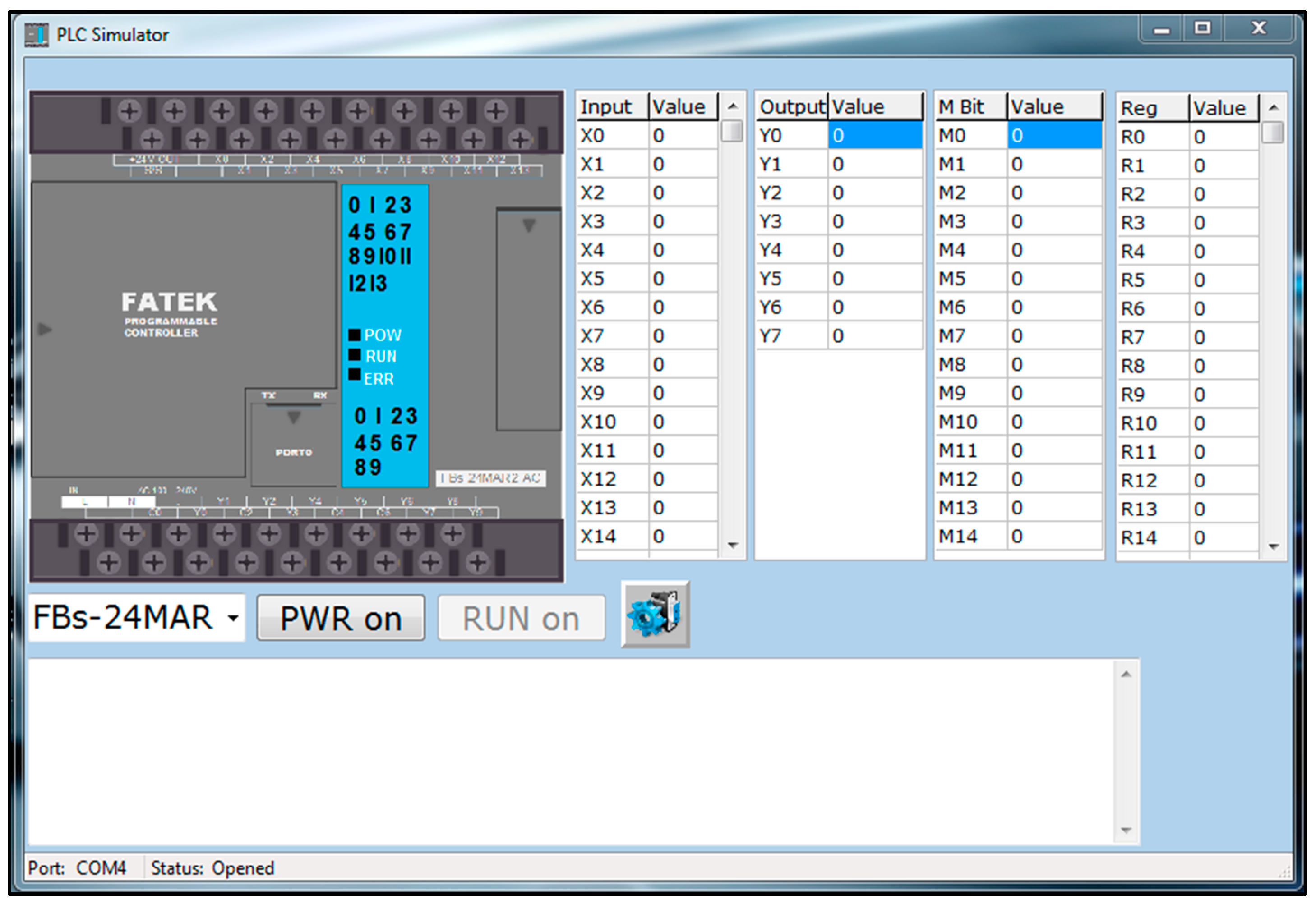
Figure 3 displays the primary interface of the emulation system.
It consists of the following:
A graphic image of the selected PLC.
Buttons to simulate the power and start mode of the PLC.
Tables with data on general resources.
A log field for sent and received messages.
Options to configure the COM port according to the requirements of the specific application.
3.2. Class Communication
Figure 4 shows the communication between the classes implemented at the application level. The communication is asynchronous and is performed through “events”. In this way, the simulator does not block, the interface does not freeze, and the user can work with the graphical components.
Two classes for message processing are implemented in the developed simulator, and one class for GUI controls:
faconPLC—processes messages at the channel level. It works in two modes:
receive mode message—receives all bytes from COM port and after checking for correctness sends to the class fatekPLC
sending mode message—sends a message after a request from fatekPLC, formats the corresponding message according to the format, and sends it via a serial interface.
fatekPLC—processes messages at the application level. It works in two modes:
receive mode message—receives the message from faconPLC and decodes it at the application level, on individual fields. Depending on the type of message, it sends a signal to the main program for data visualization, etc.
Sending message mode—receives a signal from the main program to send data. Forms the corresponding data for the fields of the message being sent and transmits them to faconPLC.
MainWindow—Receives data from fatekPLC and updates GUI control values, provides the ability to write data for controller resources directly from table controls, and simulates operating modes of PLC—POWER and RUN.
3.3. Algorithms
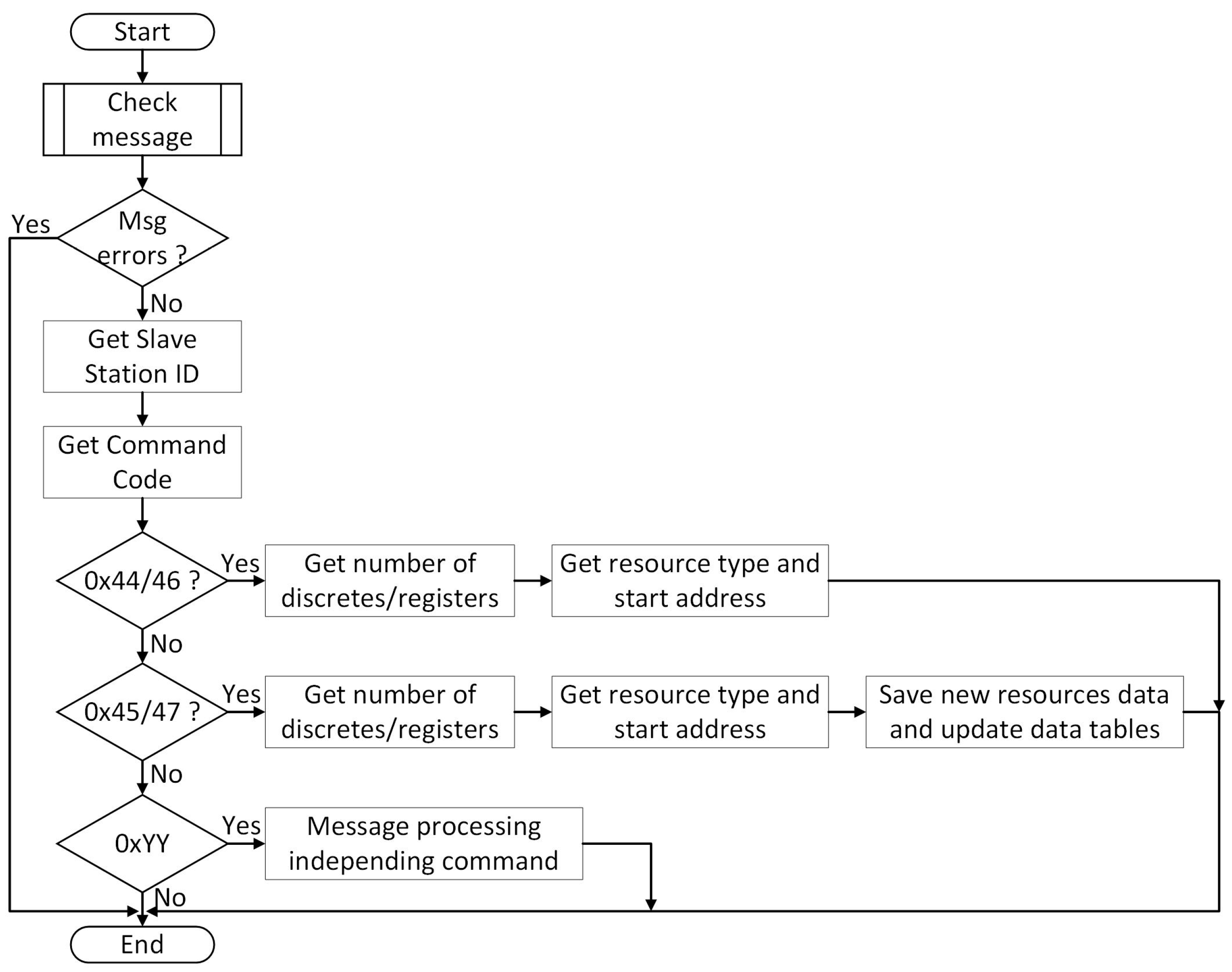
Figure 5 shows the basic flowchart of the main functional procedure of the developed simulator.
Figure 6 shows the basic block diagram of the message processing sub-algorithm.
The simulator offers operation in both modes—POWER and RUN, just like the real controller. If it is powered and started (RUN mode is on), messages can be received.
Figure 6 shows the algorithm for processing a received message. The part with the commands that are more important for development is shown in detail—0x44, 46, 45, and 47, which are related to reading/writing resources from/to the controller. Some of the message fields are common to all commands and are processed generally. Then, depending on the command number, each message is processed independently, since it consists of specific commands.
4. Experimental Setup
The testing configuration comprises the following elements.
The constructed emulation system (
Figure 3). The emulator is created within the C++ Builder development environment utilizing C++ programming syntax.
Developed software test program (
Figure 7). This program sends and receives messages to/from the developed simulator. This test program simulates a simple SCADA system that sends and receives data from the controller/simulator.
A workstation containing both software programs for conducting the testing procedures.
Two USB to RS232 adapters (Elimex, Guangzhou, China) that create virtual serial communication ports for RS-232 protocol connectivity. Each software program must operate through a distinct serial port since they share the same physical hardware platform.
Bidirectional communication cable equipped with DB9 terminals. For testing purposes, it is adequate to link only the transmit and receive lines of both adapters to establish bidirectional data exchange. During testing operations, the serial port configurations must remain identical.
The test program provides the option for manual testing of the simulator. The Read and Write buttons send messages to the developed simulator and receive data from it.
5. Experimental Results
To test the simulator’s performance, four of the possible messages from the FACON protocol have been selected—0x44, 0x45, 0x46, and 0x47.
To establish correct communication and the correctness of the messages, several template messages from the FACON protocol documentation are used. If they are sent and received in the same format, this guarantees that the messages are formed correctly according to the standard. In one of the tests shown, a created sample command is sent, which is not described in the documentation, in order to demonstrate the correct operation of the simulator.
Reading discrete type resources—0x44 Read multiple statuses of consecutive discrete elements. During this examination, a communication is transmitted to read digital input resources X50–X55, a total of six inputs, using a template message [
10] shown in
Figure 8—command 0x44.
Figure 9 and
Figure 10 show the screens with the settings of the two programs and the messages that are transmitted between them.
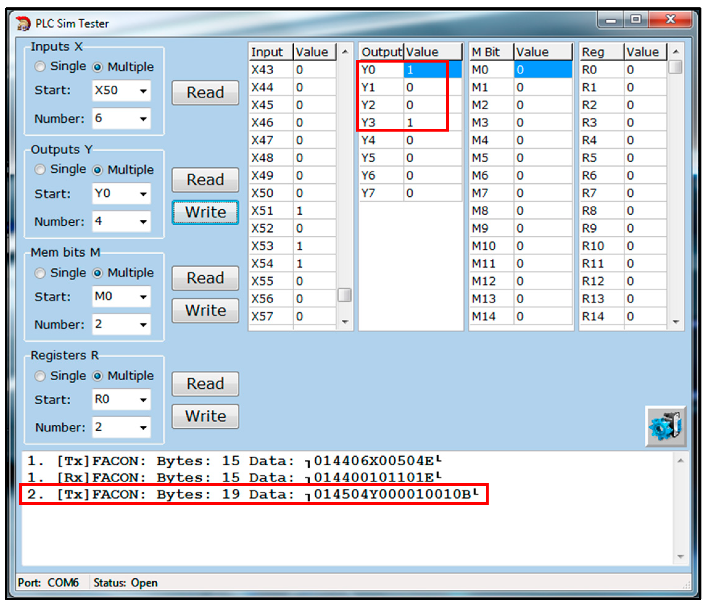
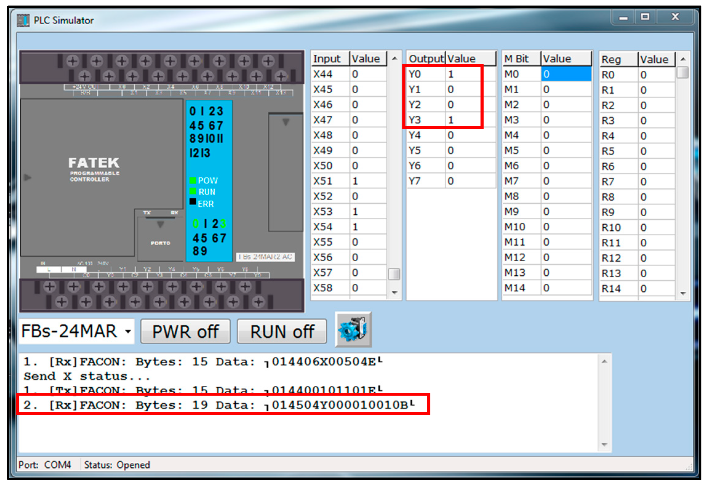
Writing of discrete type resources—0x45: Write multiple statuses of consecutive discrete elements. In this test, a message is sent data for discrete resources Y0–Y3, a total of four outputs using the template message [
10] shown in
Figure 11—command 0x45.
Figure 12 and
Figure 13 show the screens with the settings of the two programs and the messages that are transmitted between them.
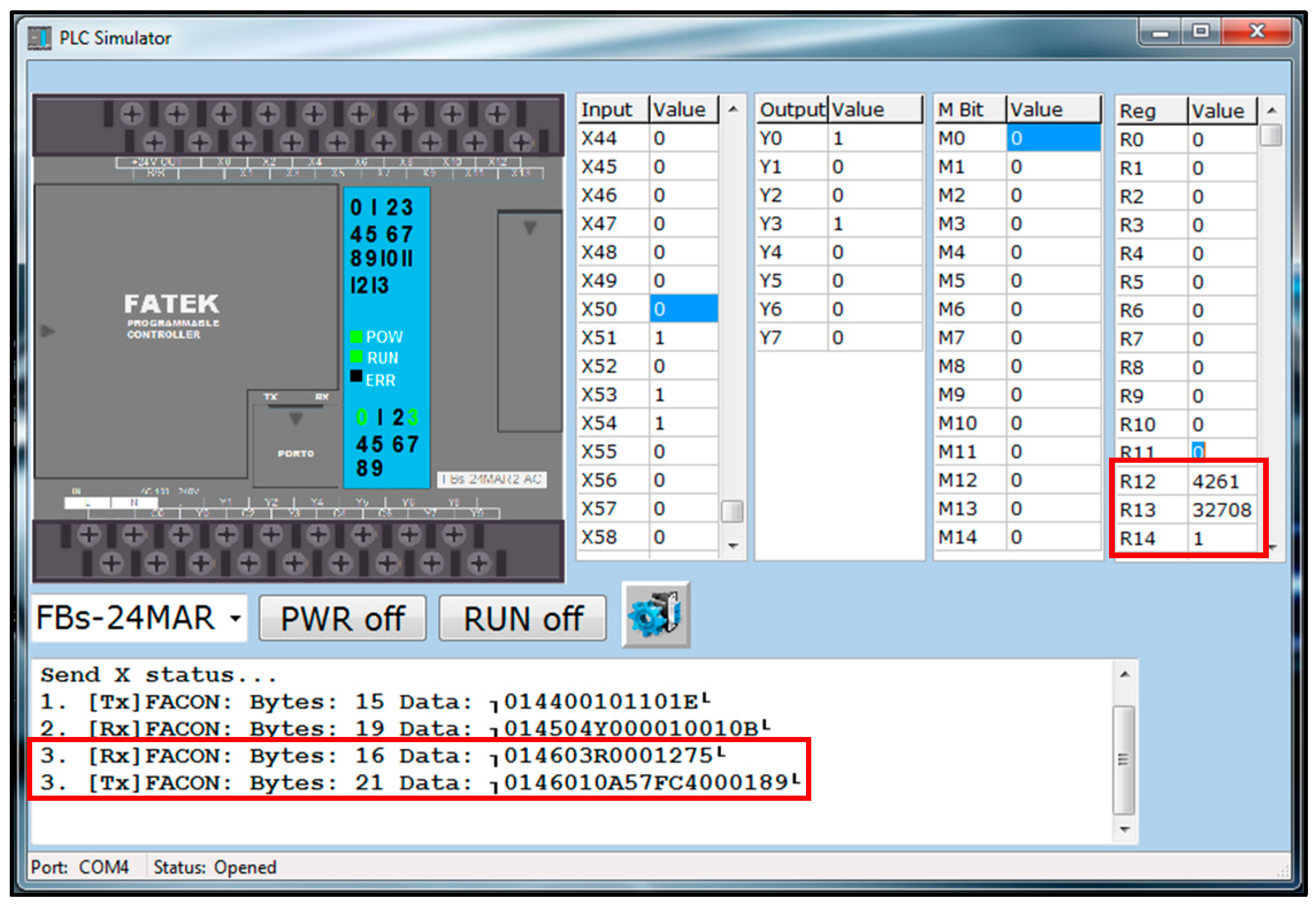
Reading register-type resources—0x46: Read multiple consecutive registers. In this test, a message is sent with data for reading register values R12–R14, a total of three registers, using a template message [
10] shown in
Figure 14—command 0x46.
Figure 15 and
Figure 16 show the screens with the settings of the two programs and the messages that are transmitted between them.
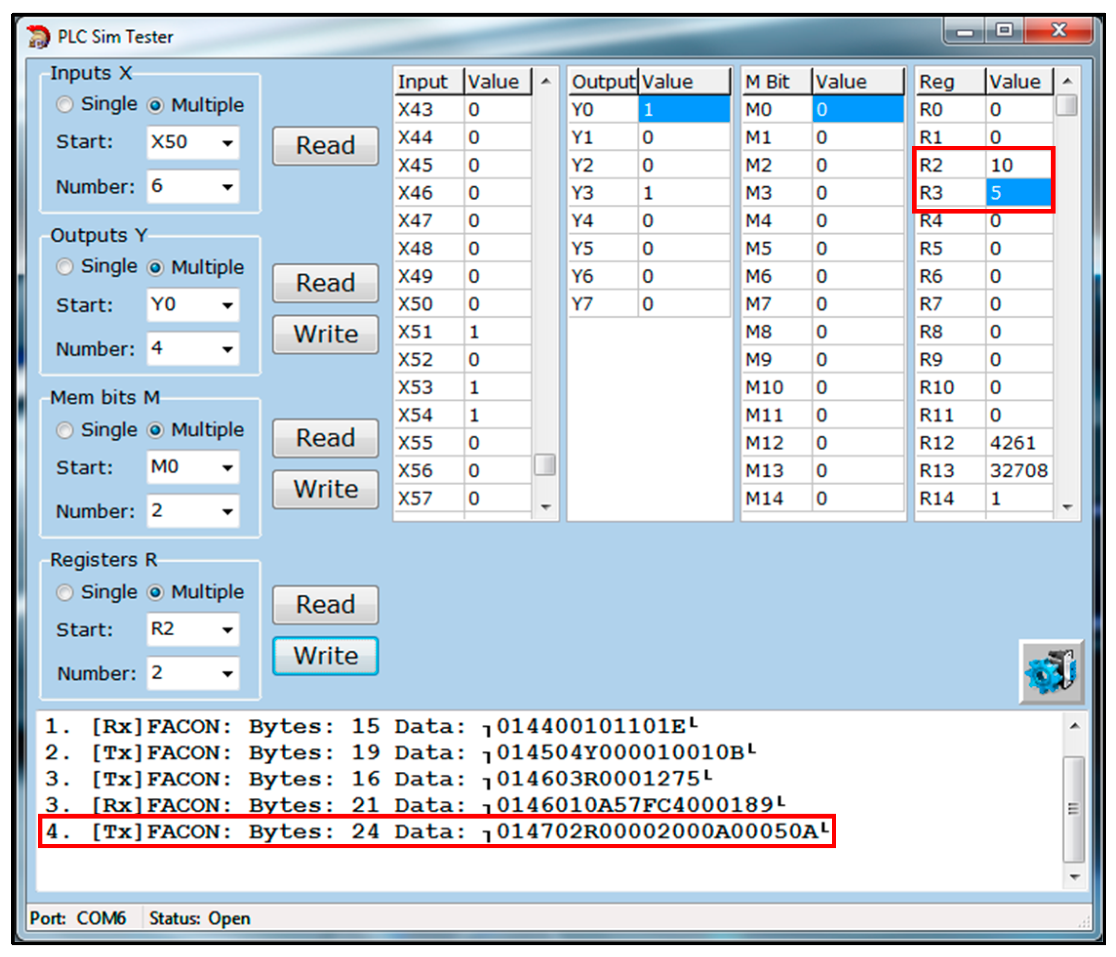
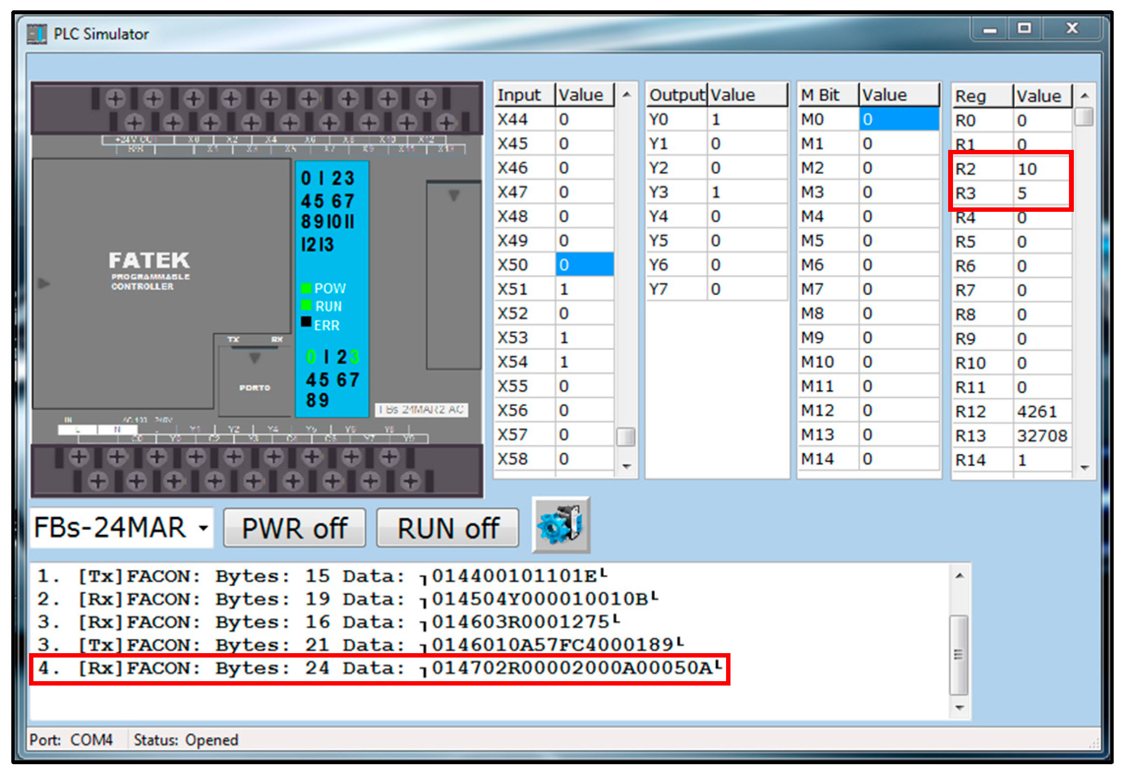
Writing register-type resource—0x47: Write multiple consecutive registers. This test was conducted with the execution of a message that is not a part of the template messages in order to show the correct operability of both programs. The documentation presents a message [
10] for writing data to a WY-type register. For the experiment, writing to R-type registers was chosen—in R2 and R3 the data 0x000A and 0x0005 were written, and the correct CRC was calculated in advance. The figure shows the structured command, as presented in the protocol documentation. (
Figure 17).
Figure 18 and
Figure 19 show the screens with the settings of the two programs and the messages that are transmitted between them.
Results of the experiments:
At the communication level, correctly formed messages are sent and received according to the protocol’s requirements. The messages shown in the experimental part completely match the template messages provided in the official documentation of the FACON [
10] protocol. This guarantees that all types of messages will be correct.
At the application level, the received data are processed correctly, which is confirmed by the visualization of the data in the corresponding tables. This guarantees that during subsequent processing for specific calculations, the data will be correct both in the simulator (controller) and in the processing program installed on the computer.
When developing the necessary SCADA and HMI programs, they will correctly process messages from a real controller. This will save time for tests of sending/receiving messages from a real controller or from the developed simulator if necessary.
6. Conclusions
The presented experiment and results (several of which are presented in this paper) show the correct receiving and sending of messages at the channel level and the correct processing at the application level. The correct work is confirmed by template messages from FACON documentation and user-constructed test messages. The correct application-level preprocessing of messages is confirmed via tables with memory data (inputs/outputs/memory bits and registers). The simulator thus developed can be used in a real environment when developing SCADA and HMI-type software.
In subsequent development, the platform may be enhanced with the implementation of program-based logic for controlling technological processes for the purpose of full simulation of the controllers.
Author Contributions
Conceptualization, I.B. and G.S.; methodology, I.B.; software, I.B.; validation, I.B. and G.S.; formal analysis, I.B.; investigation, I.B. and G.S.; resources, I.B. and G.S.; data curation, I.B.; writing—original draft preparation, I.B.; writing—review and editing, I.B. and G.S.; visualization, I.B.; supervision, I.B. and G.S.; project administration, I.B. and G.S.; funding acquisition, G.S. All authors have read and agreed to the published version of the manuscript.
Funding
The scientific research, the results of which are presented in this paper, was carried out under project NP3 within the framework of the scientific research activity inherent to TU-Varna, funded by the state budget.
Institutional Review Board Statement
Not applicable.
Informed Consent Statement
Informed consent was obtained from all subjects involved in the study.
Data Availability Statement
The original contributions presented in this study are included in the article. Further inquiries can be directed to the corresponding author(s).
Conflicts of Interest
The authors declare no conflicts of interest.
References
- Pruna, E.; Bayas, F.; Cocha, H.; Escobar, I.; Gordon, A.; Constante, P. Implementation of a simulator of industrial processes. In Proceedings of the 2016 IEEE International Conference on Automatica (ICA-ACCA), Curico, Chile, 19–21 October 2016; pp. 1–6. [Google Scholar] [CrossRef]
- Pinto, V.; Rafael, S.; Martins, J.F. PLC controlled industrial processes on-line simulator. In Proceedings of the 2007 IEEE International Symposium on Industrial Electronics, Vigo, Spain, 4–7 June 2007; pp. 2954–2957. [Google Scholar] [CrossRef]
- Palma, L.B.; Rosas, J.A.; Pecorelli, J.; Gil, P.S. Structured Text simulator for PLC in learning environment. In Proceedings of the 2015 International Conference on Information Technology Based Higher Education and Training (ITHET), Lisbon, Portugal, 11–13 June 2015; pp. 1–7. [Google Scholar] [CrossRef]
- Changsakol, P.; Chotikakamthorn, N.; Wongwirat, O. A Joint Controller-Simulator Programming by Demonstration Method for PLC Devices. In Proceedings of the 2006 IEEE Conference on Cybernetics and Intelligent Systems, Bangkok, Thailand, 7–9 June 2006; pp. 1–6. [Google Scholar] [CrossRef]
- Yakimov, P.; Iovev, A.; Tuliev, N.; Balkanska, E. Development of Hardware and Software Methods and Tools for a Successful PLC Training. In Proceedings of the 2019 X National Conference with International Participation (ELECTRONICA), Sofia, Bulgaria, 16–17 May 2019; pp. 1–4. [Google Scholar] [CrossRef]
- Cerezo, J.M.; León, S.; Vega, E.; Vega, A. CQMIH PLC simulator host-link communications protocol experience. In Proceedings of the 2016 Technologies Applied to Electronics Teaching (TAEE), Seville, Spain, 22–24 June 2016; pp. 1–6. [Google Scholar] [CrossRef]
- Park, C.M.; Bajimaya, S.M.; Park, S.C.; Wang, G.N.; Kwak, J.G.; Han, K.H.; Chang, M. Development of Virtual Simulator for Visual Validation of PLC Program. In Proceedings of the 2006 International Conference on Computational Inteligence for Modelling Control and Automation and International Conference on Intelligent Agents Web Technologies and International Commerce (CIMCA’06), Sydney, NSW, Australia, 28 November–1 December 2006; p. 32. [Google Scholar] [CrossRef]
- Aouichak, I.; Kergosien, Y.; Elfeki, I.; Le Bunetel, J.-C.; Raingeaud, Y.; Billaut, J.-C. Multipath model simulator for PLC home networks. In Proceedings of the 2017 International Symposium on Electromagnetic Compatibility—EMC EUROPE, Angers, France, 4–7 September 2017; pp. 1–5. [Google Scholar] [CrossRef]
- Chattal, M.; Bhan, V.; Madiha, H.; Shaikh, S.A. Industrial automation & control trough PLC and Labview. In Proceedings of the 2019 2nd International Conference on Computing, Mathematics and Engineering Technologies (iCoMET), Sukkur, Pakistan, 30–31 January 2019; pp. 1–5. [Google Scholar] [CrossRef]
- Main Unit Manual—Advanced Application (Manual_2_All_en.zip (Appendix 1.pdf—Appendix 1 FATEK Communication Protocol)). Available online: https://www.fatek.com/en/download.php?act=list&cid=150 (accessed on 24 April 2025).
| Disclaimer/Publisher’s Note: The statements, opinions and data contained in all publications are solely those of the individual author(s) and contributor(s) and not of MDPI and/or the editor(s). MDPI and/or the editor(s) disclaim responsibility for any injury to people or property resulting from any ideas, methods, instructions or products referred to in the content. |
© 2025 by the authors. Licensee MDPI, Basel, Switzerland. This article is an open access article distributed under the terms and conditions of the Creative Commons Attribution (CC BY) license (https://creativecommons.org/licenses/by/4.0/).


