1. Introduction
Profile shift coefficients have been widely used to adjust the operating characteristics of the gears in mesh. An involute profile allows such modifications to be performed easily and inexpensively by adjusting the distance of the forming tool geometry with regard to the pitch circle of the gear. Thus, a different portion of the involute curve formed by the base circle of the gear can be used. This modification may have several benefits, like avoiding the undercut or pointing of the tooth, especially when gears with a small number of teeth are use; improving certain parameters like the root and contact strength, transverse contact ratio, sliding velocities; and tailoring the dimensions and center distances of the gears in mesh. The last is of great importance for achieving assembly and coaxiality conditions in planetary gear trains. In some cases, with a careful consideration and selection of profile shift coefficients, certain arrangements can be designed that offer several advantages. Below, applications in some planetary gear trains are reviewed.
1.1. [AAI] Gear Train
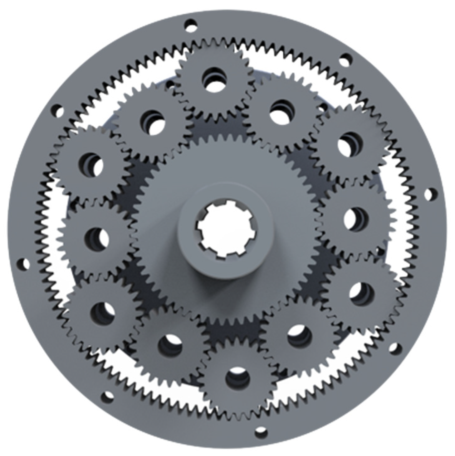
The gear train is also known as the full planet or full pinion engagement planetary gear train—FPE [
1]. In this type of gear train, all the planets are meshed with the adjacent planets, forming a closed loop, with the inner row meshing with the sun gear and the external row meshing with the ring gear—
Figure 1.
Achieving this is only possible with the careful consideration of the number of teeth in the mesh and then applying the necessary profile shift coefficients so that the necessary center distances are achieved. The difficulty lies in that this is a constrained system, and altering the dimension and center distances of each gear directly affects the dimensions and relations of adjacent gears as well, as represented as green lines in
Figure 2.
Thus, great care should be taken so that both the number of teeth and profile shifts are within practically possible ranges and acceptable working parameters for all the gears in the system. In [
1] this gear train is examined, and guidelines for choosing the number of teeth in each gear and finding the necessary center distances are provided.
1.2. The Schaeffler Lightweight Differential
An interesting approach for creating compact designs using profile shifts is the Schaeffler differential presented in [
2]. The proposed configuration is a spur gear system rather than the typical bevel gear used in most differentials. This is not a new concept, with the first patent for a spur gear differential by A. Brown dating back to 1902 [
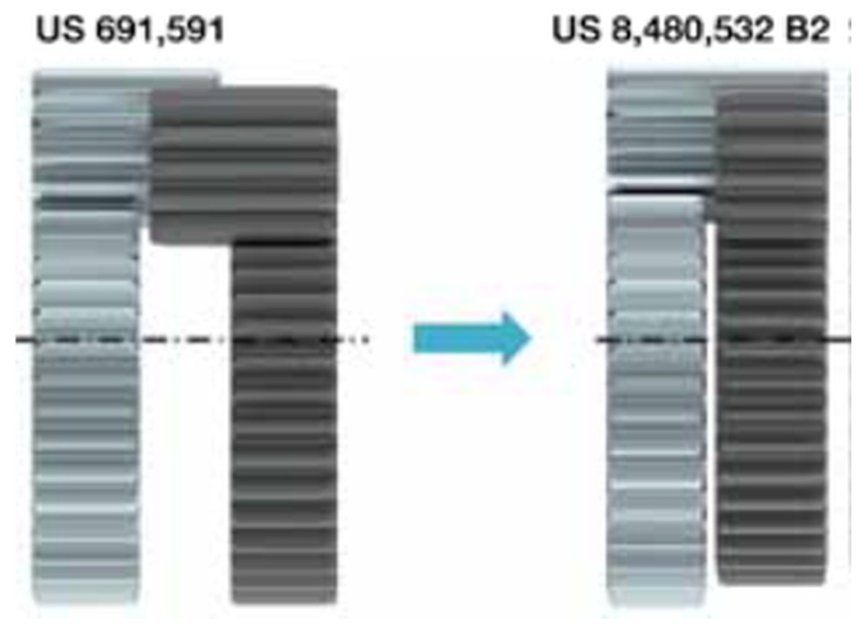
3]. The company manages to improve on the existing designs by adjusting the size and center distances of the gears in mesh using a profile shift, thus enabling smaller packaging by eliminating the axial gap between the two sun gears—
Figure 3.
This is achieved by applying a rather extreme positive profile shift to one of the sun gears and a negative one to the other—
Figure 4. However, the module and number of teeth on both gears remain unchanged, so the ratio of the transmission is unaffected as well, despite the difference in size. By applying this technique, the company claims to improve the parameters of the differential, resulting in a lower weight and size and reduced fuel consumption and emissions [
2].
2. AA Gear Train
2.1. Operational Characteristics
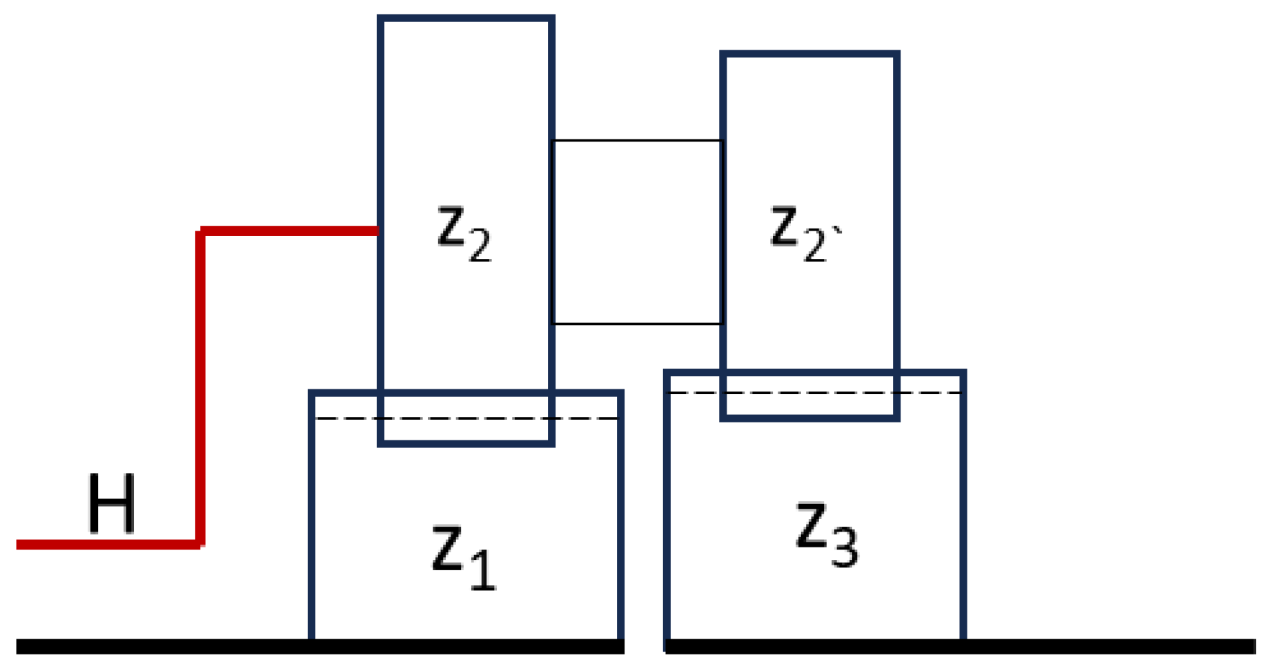
This article aims to propose and examine a similar approach for a type of planetary gear train that consists of two central external gears, z1 and z3, and a stepped planet mounted on one carrier—H. It can be referred to as a type of 2K-H gear train, but a more specific designation is given by K. Aranudov in [
4], where it is denoted as an AA gear train, meaning that there are two external gears, one carrier, and no internal gear-
Figure 5.
The design enables a significant reduction or increase in the speed within a single stage and compact dimensions. More on its characteristics can be found in [
4,
5]. The internal gear ratio
i0 is defined by
The usual mode of operation is as a reducer gear train with one of the central gears fixed, input through the carrier and output through the other central gear. In this case, the ratio of this mechanism is defined by the following equation:
It is apparent that the ratio depends on the difference in the teeth of the two central gears. Given that all the gears in mesh are the same module, their pitch diameter is d = m.z. This means that with different numbers of teeth, the diameters of both central gears are different. Therefore, a stepped planet consisting of larger and smaller gears fixed together is needed to compensate for the size difference. The approach presented in this article uses a profile shift to adjust the dimensions of the two central gears so that the diameters of both are close to equal. This negates the need of a stepped planet, and a simple spur gear with a fixed number of teeth can be used on both—
Figure 6.
This design has several advantages. The main one being that it is much simpler and cheaper to manufacture. Stepped planets are difficult to fabricate, especially when the angular position of the teeth on the smaller and larger gear must be aligned. This brings us to the other advantage. Because of this alignment, in practice the mesh load factor, kγ, of stepped planets is worse than that of conventional spur gears with no steps because they are more prone to manufacturing errors. However, this assumption must be empirically confirmed with a special test rig and test gear trains, which is the subject of another research project. Generally, the value of kγ for AA gear trains is difficult to calculate, depending largely on the manufacturing accuracy.
2.2. Profile Shift Range
However, the conditions in which the design can be achieved without stepped planets are practically limited. The main limitation is the range of the profile shift which can be applied to the gears without it resulting in excessive pointing or undercuts, as well as other working parameters like the contact ratio, considerable tooth weakening, a short involute, or possible interferences. The usual maximum recommended values are a positive profile shift of x = +1.5 and a negative profile shift of x = −1. However, this differs depending on the number of teeth used in each of the central gears. Gears with a larger number of teeth can tolerate a greater profile shift, while gears with a small number of teeth suffer from both a small applicable range of profile shifts and the hazard of the transverse contact ratio falling below recommended values. In
Figure 7, the difference between two gears with module 1 and a positive profile shift of x = +1 and 20 and 80 teeth is presented.
It is apparent that for the same profile shift value, the teeth of the smaller gear are pointed beyond the recommended values for the minimum addendum tooth thickness of 0.2 of the module. Other parameters, like the transverse contact ratio, are also increased with a small number of teeth.
This highlights one of the disadvantages of this design—profile shifts are selected depending on the diameter compensation requirements rather than working parameters, like balanced specific sliding and improving the root and contact strength of gears, etc. More information on profile shifts in gears and how they affect the performance of the gear train can be found in [
4,
6,
7].
2.3. Assembly Conditions
The other factor of importance when choosing the profile shift is the number of planets, p, used in the transmission. To satisfy the assembly condition of this design, the following requirement must be met:
It is apparent that the smallest tooth number difference between the two central gears must be at least equal to the number of planetary gears. This means that it is rather easy to achieve compensated gears when the number of planets is small. For instance, if only one planet is used, p = 1, then only a single tooth difference is needed, and the profile shift adjustments of each central gear are within a smaller range The profile shifts must be selected so that the center distances,
aw, between the two central gears and the planet gear are equal:
To satisfy this condition the following must be observed:
Each working pressure angle α
w can be found with the following formula:
In
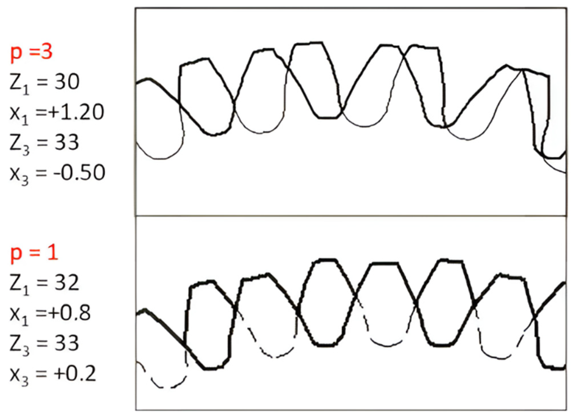
Figure 8, a comparison between two compensated gear trains is presented. When three planets, p = 3, are used, the difference in the tooth count is also three; this means that the profile shift compensation should be large enough to bring the diameters of the two central gears to near equal dimensions. A much smaller profile shift compensation is needed with only one tooth difference.
As noted previously, a very large value for both the positive and especially negative profile shift may not be practically possible, or it may be detrimental to the performance of the gear train. With p = 3 the required profile shift for the z
3 gear is x = −0.5, which makes it significantly weaker when bending than z
1, as the tooth is much thinner. With p = 1 the required difference in the profile shift between the two central gears is much lower, providing a larger range of selection for profile shifts and a more balanced performance of gears in mesh. In contrast, using less planets decreases power branching capabilities, thus increasing the volume and weight of the gear train. In
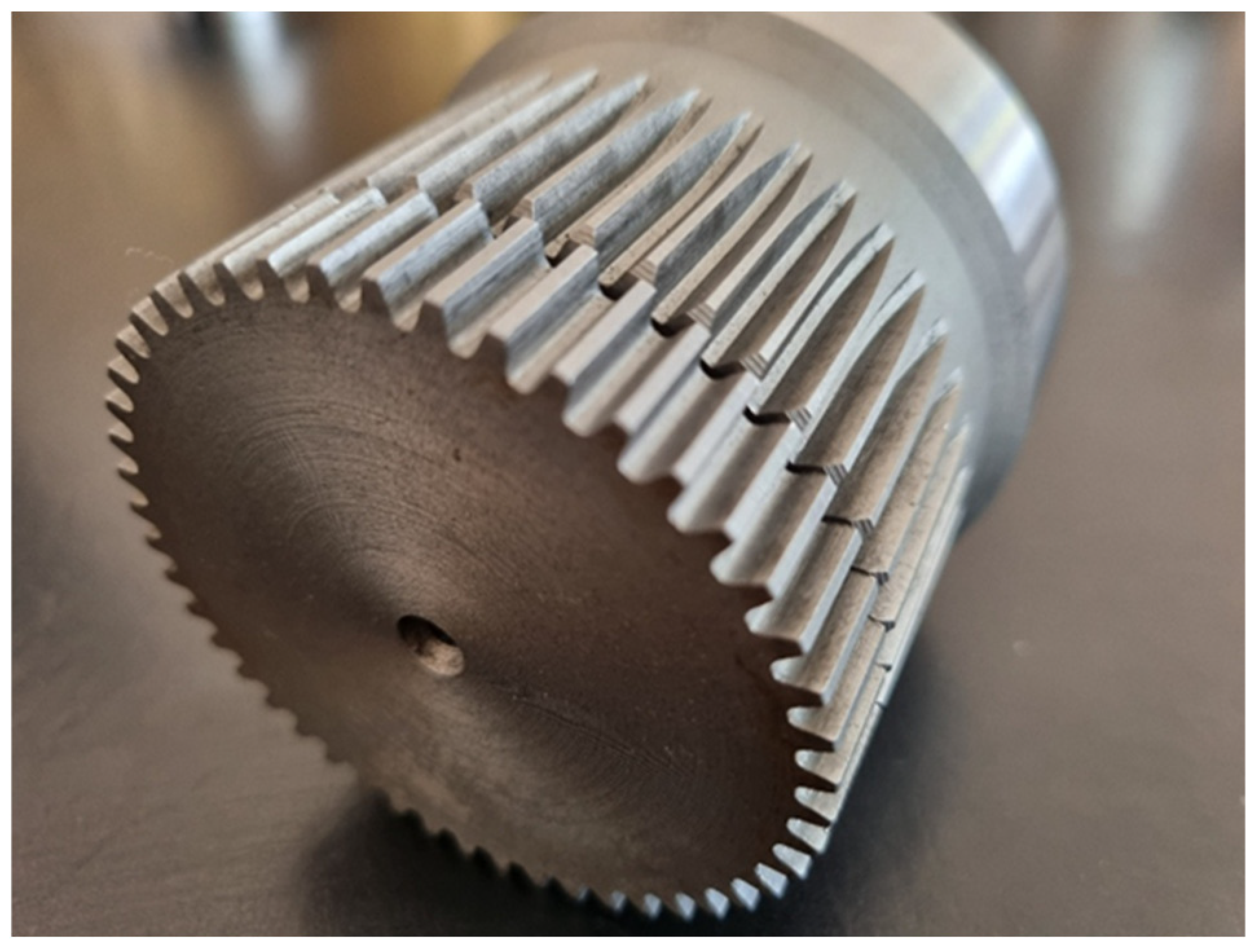
Figure 9 an actual AA gear train with compensated central gears and a ratio of 16:1 is shown. In has 45 teeth on z
1, 48 teeth on z
3, and three equally spaced planets.
2.4. Other Considerations
The AA type of gear train, while providing high ratio possibilities at a single stage and a low volume, suffers from a decreasing efficiency with the increase in the gear ratio. It can be approximately calculated by the following formulas [
4]:
A graphical representation of the efficiency is shown in
Figure 10 [
8]. The AA gear train in article [
8] is represented as concept C.
As the efficiency decreases, the self-locking of the gear train occurs. Also, the efficiency differs depending on whether the gear train works as a reducer or multiplicator, indicating that the drive may not be reversible. This is not always a desired effect. More information on the self-locking condition can be found in [
9]. As stated previously, the higher the number of the teeth of the central gears, the higher the possibilities of the profile shift adjustment and planet gears in mesh, but according to Formulas (1) and (2), this leads to a higher gear ratio and thus lower efficiency and possible self-locking. On the other hand, the lower number of the teeth of the central gears leads to higher efficiency and less volume, but the speed ratio and power branching capabilities are very limited. Also, it is worth noting that inadequate choice of profile shifts may result in the reduced performance of the gear train and accelerated wear, despite complying with the assembly conditions of the gear train. Good information on the wear of gears depending on the profile shift coefficient is presented in [
10]. The designer of the gear train must work within tight parameters to achieve the desired result.
3. Conclusions
The presented approach for designing AA gear trains without stepped planets offers some opportunities, which provide certain advantages mainly in terms of manufacturing, cost, and volume. As discussed in this article, the possibilities are limited, largely depending on the practically applicable profile shift. Despite these limitations, this design may be feasible when speed ratios between 10 and 25 are desired. Compared to other planetary gear mechanisms, this is achievable within a single stage and with a small volume. Also, in this range of speed reduction, the efficiency is still acceptable. The absence of an internal gear reduces the radial dimensions and cost, since large internal gears are one of the most expensive parts in a planetary gear train. When a lower efficiency is acceptable, large gear reductions and increased power branching by means of more planet gears are achievable. However, the capabilities remain limited compared to gear trains incorporating stepped planet gears. By avoiding stepped planet gears, the load sharing factor should theoretically be better, but still an empirical study must be conducted to verify results.
Funding
This research received no external funding.
Institutional Review Board Statement
Not applicable.
Informed Consent Statement
Not applicable.
Data Availability Statement
Data are available upon reasonable request to the corresponding author.
Acknowledgments
This research is supported by the Bulgarian Ministry of Education and Science under the second stage of the National Program “Young Scientists and Postdoctoral Students–2”.
Conflicts of Interest
The author declares no conflicts of interest.
References
- Alexandrov, A. Synthesis of Full Planet Engagement Planetary Gear Train. Ph.D. Thesis, Technical University of Sofia, Sofia, Bulgaria, 2023. [Google Scholar]
- Blermann, T.L. Compact and Efficient, Schaeffler Differential Systems Set the Pace; Schaeffler Technologies AG &, Co. KG: Herzogenaurach, Germany, 2010. [Google Scholar]
- Brown, A.T. Gearing. U.S. Patent US691591A, 21 January 1902. [Google Scholar]
- Arnaudov, K.; Karaivanov, D. Planetary Gear Trains; Publishing House of BAS “Prof. Marin Drinov”: Sofia, Bulgaria, 2017. (In Bulgarian) [Google Scholar]
- Looman, J. Zahnradgetriebe–Grundlagen, Konstruktion, Andwendung in Fahrzeugen; Springer: Berlin/Heidelberg, Germany, 1996. [Google Scholar]
- Tomori, Z. An Optimal Choice of Profile Shift Coefficients for Spur Gears. Machines 2021, 9, 106. [Google Scholar] [CrossRef]
- Belarhzal, S.; Daoudi, K.; Boudi, E.M.; Bachir, A.; Elmoumen, S. A Multiobjective Optimization Analysis of Spur Gear Pair: The Profile Shift Factor Effect on Structure Design and Efficiency. Math. Probl. Eng. 2021, 10, 8873769. [Google Scholar] [CrossRef]
- Hoehn, B.; Stahl, K.; Gwinner, P. Lightweight Design for Planetary Gear Transmissions. Gear Technol. 2013, 30, 96–103. [Google Scholar] [CrossRef]
- Salgado, D.; Castillo, J.M. Conditions for Self-Locking in Planetary Gear Trains. J. Mech. Des. Trans. ASME 2007, 129, 960–968. [Google Scholar] [CrossRef]
- Liu, W.; Zhu, R.; Zhou, W. Calculation and Analysis of TVMS Considering Profile Shifts and Surface Wear Evolution Process of Spur Gear. Chin. J. Mech. Eng. 2024, 37, 73. [Google Scholar] [CrossRef]
| Disclaimer/Publisher’s Note: The statements, opinions and data contained in all publications are solely those of the individual author(s) and contributor(s) and not of MDPI and/or the editor(s). MDPI and/or the editor(s) disclaim responsibility for any injury to people or property resulting from any ideas, methods, instructions or products referred to in the content. |
© 2025 by the author. Licensee MDPI, Basel, Switzerland. This article is an open access article distributed under the terms and conditions of the Creative Commons Attribution (CC BY) license (https://creativecommons.org/licenses/by/4.0/).
