Proceeding Paper

Electromagnetic Compatibility Analysis in the Design of Reliable Energy Systems of a Telecommunication Equipment †

1
CETIN Bulgaria Ltd., 1000 Sofia, Bulgaria
2
Department of Telecommunications, University of Telecommunications and Post, 1700 Sofia, Bulgaria
3
Department of Electricity and Automation, University of Mining and Geology “St. Ivan Rilski”, 1700 Sofia, Bulgaria
4
Department of Computer Science, University of Ruse “Angel Kanchev”, 7017 Ruse, Bulgaria
5
Department of Software Engineering, Cisco Systems Bulgaria, 1700 Sofia, Bulgaria
*
Author to whom correspondence should be addressed.
Presented at the International Conference on Electronics, Engineering Physics and Earth Science (EEPES 2025), Alexandroupolis, Greece, 18–20 June 2025.
Eng. Proc. 2025, 104(1), 29; https://doi.org/10.3390/engproc2025104029
Published: 25 August 2025

Abstract

The reliability of power supply systems is of utmost importance for telecommunications. In our daily lives, we are used to having constant access to the power grid with negligible risks. Standards and practices established over the years guarantee minimal problems for the household consumer and accidents in their electrical appliances. Often, the biggest inconvenience of a power failure for the average person is having to set the clock on the stove or use the flashlight on their phone. However, we rarely realize how fragile the balance on which all this is based is, but telecom companies are fully aware of this fact. Regardless of whether the problem comes from natural phenomena, accidental or intentional damage, or defects in the equipment, the equipment used in telecommunications technologies is extremely sensitive, and it is necessary to take protective measures.

1. Electromagnetic Compatibility (EMC)

The concept of “electromagnetic compatibility” (EMC) in the field of communications has two aspects:
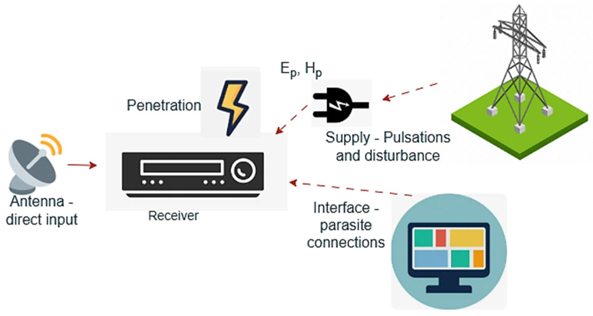
On the one hand, this is electromagnetic interference (EMI). The concept includes the potential danger of mutual parasitic influence between communication devices and communication channels during their operation. A similar danger exists in all modern wireless and wired systems and for all devices in them [1,2]. Any device with a certain function from a given system can have an unacceptable effect on another device from the same system or from another system, and vice versa. Therefore, each device and system must be designed so that this parasitic EMI influence in both directions is minimal. The most common situation of electromagnetic interference in communications is the following: a given “EMI source” causes parasitic effects in a given “victim device” (disturbed device) [2,3]. This can happen either via a “wired” connection, or via a purely electromagnetic (wireless) connection, or both. An example is shown in Figure 1.
In a “wired connection”, parasitic currents Ip flow through the connecting wires and parasitic voltages Vp appear, which disrupt the main operation of the victim device. In a “wireless connection”, secondary electric and magnetic high-frequency fields Ep and Hp are excited in the disturbed device, which ultimately excite parasitic currents and voltage in the conductor lines in it.
The most common sources of EMI in communications are oscillators and synthesizers, controlled switches, fast digital switches, fiber-optic emitters, etc. (of course, and parasitic signals in and out of the band of a given device). The most common victim devices are various receiving or “non-receiving” devices and systems—computer systems, telephones, security systems, digital processors, and many others. The most common elements through which interference appears are lines on the boards, inductive and capacitive elements, holes in the housings, defective or missing grounding, etc. An example is shown in Figure 2.
Unwanted EM emissions from EMI sources can be transmitted to other devices in two main ways:
  • Through direct galvanic connection with wires;
  • By irradiation with an electromagnetic (EM) field (including EM induction).
A business model for EMC management is needed, but this can only happen after clear actions have been taken. This includes addressing the issue and implementing various technical means to reduce EMC [4]. Most often, the effect of EMI interference is associated with the excitation of parasitic currents and voltages in the transmission lines in a given device. This can happen in several ways [5]:
  • Through concentrated parasitic currents (parallel to the main) and voltages (sequential) at any location in the line, e.g., in the feeder lines from the input antenna, when powering the active elements, in the control switches, etc.;
  • By distributed irradiating EM fields, exciting parasitic currents and voltages in the line; if the sources of the fields are far away, this is plane wave irradiation; if the sources are close, the excitation has a spatial distribution and is accounted for in a complex manner;
  • Through capacitive and inductive interaction between adjacent lines (cross coupling, crosstalk, sometimes motors) [6]. This is a common problem within complex devices with a high level of integration (VLSI); to account for it, mutual capacitances and inductances must be known; reliable estimates are made with EM simulations;
  • Through common resistances between the lines (resistance coupling); most often, the mechanism manifests itself in non-ideal screens and non-ideal grounding surfaces; parasitic currents and voltages are excited in them, which pass through the common resistance into the disturbed line, which should be protected. For these reasons, shielding and grounding are very important in devices and systems.

2. EMI Protection Methods

2.1. Grounding and Bonding

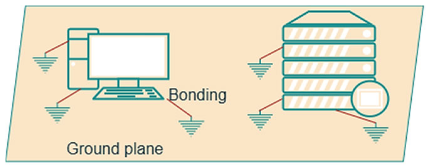
One of the most important methods of EMI protection is “grounding” [7]. This is the provision of an equipotential surface with a stable “zero” potential. By bonding zero-resistance conductors to it, certain parts of the device are “grounded”. An example is shown in Figure 3.
In general, grounding at more than one point is not equipotential. To equalize the zero potential, additional bonding, common ground plates, or networks are used, in which the distance between the metal bars depends on the frequency at which the grounding will be carried out (more densely at higher frequencies). An example is shown in Figure 4.

2.2. Shielding

Shielding is the main tool for solving EMC problems. It protects devices from unwanted signals and greatly limits EMI sources. In many cases, a solid metal box without holes and gaps is the best shield for electronic devices. Designing shields is a complex task, and today, software simulators are used for this purpose. In simple cases, the following formula for shielding losses S, dB is applicable:
S = A + R   ± B ,   d B
where A is absorption losses in the screen, R is reflection losses, and B is the correction factor due to multiple reflections.
The effectiveness of shielding depends on the type of shielded fields, the properties of the materials used for shielding, the geometry of the structure, the depth of field penetration, etc. 50-ohm coaxial cables are the most versatile. They consist of an inner core and an outer grounded braid. The signal is well shielded from external fields. Cheaper solutions at lower frequencies (e.g., ADSL) are twisted pairs with unbalanced or balanced power supply. Twisting is used to suppress the differential mode field, but the effect decreases with increasing frequency. Ferrite suppressors are used to reduce high-frequency interference, which do not require grounding. An example is shown in Figure 5.

2.3. Interference Protection Elements

To adequately protect sensitive electrical systems, thereby ensuring reliable operation, transient suppression measures should be part of the initial design process, not simply included as an afterthought. To effectively suppress transients, the selected protective device must be able to dissipate the transient pulse energy at a sufficiently low voltage so that the operation of the protected circuit is maintained [8]. This is achieved through the use of various voltage limiting elements, current sinking elements, circuits, and filters [9,10]. An example is shown in Figure 6.
Managing electromagnetic compatibility would lead to reduced network losses and increased revenues [3,11].

3. An Example of a Reliable Power System in Telecommunications

A reliable power system should be designed to meet all of the factors mentioned so far. It is also desirable that as many of the elements in it as possible are additionally secured, giving time to react in the event of a failure of any of them [12,13,14].
An example of a reliable energy system is shown in Figure 7. We will consider the implementation of a facility owned by one of the telecom companies in Bulgaria. The newly proposed system has already been installed and works flawlessly.
Specifically, we consider an object that is a transmission point, and as mentioned, they are treated as consumers of the highest priority. This requires that the object is powered by three independent sources and that there are no interruptions during the switching from one to the other.
The three independent power sources are as follows:
  • Diesel Generator—The generator system consists of a diesel generator (Model TJ8PE-1; manufacturer TEKSAN, Istanbul, Turkey) and an intermediate power panel containing an Automatic Voltage Regulator (AVR). An example is shown in Figure 8. To control the parameters in the network, digital control of the diesel generator is offered and shown in Figure 9.
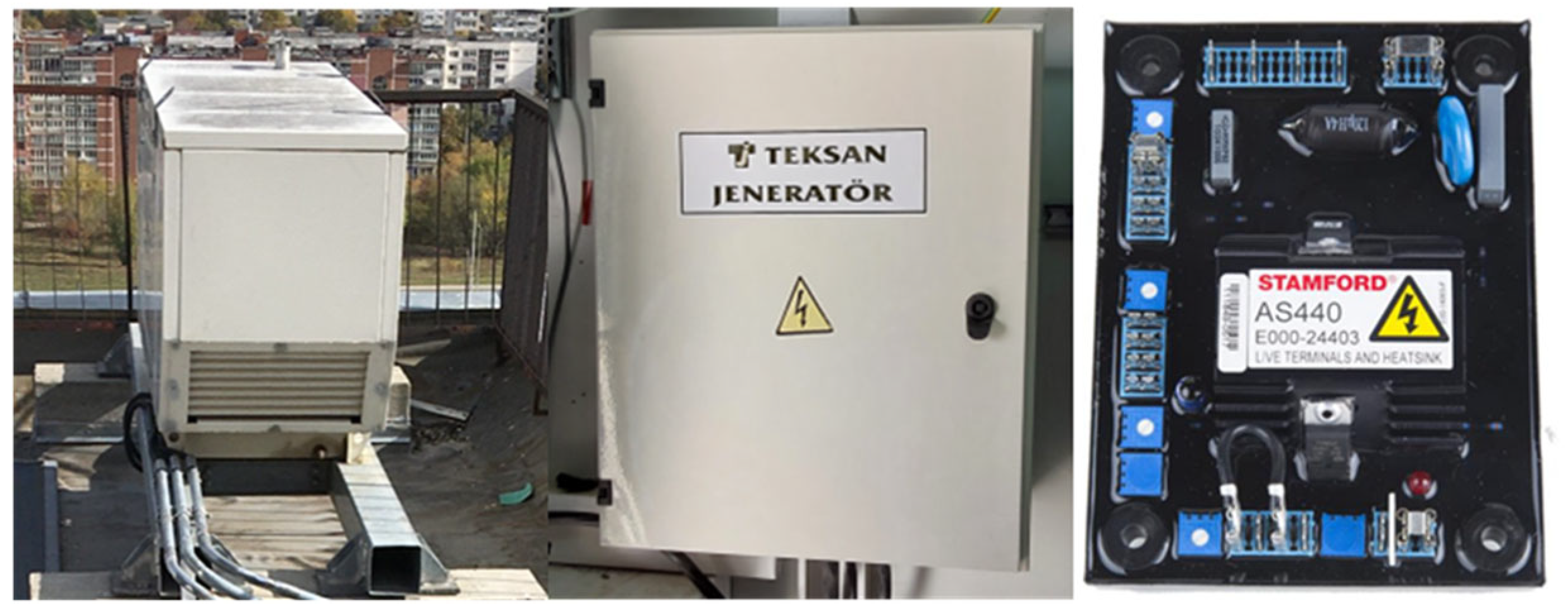
Figure 8. View of an emergency power generator system.
Engproc 104 00029 g008
Figure 9. View of DSE 7420 MKII control unit: (a) front view; (b) connection.
Engproc 104 00029 g009
2.
Uninterruptible power supply—The power supply devices (Model TESS 400E; manufacturer TEKSAN, Istanbul, Turkey) serving the equipment of the site are provided with several strings (threads) of rechargeable batteries that maintain the power supply of the site until the power is switched to the generator in case of an emergency. The charge in the battery strings is sufficient to provide power to all equipment for about 4 h, and in critical situations, when powering only the most important equipment for 10–16 h. Usually, there is an artificial delay in starting the generator until the batteries reach a certain voltage drop threshold; thus, during shorter power outages, less fuel is consumed, and environmental pollution is reduced. The batteries are charged by solar panels, and there is a system for monitoring their charge and discharge. An example is shown in Figure 10.
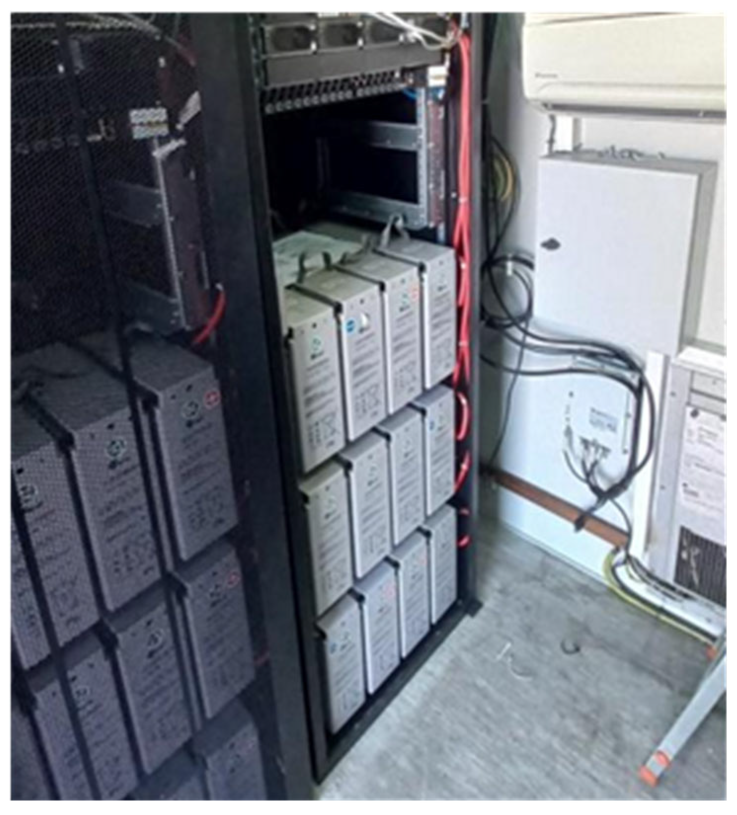
Figure 10. UPS of the base station.
Engproc 104 00029 g010
3.
Three-phase power supply from the public electricity grid—The national electricity grid is used for the main power supply in normal operation. The control panel connecting the site to the “external” power supply is additionally equipped with a connection socket and a manual switch for adding a backup portable generator to the system in case of a failure in the main one. You can see an example in Figure 11.
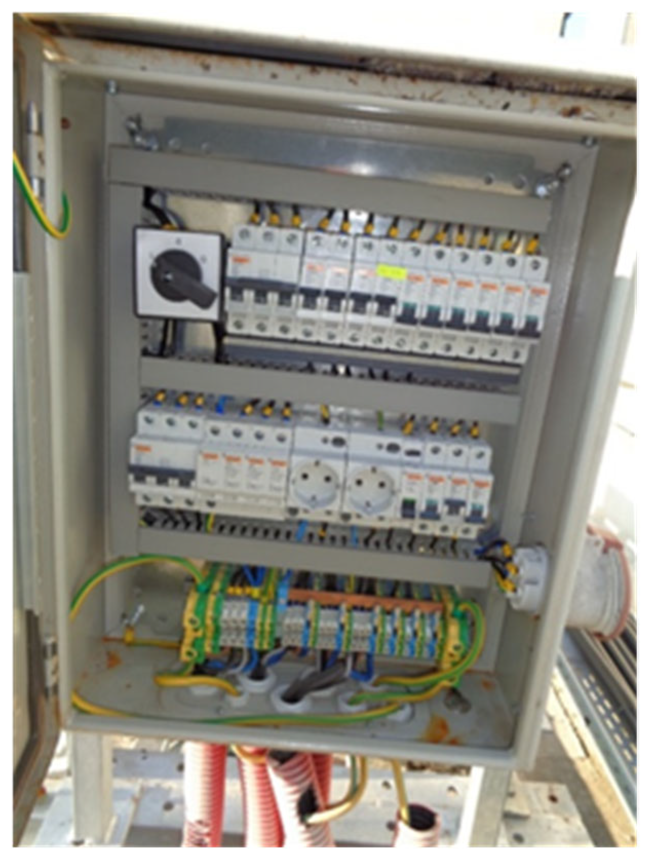
Figure 11. View of an external power supply control panel of the base station.
Engproc 104 00029 g011
In addition, it is good practice to maintain a backup of power supplies:
  • Two independent power sources—This approach uses two separate power supply units connected to the main panel. One unit is used exclusively for high-priority equipment, while the other powers everything. Active equipment is designed with the ability to receive power from two parallel sources. This ensures that, in the event of a power supply unit, wiring line, or consumer failure, the equipment will continue to operate. Additionally, it can be noted that power supply units are modular systems that allow “hot swap” (change under voltage) of some of the elements on them. Such elements are, for example, batteries and rectifier modules. An example is shown in Figure 12;
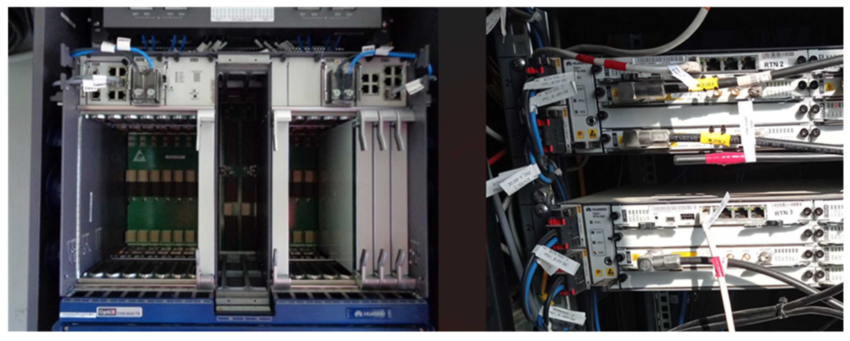
Figure 12. Parallel power supply of the equipment of a base station.
Engproc 104 00029 g012
  • Active control of consumers—The power supply units have two power buses (Manufacturer TEKSAN, Istanbul, Turkey) (high priority and low priority); when powered by batteries, the power supply unit controller monitors their voltage. After a preset voltage drop threshold, the controller turns off the power supply to the low-priority bus in order to reduce consumption.
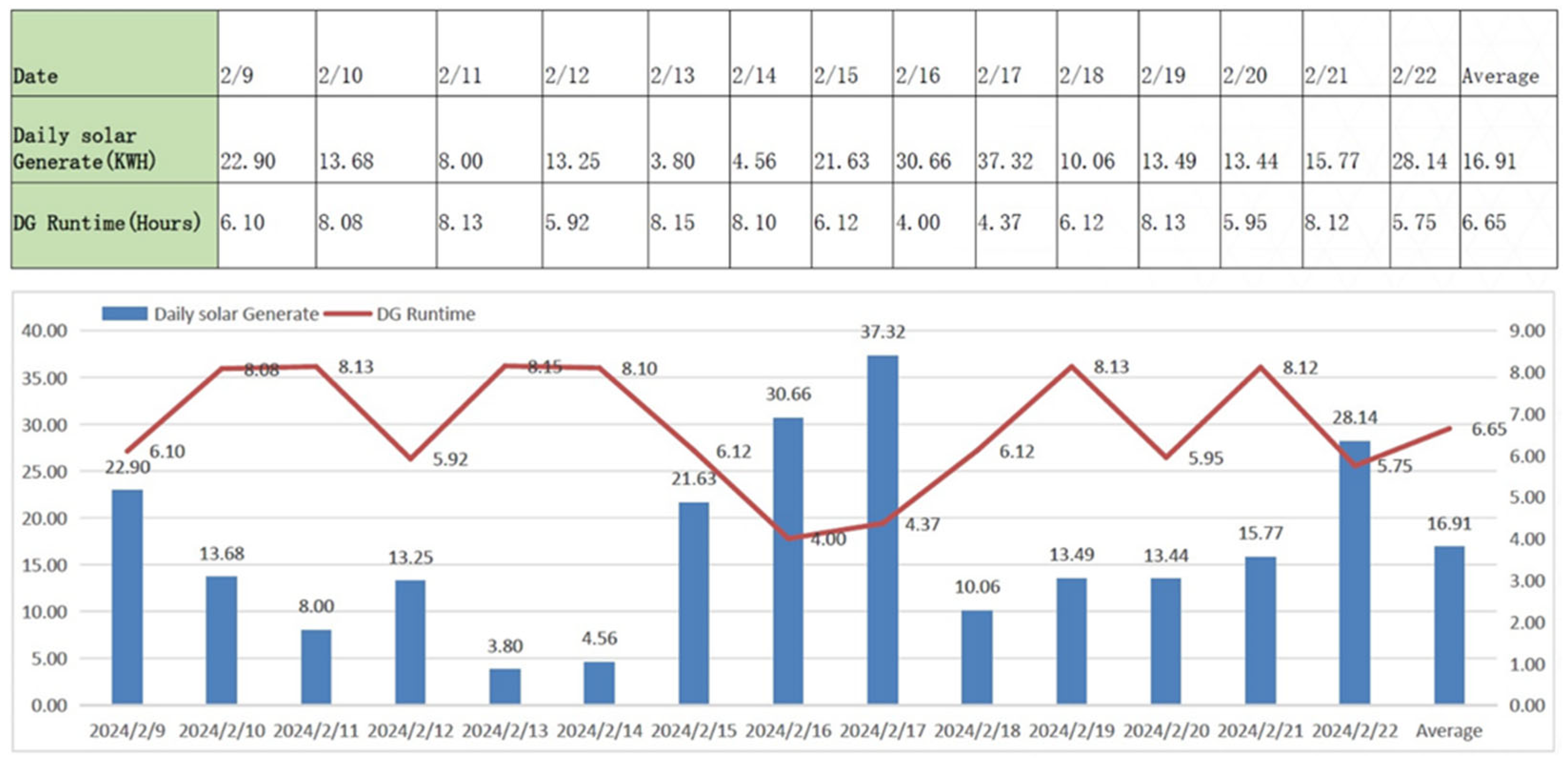
A graphical representation of the base station’s power consumption is shown in Figure 13. The energy is taken from installed PV panels that produce during the day. The unused energy is stored in batteries. When necessary, the batteries, which are pre-charged, are switched on.
Similarly, active equipment has an “Intelligent shutdown” function; it communicates with the power controller and, when certain thresholds are exceeded, gradually turns off individual non-critical modules and functions in order to save energy according to the principles of electromagnetic compatibility.

4. Conclusions

Powering nearby and remote devices requires compliance with the principles of electromagnetic compatibility. For this reason, this article discusses preventive measures to avoid interference and reduce noise.
It is established that, along with the selection of the components of the telecommunication system, the law also requires an uninterrupted power supply. In hard-to-reach places, emergency power outages from the national power grid are possible, especially during seasonal changes and severe weather conditions. That is why the problem was solved by additionally installing PV panels with batteries as a second source. As a third source, according to the norms for category 0, a diesel generator is proposed. The advantages and disadvantages of the three sources are analyzed according to the sustainable development paradigm. An algorithm for switching on the individual devices is proposed, so as to ensure uninterrupted power supply to the individual components of the telecommunication system at safe current and voltage values.
The team believes that by complying with the regulatory norms and properly constructing and installing the proposed components, the system will be able to function without failure for a long period of time with minimal service by workers.

Author Contributions

Conceptualization, I.S. and G.M.; methodology, T.H., O.F. and P.H.; software, P.H., K.G.-E. and B.G.; validation, I.S., G.M. and T.H.; formal analysis, P.H., O.F. and B.G.; investigation, I.S., G.M. and O.F.; resources, I.S., T.H. and K.G.-E.; data curation, P.H. and B.G.; writing—original draft preparation, G.M. and T.H.; writing—review and editing, G.M. and T.H.; visualization, P.H., I.S. and B.G.; supervision, O.F. and K.G.-E.; project administration, G.M. and T.H.; funding acquisition, T.H. and K.G.-E. All authors have read and agreed to the published version of the manuscript.

Funding

This study is financed by the European Union—NextGenerationEU, through the National Recovery and Resilience Plan of the Republic of Bulgaria, project No. BG-RRP-2.013.

Institutional Review Board Statement

Not applicable.

Informed Consent Statement

Not applicable.

Data Availability Statement

Data is contained within the article.

Conflicts of Interest

Ivelin Stoykov is employed by CETIN Bulgaria Ltd. The authors declare no conflict of interest.

References

  1. Crovetti, P.S. Electromagnetic Interference and Compatibility; MDPI: Basel, Switzerland, 2021. [Google Scholar] [CrossRef]
  2. Chinh, Q.D.; Nguyen, B.T. Basics Telecommunication System Covers Working Principles and Emerging Problems. J. Multiapp 2021, 1, 10–16. [Google Scholar] [CrossRef]
  3. Statista. Global Mobile Industry Contribution to GDP 2014–2030. Available online: https://www.statista.com/statistics/1100651/worldwide-mobile-industry-contribution-gdp/ (accessed on 17 February 2025).
  4. Al-Debei, M.M.; Avison, D. Business model requirements and challenges in the mobile telecommunication sector. J. Organ. Transform. Soc. Change 2011, 8, 215–235. [Google Scholar] [CrossRef] [PubMed]
  5. Brasini, T.; Domecq, M.; Iliev, T.B.; Stoyanov, I.; Mihaylov, G.; Beloev, I. On Free-Space Optical Communication as a Backhauls Applications for 5G. In Proceedings of the 2022 International Conference on Communications, Information, Electronic and Energy Systems (CIEES), Veliko Tarnovo, Bulgaria, 24–26 November 2022; pp. 1–4. [Google Scholar] [CrossRef]
  6. Houcine, M.; Mohamed, M.; El Mehdi Ardjoun, S.A.; Mahmoud, M.M.; Telba, A.A.; Denaï, M.; Khaled, U.; Ewais, A.M. Electromagnetic Compatibility Characterization of Start-Capacitor Single-Phase Induction Motor. IEEE Access 2024, 12, 2313–2326. [Google Scholar] [CrossRef]
  7. Ivanova, E.P.; Iliev, T.B.; Stoyanov, I.S.; Mihaylov, G.Y. Evolution of mobile networks and seamless transition to 5G. IOP Conf. Ser. Mater. Sci. Eng. 2021, 1032, 012008. [Google Scholar] [CrossRef]
  8. Jakubowski, K.; Paś, J.; Rosiński, A. The Issue of Operating Security Systems in Terms of the Impact of Electromagnetic Interference Generated Unintentionally. Energies 2021, 14, 8591. [Google Scholar] [CrossRef]
  9. Paving Your Smart Manufacturing Roadmap, TÜV SÜD. Available online: https://www.tuvsud.com/en-us/resource-centre/stories/smart-industry-readiness-index (accessed on 17 February 2025).
  10. Patel, D. Buzz Killer: A Realistic Look at the Challenges Facing DLT in Trade—Trade Finance Global. 2019. Available online: https://www.tradefinanceglobal.com/posts/challenges-dlt-in-trade (accessed on 17 February 2025).
  11. Marvin, A.C. An Introduction to Cost 261 Electromagnetic Compatibility in Complex and Distributed Systems. In Proceedings of the 14th International Zurich Symposium and Technical Exposition on Electromagnetic Compatibility, Zurich, Switzerland, 20–22 February 2001; pp. 1–2. [Google Scholar] [CrossRef]
  12. Masmali, F.; Miah, S.J.; Noman, N. Different Applications and Technologies of Internet of Things (IoT). arXiv 2021. [Google Scholar] [CrossRef]
  13. Aleksieva, V.; Valchanov, H.; Haka, A.; Dinev, D. Model of Controlled Environment based on Blockchain and IoT. In Proceedings of the 2023 4th International Conference on Communications, Information, Electronic and Energy Systems (CIEES), Plovdiv, Bulgaria, 23–25 November 2023; pp. 1–4. [Google Scholar] [CrossRef]
  14. EPAM Startups & SMBs. IoT in Telecom: Use Cases, Benefits, Examples. Available online: https://startups.epam.com/blog/iot-in-telecommunications (accessed on 27 February 2025).
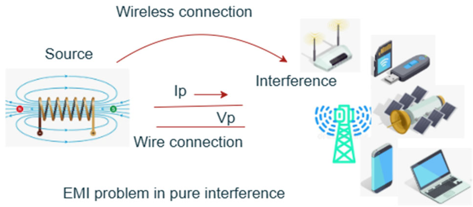
Figure 1. Electromagnetic interference in communications.
Engproc 104 00029 g001
Figure 2. EMI model of telecommunication receiver.
Engproc 104 00029 g002
Figure 3. Grounding the housings of electronic devices by bonding to a common grounded surface.
Engproc 104 00029 g003
Figure 4. Grounding and bonding diagram of (a) Conductor; (b) Power supply.
Engproc 104 00029 g004
Figure 5. (a) Coaxial cable structure; (b) balanced and unbalanced twisted pair.
Engproc 104 00029 g005
Figure 6. Elements and circuits for interference suppression: (a) hybrid circuit with varistor, Zener diode, and passive R and L components; (b) a network filter containing X and Y capacitors and inductors; (c) a simple single throttle.
Engproc 104 00029 g006
Figure 7. General plan of a base station.
Engproc 104 00029 g007
Figure 13. Graph of a base station’s power consumption.
Engproc 104 00029 g013
Disclaimer/Publisher’s Note: The statements, opinions and data contained in all publications are solely those of the individual author(s) and contributor(s) and not of MDPI and/or the editor(s). MDPI and/or the editor(s) disclaim responsibility for any injury to people or property resulting from any ideas, methods, instructions or products referred to in the content.