Proceeding Paper

Modeling and Control of Permanent Magnet Generators with Fractional-Slot Concentrated Windings Working with Active Converters for Wind Power †

by
Hung Vu Xuan
Department of Electrical Engineering, School of Electrical and Electronic Engineering, Hanoi University of Science and Technology, Hanoi City 100000, Vietnam
Presented at the International Conference on Electronics, Engineering Physics and Earth Science (EEPES 2025), Alexandroupolis, Greece, 18–20 June 2025.
Eng. Proc. 2025, 104(1), 26; https://doi.org/10.3390/engproc2025104026
Published: 26 August 2025

Abstract

This paper presents modeling for an external rotor permanent magnet generator (PMG) with fractional-slot concentrated windings working with a power electronic converter in the rotor magnetic field coordinate—the model is also called the DQ model. The model is needed to synthesize controllers of the PMG. Additionally, modeling for an active rectifier of the PMG is also investigated. The models of PMG and the active rectifier with two closed loops, namely the current loop and dc voltage loop, are verified by simulation in Matlab/Simulink. By modeling PMG in the rotor magnetic field coordinate, vector current can be decomposed in two independent currents, namely active current and reactive current. By controlling the active current, active power or electromagnetic torque or DC bus voltage can be controlled. By setting a relevant reactive current, the power factor or reactive power or rotor magnetic flux of PMG can be controlled. Simulation results of control PMG working with an active converter, such as pulse width modulation voltage, current, DC voltage, or power, are reported. The simulation helps to synthesize controllers and improve performances of the PMG working with the converter in wind applications.

1. Introduction

The d-q model is widely used for induction machines and permanent magnet (PM) machines with distributed windings. The d-q model of a PM machine is used as a prerequisite to design the controllers of an active converter (CVT) [1,2,3,4,5,6,7,8]. It is also commonly used for the fast simulation of the performance of a PM machine. Recently, it has been proven that the d-q model is reliable enough for studying voltage and torque performances of PM machines with concentrated windings. However, this type of PM generator (PMG) has less sinusoidal voltage and flux linkage than the one with distributed windings. This paper’s purpose is to comprehensively study the modeling of concentrated winding PM machines working with an active converter in both generator mode and motor mode to design controllers and improve the performance of the PM machine-converter system. In addition, we will develop a fundamental theory to explain the current model in both rotor magnetic field-oriented control (RFOC) and voltage-oriented control (VOC). Thanks to the mathematical model-based control, the current vector is decomposed into active and reactive currents, which are independently controlled. As a consequence, the voltage vector and current are unified and the power factor reaches 1. Therefore, generating power is utilized to the maximum and a minimum power loss is reached.
The stator coordinator is defined as having the α-axis identical to the winding phase a-axis of the natural coordinator a-b-c and the β-axis being perpendicular to the α-axis. Therefore, the stator coordinator is a standstill coordinator. The rotor magnetic field coordinator in the PMG model is defined as having the d-axis (in this case, reactive current) identical to the direction of the vector rotor magnetic field and the q-axis (in this case, active current) perpendicular to the d-axis. Therefore, the rotor field coordinator (RFC) is a rotating coordinator. In the steady state, the dq-coordinator synchronously rotates with the angle speed of the fundamental rotor magnetic field, so that electrical current components in the d and q directions are DC quantities. The RFC-based model of a PM machine is often used for motor control according to the rotor field-oriented control (FOC) method in the pitch drives of a wind turbine or grid-connected generator [9,10,11,12].
Conversely, for the modeling of a pulse width modulation (PWM) AC/DC converter according to the Voltage-Oriented Control (VOC) method, the d-axis (in this case, active current) is identical to the vector voltage, and the q-axis (in this case, reactive current) is perpendicular to the d-axis. Therefore, by controlling the active current, the DC voltage can be controlled, and by controlling the reactive current, the power factor or reactive power can be controlled. The VOC is utilized to control the inverter of the grid side and the electrical generator in the case of generator standing alone.
This paper is organized as follows. Firstly, the d-q models of both PMG and CVT at different coordinates are developed to design controllers and explain the PM machine’s performances and the operating modes, such as maximum torque in motor mode and active and reactive power control in generator mode. Then, the models are simulated in Simulink/Matlab®. Finally, simulation results are used to study performances of the PM machine working with the PWM active rectifier.

2. The d-q Model of the PM Machine

2.1. The d-q Model

We assume that the voltage, current and flux linkage of a PM machine are sinusoidal waves, the magnetic circuit is unsaturated and the PM machine has electrical and mechanical symmetry. A PM machine can be modeled in the d-q coordinator as follows.
Voltage equations of a PM machine in the stator coordinator (α, β):
u s s = R s i s s + d ψ s s d t
in Equation (1), u s s is the stator voltage vector in the stator coordinator; the subscript “s” shows that it is the stator component and the superscript “s” indicates that it is in the stator coordinate. It is similar to stator current vector i s s and stator flux vector ψ s s .
The voltage equation of the PM machine in the rotor field coordinator f(d, q) can be obtained by transforming Equation (1), presented in the stator coordinator, to the d-q coordinator as follows:
u s f = R s i s f + d ψ s f d t + j ω e ψ s f
Note that the formula transforms vector V from the stator coordinate to the rotor magnetic field coordinate, V s f = V s s e j θ , where θ is angle between the d-axis and α-axis and ωe is the angular speed of the rotor magnetic field vector, ωe = dθ/dt.
The stator flux vector in the dq coordinate can be written as
ψ s f = L s i s f + ψ p f
ψ s d = L d i s d + ψ p
ψ s q = L q i s q
In the equations above, Ls is stator inductance and Ld and Lq are, respectively, the direct and quadrature components of Ls.
Equation (4) can be rewritten as
ω e ψ s d = X d i s d + ω e ψ p o r ω e ψ s d = X d i s d + E q
where Xd and Xq are reactance in the d and q direction, respectively.
The relationship between the electromagnetic force and pole magnetic flux can be written as
ψ p   = E q / ω e   = 2   E o / ω e
where ψp is the pole magnetic flux and Eq is the quadrature component of electromotive force vector, and Eo is the RMS of the phase fundamental electromotive force.
Equation (5) can be rewritten as
ω e ψ s q = X q i s q
L d = L a d + L σ
L q = L a q + L σ
where Lad is the d-axis main armature inductance and Lσ is stator leakage inductance. The inductances can be obtained by experiment or FEM computation [13,14,15].
Substituting Equations (3)–(5) in Equation (2) gives the following equations:
u s d = R s i s d + d ψ s d d t ω e L q i s q o r u s d = R s i s d + L d d i s d d t ω e L q i s q
u s q = R s i s q + d ψ s q d t + ω e L d i s d + ω e ψ p o r u s q = R s i s q + L q d i s q d t + ω e L d i s d + ω e ψ p
Equations (11) and (12) are balanced voltage equations in the dq coordinate of a PM machine.
The electromagnetic torque equation can be written as [16,17]
T e = 3 2 p Im { ψ s f * i s f } = 3 2 p ( ψ s d i s q ψ s q i s d ) = 3 2 p ( ψ p i s q + i s d i s q ( L d L q ) )
where Im{·} is a function to obtain the imagined part of a complex number and p is the number of pole pairs.
T e = 3 2 ω e p ( E q i s q + i s d i s q ( X d X q ) )
In Equation (14), the first term of the torque is called “magnet alignment torque”. The second term proportional to (Xd − Xq) is called “reluctance torque”. Eq is the quadrature component of the electromotive force vector.
Electromagnetic power can be calculated as
P e = T e . ω e / p = 2 π f . T e / p = 3 π f ( ψ p i s q + i s d i s q ( L d L q ) ) ,
from pole magnetic flux, dq inductances, and active and reactive current.
Output electrical power can be written as
P o = 3 2 Re ( u s i s * )
where i s * is the conjugate vector of the current vector is, and p is the number of pole pairs.
The motion equation for the motor operating mode can be expressed as
J p d ω e d t = T e T m e c
where Tmec and J are the mechanical torque of the load and inertia moment of the load and rotor, respectively. All the above equations are right for both generator mode and motor mode. However, note that for the generator operating mode, the expression on the right of Equation (17) will be (Tmec − Te). The above differential equations can be solved by the Runge–Kutta method or by building a model in Matlab Simulink or using the S-function in Matlab.

2.2. Simulation Model in Matlab/Simulink®

A model of the PM machine in motor operating mode, built in Simulink/Matlab® from Equations (2)–(5), (12) and (16), is shown in Figure 1.
This model can be used to study the starting of the PM generator and motor operating mode. The input data for this model includes directional inductance Ld, quadrature inductance Lq, phase resistance, flux induced by magnets ψp, pole pairs and the inertia moment of rotor and load. In Figure 1, the input parameters are three-phase voltages, and then they are converted into two-phase voltages in the dq coordinate. The usd and usq are inputs of a current model in the dq coordinate, which is described by Equations (11) and (12). The outputs of the current model are isd and isq, which are then used to calculate electromagnetic torque as (13). Finally, rotor speed is calculated according to (17).
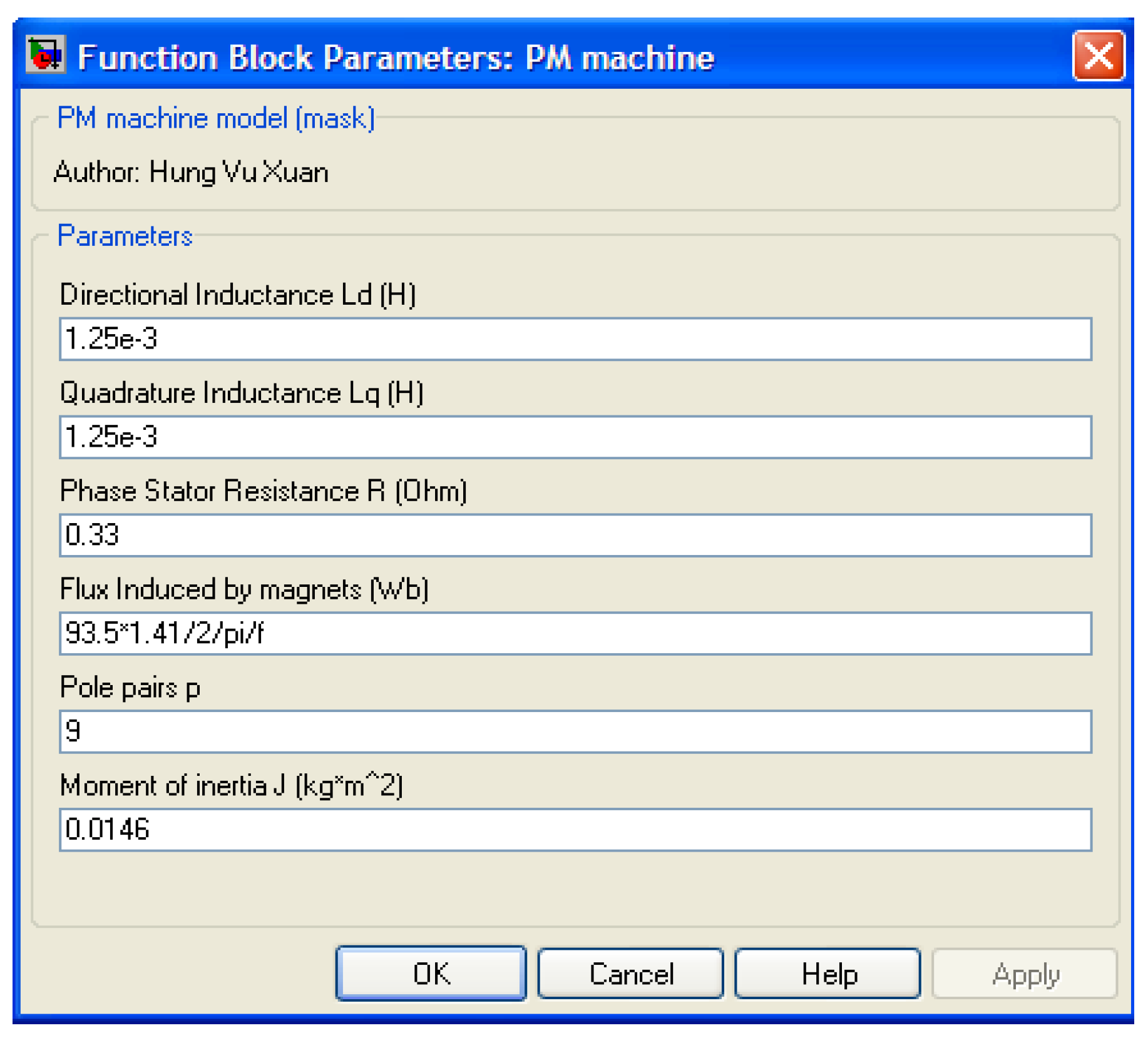
Figure 2 is the interface menu built to enter data of the PM machine. Almost all parameters of the PM machine in Figure 2 have been estimated and validated by experiments, except for the inertia moment, which is an assumption-based calculation. The magnetic flux produced by magnets was calculated and validated using the experimental electromotive force.
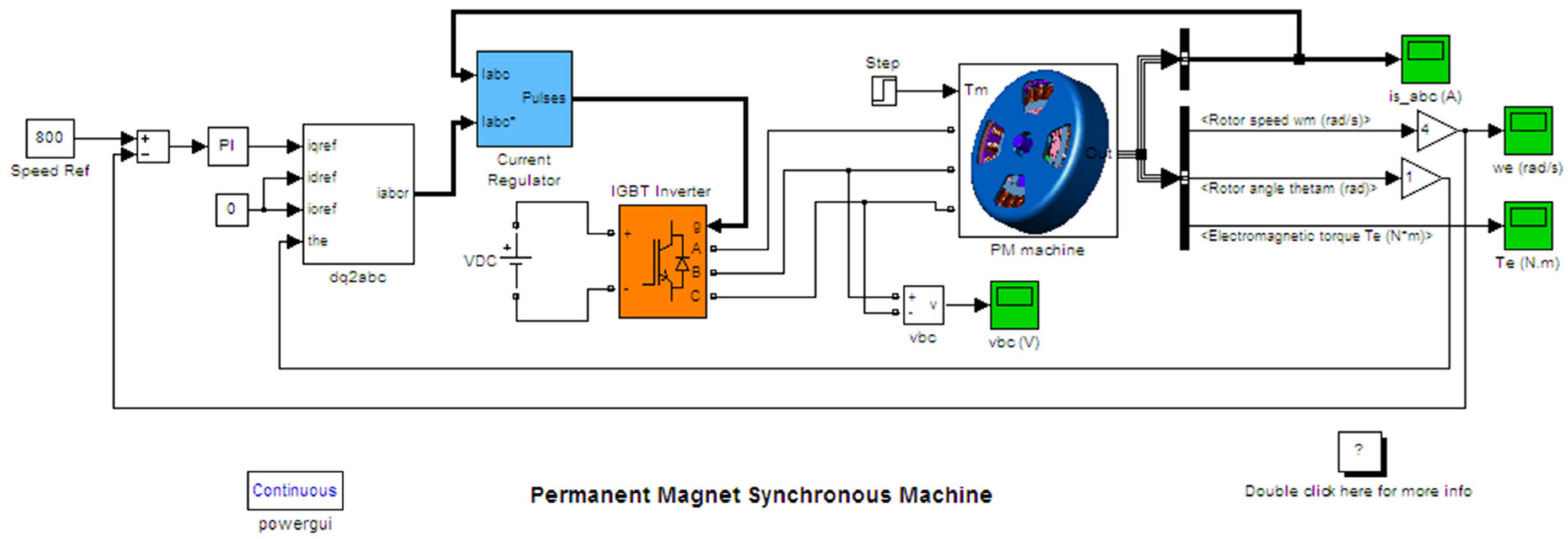
Figure 3 is an example of the simulation of the PM machine working with a rotor field-oriented inverter in wind turbine pitch drive applications. In Figure 3, there are two closed loops; the inner closed loops are dq current loops and the outer closed loop is a speed loop. The PM machine block, which is a submodel, is modeled in the rotor field coordinate as described in Figure 1. With control construction, such as in Figure 3, the rotor speed, electromagnetic torque, and rotor flux of a PM machine with concentrated windings are controlled; the results are quite similar to those of PM machines with distributed windings, which are available in work such as [1,4] so they do not need to be mentioned here again.

3. PM Generator Working with PWM Rectifier with Power Factor Controller

In this section, the modeling of an AC/DC converter with voltage-oriented control (VOC) is investigated. Figure 4 presents a simple equivalent circuit of a PMG working with an active rectifier load. The PMG is replaced with a three-phase electromotive force (EMF) system and inductances including resistances. We assume that the three-phase EMF system is symmetrical, so that the inductance of a phase is identical: La = Lb = Lc = L and resistance Ra = Rb = Rc = R. The dropped voltage on the switcher is ignored and the commutation of switches is neglected.

3.1. Mathematical Model for the PWM Rectifier in the (a, b, c) Frame Reference

The voltage equation for phase a can be written as [1,2,3,4,5,6,7,8]
L d i a d t + R i a = e a u a n
u a n = u a o + u o n
where the subscripts of voltages correspond to nodes in Figure 4; n is the neutral point of the generator, and o is the ground point of the DC bus.
Sa is defined as the switching function of a phase switch. When the upper switch T1 is on, then Sa = 1 (and T4 is off), and point “a” on Figure 4 is connected to point “d”, so that a ≡ d. Thus, the voltage uao = Vdc = SaVdc. If T1 is off and T4 is on, then Sa = 0 and point a is connected to point “o”, and a ≡ o; thus, the voltage uao = 0 = SaVdc. Similarly, the switching functions for Sb and Sc are also defined for phases b and c. The input voltage of the rectifier is defined as ua   uao, ub   ubo, uc   uco. Therefore, the relationship between the input voltage of the rectifier, switching function and DC voltage can be written as
u a = S a V d c ; u b = S b V d c ; u c = S c V d c .
For the three-wiring system, we always have
ia + ib +ic = 0 and ea + eb + ec = 0,
which means that the total three-phase current as well as the total three-phase symmetrical EMF equals zero.
For phase a, substituting (19) and (20) into (18), and similarly doing the same for phases b and c, the voltage equations can be rewritten as
L d i a d t + R i a = e a ( S a V d c + u o n )
L d i b d t + R i b = e b ( S b V d c + u o n )
L d i c d t + R i c = e c ( S c V d c + u o n )
where uon is voltage between the neutral point of source n and the ground of the DC bus.
The voltage uon can be obtained by adding (22), (23) and (24) and considering (21); therefore, the voltage uon can be written as
u o n = V d c 3 k = a , b , c S k .
Substituting (25) into Equations (22)–(24), the voltage equations can be rewritten as
L d i a d t + R i a = e a ( 2 3 S a S b 3 S c 3 ) V d c
L d i b d t + R i b = e b ( 2 3 S b S a 3 S c 3 ) V d c
L d i c d t + R i c = e c ( 2 3 S c S b 3 S a 3 ) V d c .
For more compactness, Equations (22)–(24) can be rewritten in the matrix form as
L d i s d t + R i s = e s u r
In Equation (29), ur is input voltage vector of the rectifier. It can be expressed as
u r = ( S . V d c + D . u o n )
where es is the electromotive force vector, ur is the input voltage vector of the rectifier—which is the difference in the voltage vector between the input of rectifier and point o—and
is = [ia, ib, ic]’; es = [ea, eb, ec]’; ur = [ua, ub, uc]’; S= [Sa, Sb, Sc]’; D = [1, 1, 1]’. Note that the sign ( ‘ ) denotes for the transpose operator of a matrix.
Applying Kirchhoff’s law for node d in Figure 4, the direct current idc can be written as
i d c = S a i a + S b i b + S c i c .
The current ic through the DC capacitor Cd can be written as
i c = C d d V d c d t = i d c i l or   C d d V d c d t = S a i a + S b i b + S c i c i l .
The instantaneous apparent power s of the rectifier is defined as
s ( t ) = u a i a + u b i b + u c i c + j 1 3 [ ( u b u c ) i a + ( u c u a ) i b + ( u a u b ) i c ] .
The active power p and reactive power q are defined as
p ( t ) = u a i a + u b i b + u c i c
q ( t ) = 1 3 [ ( u b u c ) i a + ( u c u a ) i b + ( u a u b ) i c ] .

3.2. The Mathematic Model for the PWM Rectifier in the (d-q) Coordinator

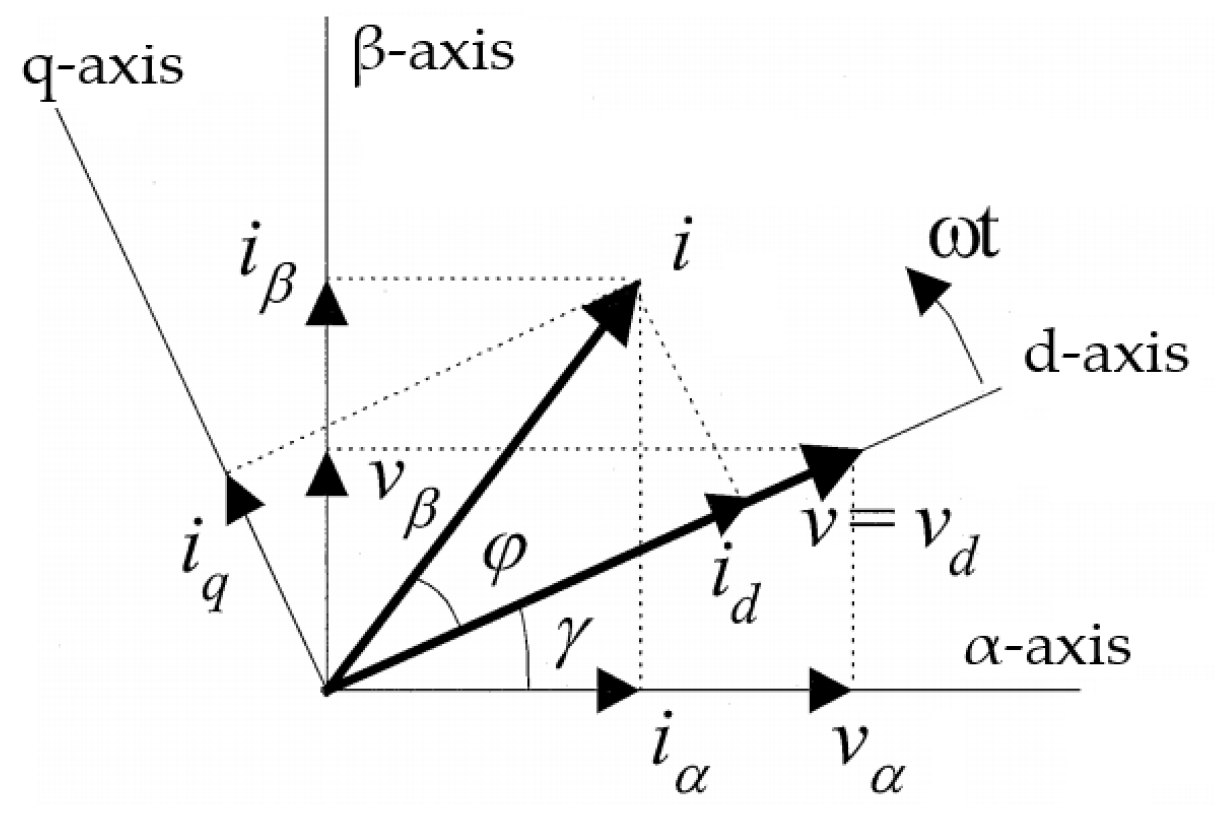
We assume that the voltages and currents of phases a, b and c are sinusoidal. By using Park’s transformation, Equation (29), written in the stationary (a, b, c) reference frame, is transformed into (36) in the rotating f(d, q) coordinate. The d-axis coincides with the electromotive force vector (EMF) of the generator and the q-axis is perpendicular to the d-axis, as shown in Figure 5. The d-q coordinator rotates with an angle speed ωe = 2πf, where f is the frequency of the internal voltage of the generator. Note that the d-q coordinator described in this section is oriented according to the EMF vector so that it is different to the d-q rotating magnetic field coordinator of the permanent magnet machine [1,2,3,4].
The voltage equation of the PWM rectifier in the q-d coordinator can be described as
L d i s f d t + j ω e L i s f + R i s f = e f u r f .
The vector Equation (36) is separated into the components in the d-axis and q-axis:
L d i d d t = e d R i d + ω e L i q u r d
L d i q d t = e q R i q ω e L i d u r q
The input power of the rectifier can be expressed as
p t = 3 2 Re ( u r f i r f * ) = 3 2 u r d i d + u r q i q
q t = 3 2 Im ( u r f i r f * ) = 3 2 u r d i q + u r q i d
The d-axis coincides with the internal voltage vector (so-called Voltage Oriented Control method—VOC) so that the q component of voltage uq is equal to zero in steady state operation. The q-current component iq is able to be controlled by the current controller so that the power factor can also be controlled. If the q-current is zero, the vector voltage and vector current will be unified, so that the power factor will be equal to 1. For the generator, the angle between the electromotive force and the current will not be measured directly, but it can estimate from the measured voltage and measured current.
Vector u r f is defined as follows
u r ' f = u r d ' + j u r q '
u r d ' = L d i d d t + R i d
u r q ' = L d i q d t + R i q .
Thus, substituting (42) and (43) into (37) and (38), we obtain
u r d = u r d ' + ω e L i q + e d
u r q = u r q ' ω e L i d + e q
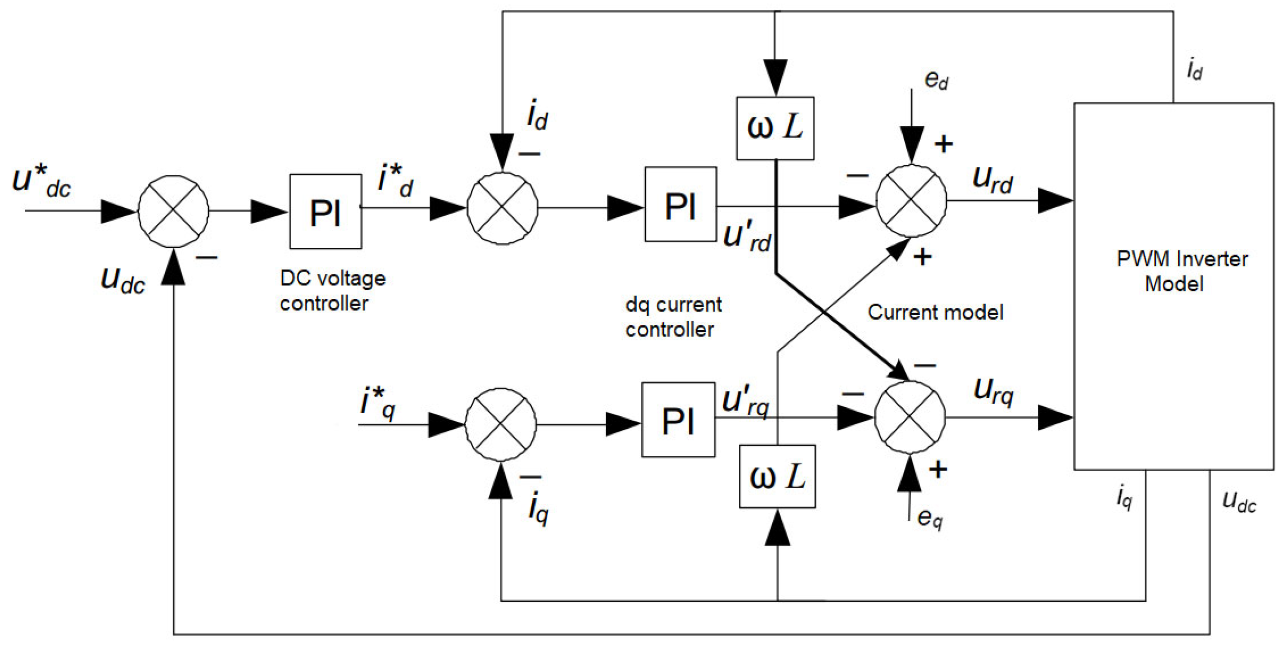
From Equations (44) and (45), the control diagram of a PWM rectifier, including the DC voltage closed loop and the current closed loops, can be presented as in Figure 6. In Figure 6, the DC voltage at the DC bus is controlled by the DC voltage controller. The output of the voltage controller is the setting value id* of the current control loop. The dq current model is formed from Equations (44) and (45). The vector current is decomposed into two separated currents, id and iq. The inputs of the current model have set values of id* and iq*. There are two current controllers for controlling the active and reactive current. The outputs of the current model have set dq voltages of urd and urq, which are the reference voltage for pulse width modulation (PWM). For few kilowatts PMM, the transient time for current response is normally a few milliseconds only, which is much quicker (normally at least 2 times quicker) than the transient time of the outer DC voltage loop. Therefore, the parameters of current controllers are key for the stability and control quality of the system, as will be discussed in a later section. If the set iq* current is zero and there is a quick response in terms of current, the generator voltage and current vector will be in the same phase and the power factor will be 1.

3.3. Simulation PWM Rectifier

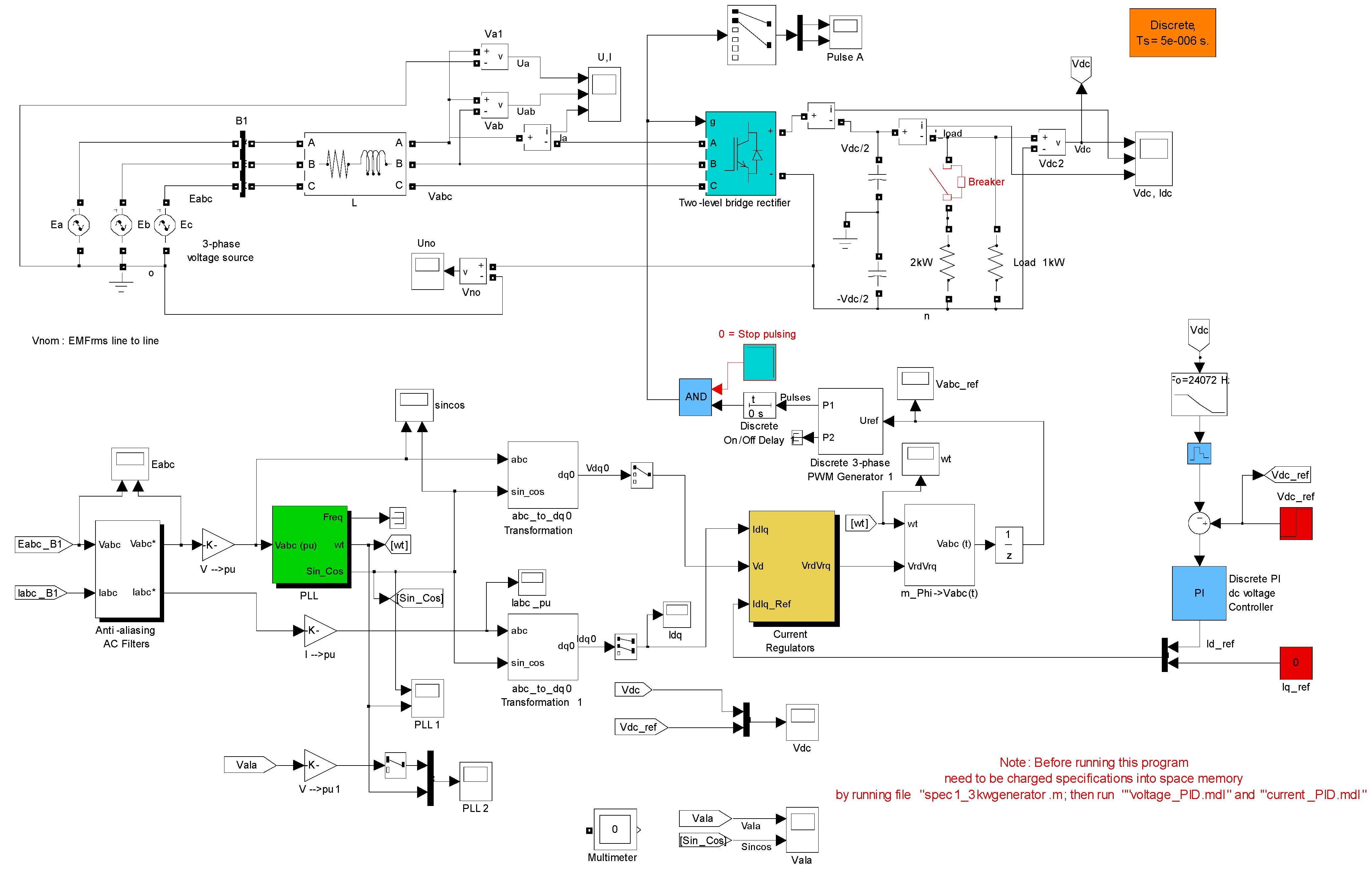
Figure 7 presents the control construction of an active rectifier for a generator in standalone mode. The measured DC voltage is used as a feedback signal for the DC voltage control loop. The currents id and iq are independently controlled together. Three-phase currents iabc of the generator are measured, and are then converted into αβ components in a stationary coordinate using Clarke’s transformation and dq current components in RFC using Park’s transformation, which are used for current signal feedback in current control loops. For coordination conversion from the abc coordinate to the dq coordinate, the θ angle is determined by using Phase-Locked Loop (PLL). The input of the PLL block is from the generator three-phase voltage uabc, which is measured before inductive filtering. It is worth mentioning that for better performance in terms of maximum generated power and eliminating inductive hard filter but with more complications, the generator three-phase voltage and current are measured. After that, the fundamental voltage and current are obtained via a software filter, and finally electromotive forces (EMFs) are calculated from the voltage-balanced equation. The calculated EMFs are used as the input of the PLL block. The structure and parameters of the PLL are determined as in [18,19,20,21].
The main parameters concerning DC capacitor, PMM inductance, rated no-load voltage (EMF), switching frequency and sampling time for simulation in Figure 8, Figure 9, Figure 10 and Figure 11 are as follows:
  • Capacitor: C = 1.8 mF;
  • Phase inductance of PM machine: L = 1.25 mH;
  • Phase resistance of PM machine: R = 0.33 Ω;
  • Line–line electromotive force of PM machine at 3000 rpm: EMF = 162 V;
  • Carrier frequency or switching frequency: fc = 51 * f = 51 * 472 = 24,072 Hz;
  • Sampling time and sampling frequency: Ts = 5 μs, fs =1/Ts = 200 kHz.
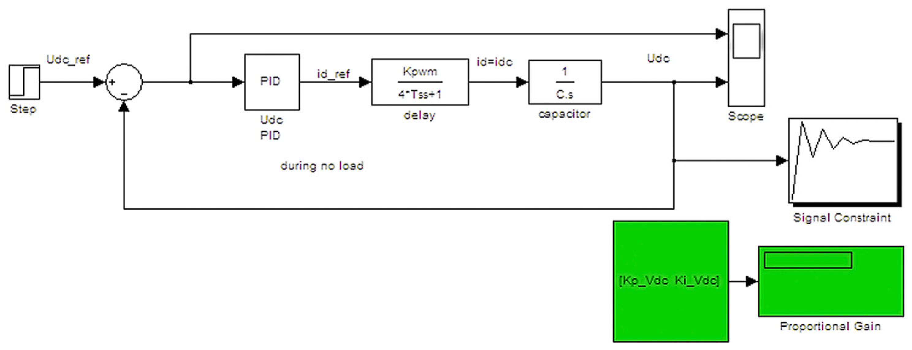
In order to determine the parameters of the current controllers and DC voltage controller, a model for each closed loop must be defined. Figure 8 is a closed loop for finding the parameters of the DC voltage controller, in which PWM is replaced by the first-order transfer function and the control object of the capacitor block of the DC bus. The delay time constant of the PWM transfer function became four times bigger than the sampling time. The amplifier constant of the PWM transfer function is equal to 1, meaning that the PWM output voltage can be mapped 1 to 1 on amplitude, but the delay time is four cycles of sampling time.
Figure 9 is a closed loop for finding the parameters of the current controller. The control object of the electrical current loop involves generator winding resistance and inductance. Therefore, the control object is the first-order transfer function, in which the amplifier and time constant are calculated from the generator resistance and inductance. A delay time block with a delay time double the sampling time is inserted between the current controller and its control object. Figure 10 shows the detail of PI current controllers implemented in Simulink/Matlab®. The parameters of controllers are determined by using the PID auto-tune tool in Matlab when running control loops in Figure 8 and Figure 9. The determined parameters of the controllers will be used in a whole simulation of the PWM converter–PM generator system, as described in Figure 11. Figure 11 shows the whole simulation blocks in Matlab Simulink, including the models of the generator, PWM converter, controllers, and DC load, the measurement of the DC voltage, three-phase generator voltage and three-phase current, and PLL for determining synchronous θ angle, which is used to convert the generator three-phase current iabc to two-phase idq. The PWM block is implemented by comparing the carrier signal to three-phase reference signals, which are obtained from outputs of the current controller after converting. The output signals of the PWM block are used to control the switchers of the converter. The PWM signals to control the upper-leg switcher and lower-leg switcher are opposites. Additionally, a dead time is taken into account to prevent short-circuiting of the DC bus and to protect the switchers from short-circuit current.
Figure 8. Closed loop for finding parameters of PI dc-voltage controller using PID tune tool in Matlab.
Engproc 104 00026 g008
Figure 9. Closed loop for finding parameters of PI current controller using PID tune tool in Matlab.
Engproc 104 00026 g009
Figure 10. Structure of current controller in Simulink.
Engproc 104 00026 g010
Figure 11. Simulation of whole generator-PWM rectifier system with power factor control.
Engproc 104 00026 g011
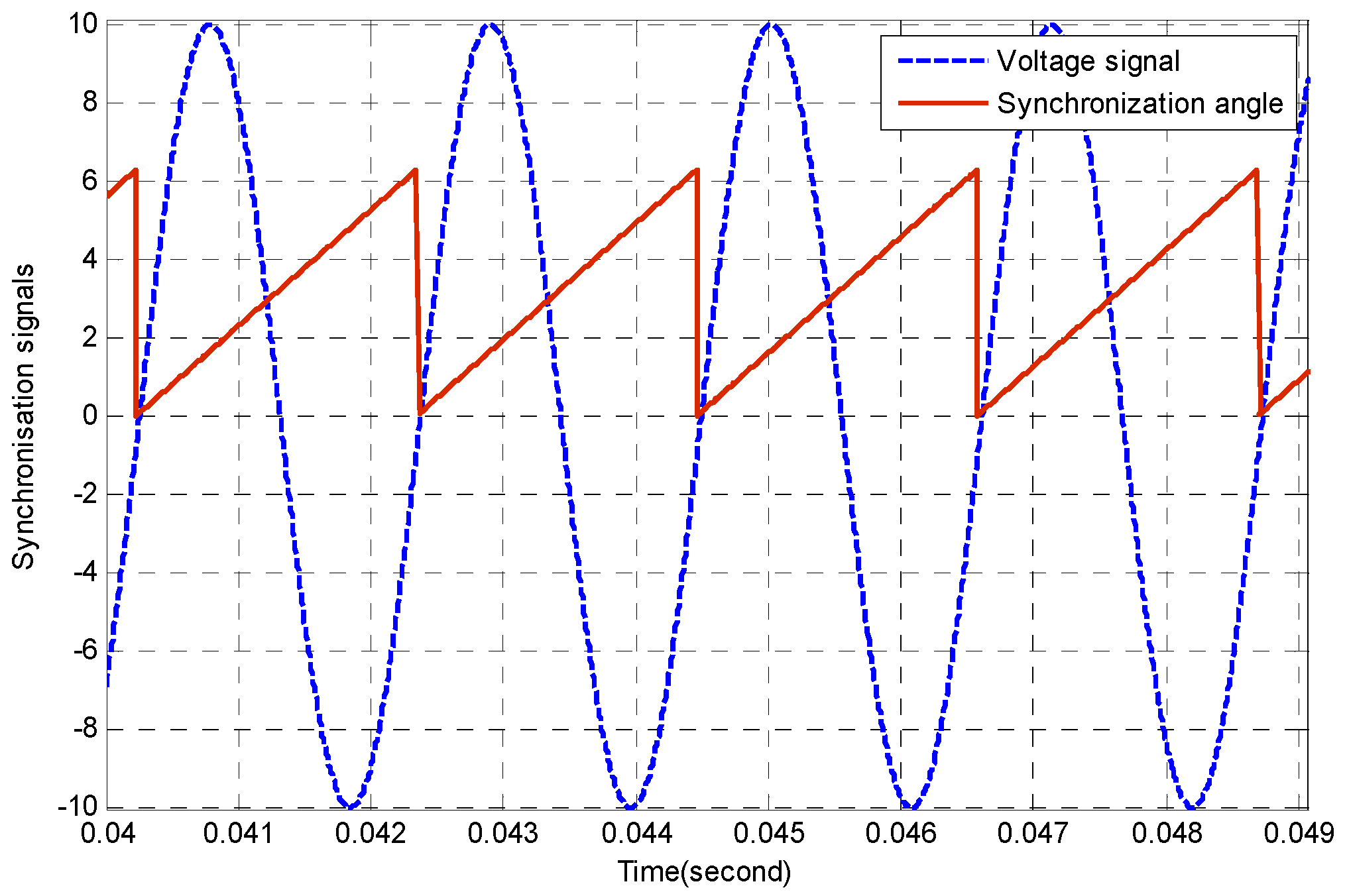
It can be seen from Figure 12 that the θ angle, output signal of the PLL block and a triangle signal synchronize to the voltage signal of phase a and vary from 0 to 2π in one voltage cycle. This figure also shows that the PLL block works well to meet the requirements for synchronization. This requirement is crucial for voltage-oriented control.
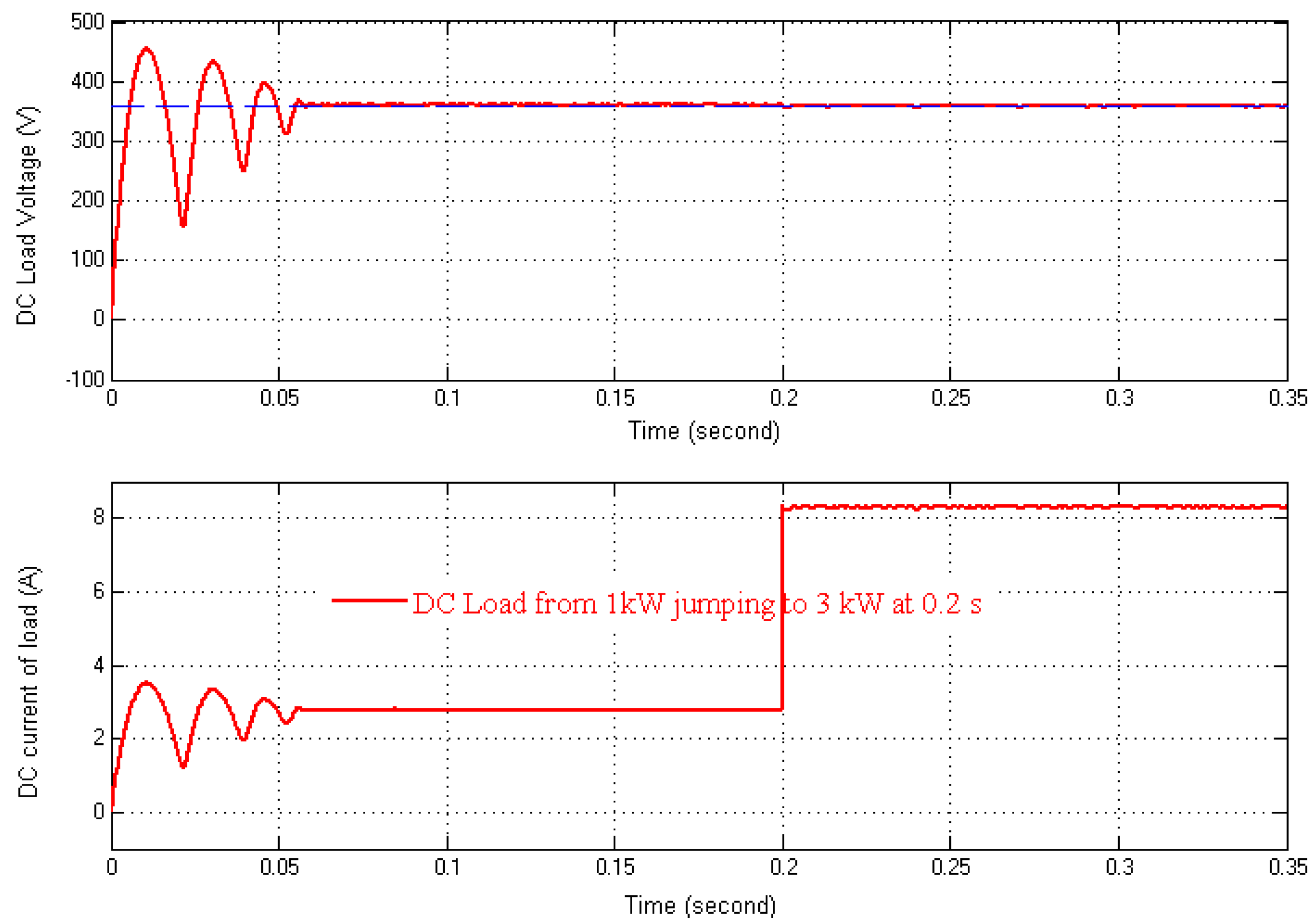
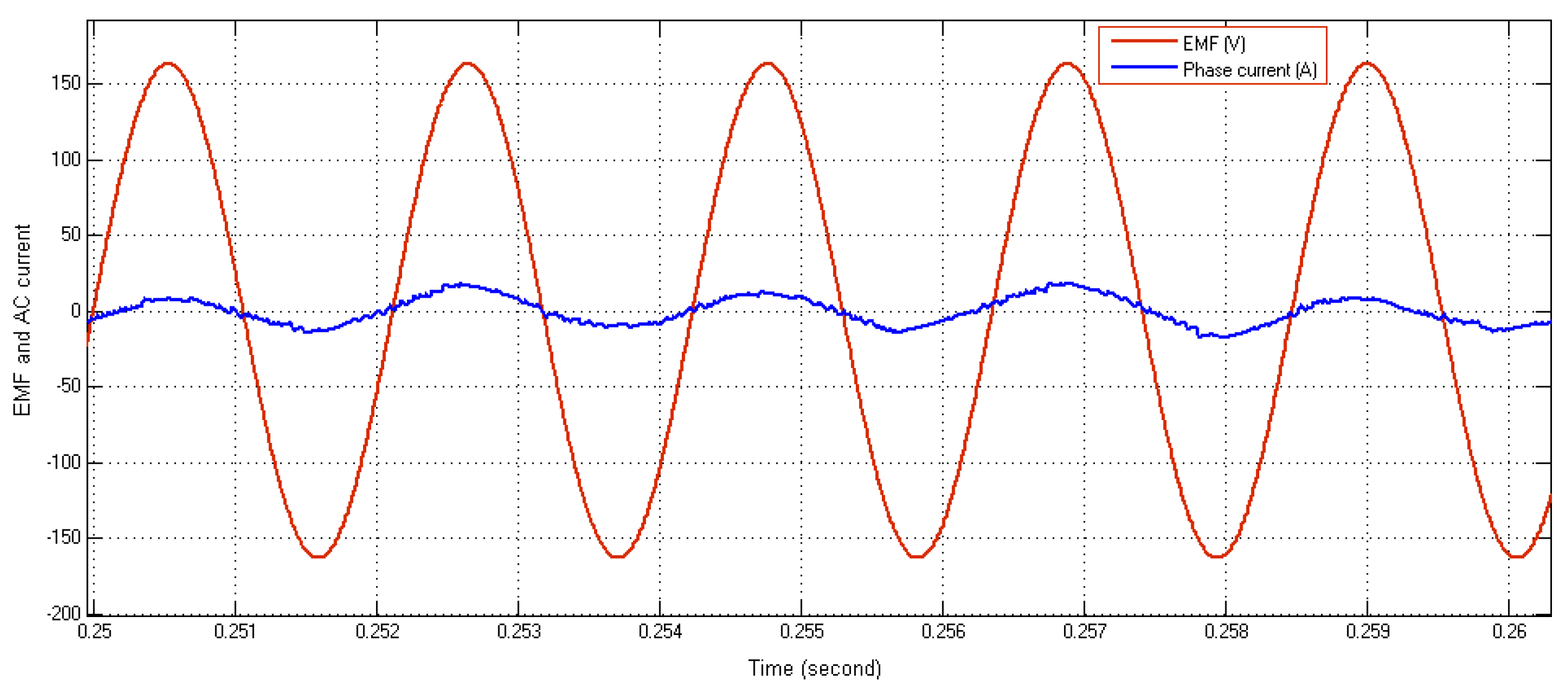
Figure 13, Figure 14 and Figure 15 show some simulation results of the PWM converter–PM generator system. Figure 13 shows the DC voltage and current during charging and steady state. It also shows that DC voltage is kept constant and follows the setting value with negligible error in steady state, even with load jumping from 1 kW to 3 kW at the moment of 0.2 s in the simulation. It can be seen from Figure 14 that the phase EMF and phase current are in phase unity. Figure 15 shows the PWM voltage and current of the active converter. All simulation results prove that the parameters of current and dc voltage controls are well estimated.

4. Conclusions

This paper has presented mathematic models for both a PM generator with fractional-slot concentrated windings and an active rectifier in the dq coordinate. The model was built, simulated and verified in Simulink Matlab to prove the accuracy of the developed model. The effective method to define parameters of the current controller and DC voltage controller were presented. The simulation result with real specifications of a real external PM generator with concentrated windings show that the current response and DC voltage also follow the setting values. Thanks to the quick responses of the dq current, the phases of generator voltage and current are unified or show a generator power factor of 1.

Funding

This research was funded by the Hanoi University of Science and Technology (HUST) under project number T2020-SAHEP-002.

Institutional Review Board Statement

Not applicable.

Informed Consent Statement

Not applicable.

Data Availability Statement

Data will be available based on request.

Conflicts of Interest

The authors declare no conflicts of interest.

Abbreviations

The following abbreviations are used in this manuscript:
CVTConverter
PMGPermanent Magnet Generator
PMMPermanent Magnet Machine
PWMPulse Width Modulation
PLLPhase-Locked Loop
VOCVoltage-Oriented Control
FOCField-Oriented Control
RFCRotor Field Coordinator

References

  1. Kang, S.-P.; Kim, D.-Y.; Kim, J.-M. Enhanced Voltage Sensorless Control for a PWM Converter with DSOGI-FLL Under Grid Disturbances. Energies 2025, 18, 2199. [Google Scholar] [CrossRef]
  2. Malinowski, M.; Kazmierkowski, M.P.; Hansen, S.; Blaabjerg, F.; Marques, G.D. Virtual-Flux-Based Direct Power Control of Three-Phase PWM Rectifiers. IEEE Trans. Ind. Appl. 2001, 37, 1019–1027. [Google Scholar] [CrossRef]
  3. Noguchi, T.; Tomiki, H.; Kondo, S.; Takahashi, I. Direct Power Control of PWM Converter without Power-Source Voltage Sensors. IEEE Trans. Ind. Appl. 1998, 34, 473–479. [Google Scholar] [CrossRef]
  4. Malinowski, M.; Kazmierkowski, M.P.; Trzynadlowski, A.M. A Comparative Study of Control Techniques for PWM Rectifiers in AC Adjustable Speed Drives. IEEE Trans. Power Electron. 2003, 18, 1390–1396. [Google Scholar] [CrossRef]
  5. Alonso-Martínez, J.; Carrasco, J.E.-G.; Arnaltes, S. Table-Based Direct Power Control: A Critical Review for Microgrid Applications. IEEE Trans. Power Electron. 2010, 25, 2949–2961. [Google Scholar] [CrossRef]
  6. Sato, A.; Noguchi, T. Voltage-Source PWM Rectifier–Inverter Based on Direct Power Control and Its Operation Characteristics. IEEE Trans. Power Electron. 2011, 26, 1559–1567. [Google Scholar] [CrossRef]
  7. Singh, B.; Singh, B.N.; Chandra, A.; Al-Haddad, K.; Pandey, A.; Kothari, D.P. A Review of Single-Phase Improved Power Quality AC-DC Converters. IEEE Trans. Ind. Electron. 2003, 50, 962–981. [Google Scholar] [CrossRef]
  8. Singh, B.; Singh, B.N.; Chandra, A.; Al-Haddad, K.; Pandey, A.; Kothari, D.P. A Review of Three-Phase Improved Power Quality AC-DC Converters. IEEE Trans. Ind. Electron. 2004, 51, 641–660. [Google Scholar] [CrossRef]
  9. Rajendran, S.; Diaz, M.; Cárdenas, R.; Espina, E.; Contreras, E.; Rodriguez, J. A Review of Generators and Power Converters for Multi-MW Wind Energy Conversion Systems. Processes 2022, 10, 2302. [Google Scholar] [CrossRef]
  10. Chimurkar, P.; Kothavade, P. A Review of Different Power Converter Topologies for PMSGs Wind Turbine. In Proceedings of the 2016 International Conference on Communication and Electronics Systems (ICCES), Coimbatore, India, 21–22 October 2016; pp. 1–6. [Google Scholar]
  11. Hannan, M.A.; Al-Shetwi, A.Q.; Mollik, M.S.; Ker, P.J.; Mannan, M.; Mansor, M.; Al-Masri, H.M.K.; Mahlia, T.M.I. Wind Energy Conversions, Controls, and Applications: A Review for Sustainable Technologies and Directions. Sustainability 2023, 15, 3986. [Google Scholar] [CrossRef]
  12. Baroudi, J.A.; Dinavahi, V.; Knight, A.M. A Review of Power Converter Topologies for Wind Generators. In Proceedings of the IEEE International Conference on Electric Machines and Drives, San Antonio, TX, USA, 15 May 2005; pp. 458–465. [Google Scholar]
  13. Vu Xuan, H.; Ani, S.O.; Lahaye, D.; Polinder, H.; Ferreira, J.A. Validation of Non-Linear Dynamic FEM Model for Design of PM Machines with Concentrated Windings in Ship Application. In Proceedings of the 2011 14th European Conference on Power Electronics and Applications, Birmingham, UK, 30 August–1 September 2011; Available online: https://ieeexplore.ieee.org/abstract/document/6020450 (accessed on 6 June 2025).
  14. Vu Xuan, H. Modeling of Exterior Rotor Permanent Magnet Machines with Concentrated Windings. Dissertation (TU Delft). Ph.D. Thesis, Delft University of Technology, Delft, The Netherlands, September 2012. [Google Scholar]
  15. Vu Xuan, H.; Lahaye, D.; Polinder, H.; Ferreira, J.A. Influence of Stator Slotting on the Performance of Permanent-Magnet Machines With Concentrated Windings. IEEE Trans. Magn. 2013, 49, 929–938. [Google Scholar] [CrossRef]
  16. Shivarudraswamy, R.; Tangi, S.; Kaup, A. Advancements in PMSM-Based Commercial Fan Control: Hardware, FOC Implementation, and Performance Evaluation. Eng. Proc. 2024, 70, 49. [Google Scholar] [CrossRef]
  17. Ahmad, M.S.; Ishak, D.; Leong, T.T.; Mohamed, M.R. Analytical Subdomain Model for Double-Stator Permanent Magnet Synchronous Machine with Surface-Mounted Radial Magnetization. Eng. Proc. 2021, 12, 37. [Google Scholar] [CrossRef]
  18. Debdouche, N.; Benbouhenni, H.; Deffaf, B.; Anwar, G.; Zarour, L. Predictive Direct Power Control with Phase-Locked Loop Technique of Three-Level Neutral Point Clamped Inverter Based Shunt Active Power Filter for Power Quality Improvement. Int. J. Circuit Theory Appl. 2024, 52, 3306–3340. [Google Scholar] [CrossRef]
  19. He, Z.; Shinshi, T. Torque Regulation Theory and Sensorless Control Technology for Unipolar Salient Synchronous Permanent Magnet Motor Based on Unified Models. IEEE Trans. Power Electron. 2025, 40, 5672–5684. [Google Scholar] [CrossRef]
  20. Peng, L.; Fu, Z.; Xiao, T.; Qian, Y.; Zhao, W.; Zhang, C. An Improved Dual Second-Order Generalized Integrator Phased-Locked Loop Strategy for an Inverter of Flexible High-Voltage Direct Current Transmission Systems under Nonideal Grid Conditions. Processes 2023, 11, 2634. [Google Scholar] [CrossRef]
  21. Xuan, H.V.; Duc, H.V. Design and Comparison of Control Methods for Grid-Connected Solar Converters. In Proceedings of the 2024 5th International Conference on Communications, Information, Electronic and Energy Systems (CIEES), Veliko Tarnovo, Bulgaria, 20–22 November 2024; pp. 1–10. [Google Scholar]
Figure 1. Model of the PM machine simulated in Matlab/Simulink®; inputs of the model are uabc, and outputs of the model are mechanical angle speed ωm, current iabc, and electromagnetic torque Te.
Engproc 104 00026 g001
Figure 2. Interface to input specifications of the PM machine.
Engproc 104 00026 g002
Figure 3. PM machine controlled by the rotor magnetic field-oriented inverter simulated in Simulink/Matlab; the outer loop is the speed loop and the inner loops are dq current loops. PM machine’s block: inputs of the model are three-phase voltage uabc and outputs of the model are mechanical angle speed ωm, current iabc, and electromagnetic torque Te.
Engproc 104 00026 g003
Figure 4. PMG working with an active rectifier; subscripts such “a”, “b” and “c” are, respectively, representative of the corresponding phases.
Engproc 104 00026 g004
Figure 5. Vector diagram and relationship of dq and stator coordinator.
Engproc 104 00026 g005
Figure 6. Closed loops of VOC-PWM rectifier based on VOC method; outer loop is DC voltage, inner loops are dq current loops.
Engproc 104 00026 g006
Figure 7. Principle of the PWM rectifier with reactive power control. Note that the d-q coordinator described in this figure is different from the d-q rotating magnetic field coordinator of the permanent magnet machine.
Engproc 104 00026 g007
Figure 12. Voltage signal of phase a and θ angle for coordinate transformation.
Engproc 104 00026 g012
Figure 13. DC voltage and current during charging and steady-state. Upper part of the figure shows DC voltage, the blue curve is the setting value, the red curve is the feedback value; lower part of the figure is DC current with loads 1 kW and 3 kW.
Engproc 104 00026 g013
Figure 14. Phase EMF and phase current with unity power factor.
Engproc 104 00026 g014
Figure 15. Line-line voltage uab and phase current of the rectifier in steady-state with a closed look.
Engproc 104 00026 g015
Disclaimer/Publisher’s Note: The statements, opinions and data contained in all publications are solely those of the individual author(s) and contributor(s) and not of MDPI and/or the editor(s). MDPI and/or the editor(s) disclaim responsibility for any injury to people or property resulting from any ideas, methods, instructions or products referred to in the content.