1. Introduction
Pollution, as well as the improvement of wastewater quality, is an issue of contemporary relevance. The primary method for addressing this problem is the treatment of industrial wastewater, which is currently widely applied. For the purification of wastewater, i.e., its treatment with the aim of destroying or removing harmful substances, various methods and treatment facilities are employed depending on its composition. Mechanical purification is generally used to separate insoluble mineral and organic impurities, with conventional quiescent settling being the most prevalent method for mechanical (secondary) treatment. Settling tanks are an integral part of every wastewater treatment plant.
Extreme environmental pollution is one of the most pressing global issues facing humanity today. The natural environment is progressively deteriorating, and ecological systems are struggling to cope with the impact of anthropogenic activities, rendering the atmosphere’s capacity for self-regulation impossible [
1]. With infrastructure and regulatory development falling behind the rapid population expansion and urbanisation, the management of industrial wastewater has become increasingly challenging in many countries [
2]. Major cities have begun to recognise the need to reduce the number of pollutants found in water.
Based on the reviewed and analysed literature, it was established that industrial water consumption is 3–4 times higher than domestic consumption. Industrial wastewater is one of the major contributors to water resource pollution, posing a significant threat to the environment and the health of living organisms [
3,
4]. Along with the growing demand for advancement in the fields of engineering and science, the treatment of industrial wastewater has emerged as a critical and highly relevant topic. In light of the ongoing global environmental debate regarding the conservation of natural water resources and their eventual reuse, the related institutions are actively implementing measures to reduce pollution and protect the environment with respect to wastewater.
Every hour, factories, plants and enterprises are discharging waste into the environment, pouring vast amounts of wastewater directly into rivers and oceans on a regular basis. The consequences are profound, inflicting severe damage to the marine environment and fisheries, with the water conservation efforts progressing slowly amid growing public concerns over an impending global water shortage [
5].
A key strategy in safeguarding water sources is effective wastewater management, viewed as the collection, treatment and reuse of wastewater. As wastewater treatment is a procedure dependent on numerous physical and chemical factors, it is imperative to make adequate provisions for the potential changes in wastewater treatment plants. While treated municipal wastewater does have its limitations, it remains a viable resource for deployment in a range of industries, including agriculture [
6].
Previous research has predominantly focused on sedimentation rate models of secondary settling tanks based on the sludge volume index. These models aim to explain sedimentation rate activities and illustrate the relationship between settling characteristics [
7].
Ref [
8] presents the results of an experimental investigation into the clarification of biologically treated domestic wastewater in a settling tank with a suspended sludge layer, determining the optimal range of up-flow velocities that ensure dynamic equilibrium of the suspended layer.
Some authors [
1] have suggested that the radial primary settling tank for municipal wastewater in treatment plants is more effective than other existing designs. Their determinations were based on observations made within one winter month and one summer month. According to their findings, the higher the concentration of solid particles, the more effective the sedimentation. In addition, they recommend the use of coagulants (solutions of iron and aluminium) to improve the efficiency of primary sedimentation.
Other studies [
9] focus on developing a kinetically dependent sedimentation model and a simulation framework to strengthen the treatment efficiency of industrial wastewater in compact systems. They use experimentally determined operating conditions, wastewater characteristics and sludge concentration as parameters to investigate the reaction rate and hydrodynamics for optimising the dimensions of the treatment plant. The study concludes that mechanical and water parameters have a significant effect on the hydrodynamics of the sludge in the sedimentation model.
The empirical studies conducted by Sonal Rajoria et al. [
10] explored the effectiveness of different electrode materials in the electrochemical oxidation process for wastewater treatment, with a clear focus on various electrode materials for industrial wastewater treatment.
Wakeman [
11] notes the sluggish settling rate of particles a few microns in diameter and recommends that they be coagulated for a period of time to increase their effective size and therefore extend the duration for settling. The scientist Nian-Sheng Cheng [
12] developed a new method for estimating the settling velocity of natural sediment particles dispersed in a liquid. Based on the results collected, he found that the power depends on the effective density coefficient of the sediment particles and volume concentration.
Furthermore, Alexandru Constantin et al. [
13] conducted a theoretical study based on CFD analysis for a conventional radio clarifier. Through simulation with ANSYS software, the researchers obtained values for fluid velocity, turbulence intensity and Reynolds number.
Previous research has focused on developing kinetically dependent sedimentation models and simulation frameworks for enhanced wastewater treatment efficiency. Theoretical studies employing CFD analysis for conventional clarifiers have also been performed. However, despite the multitude of studies conducted so far, there remains a notable absence of a proposed three-dimensional model for determining the movement of the solid phase and water within a fluid domain in terms of the influence of the rotating elements, as well as the settling velocity, utilising parameters relative to the sludge volume index. Such a model would prove invaluable to researchers in the relevant field, as well as to manufacturers of radial wastewater settling tanks, granting the opportunity to enhance process optimisation.
2. Materials and Methods
Wastewater treatment, currently the most widespread technique, is the primary means of preventing water pollution. It is therefore necessary to upgrade these practices by implementing effective and sustainable wastewater treatment systems (WWTS).
Due to the integration of energy production and resource recovery during the production of clean water, wastewater treatment facilities have been identified as a crucial component of circular sustainability.
One of the main processes in mechanical purification is sedimentation, which is also one of the most widely recognised methods for efficient wastewater treatment, known for its proven ability to achieve impressive removal rates of 92–95% for settleable solids, 40–60% for total suspended solids and 25–40% for biological oxygen demand (BOD). Sedimentation, constrained by gravitational forces, is a process in which particles with a larger volumetric weight than that of water sink to the bottom of the facility, while lighter particles soar to the surface [
14].
Diverse types of settling tanks are used in practice, corresponding to the performance of the treatment plant, groundwater level, geological conditions and the adopted technological treatment scheme.
It should be noted that the present study is designed to put a special focus on secondary radial settling tanks, which are well suited for medium and large treatment plants and offer a fairly efficient purification process.
In principle, the designs of secondary settling tanks do not differ significantly from those of primary settling tanks. Structurally, the different variations in secondary settling tanks, such as their primary counterparts, fall into three main groups: horizontal, radial and vertical [
15].
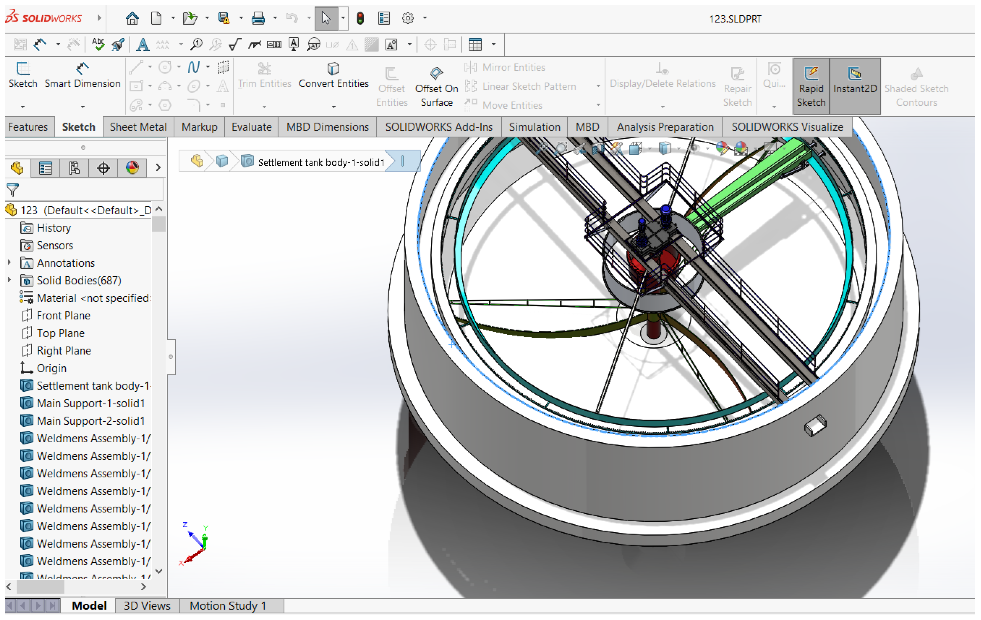
Figure 1 depicts the 3D model of the radial wastewater settling tank designed in the SolidWorks software environment. This reinforced concrete structure features a circular cross-section with a diameter ranging from 12 to 60 m and a working depth of 1.5–5 m.
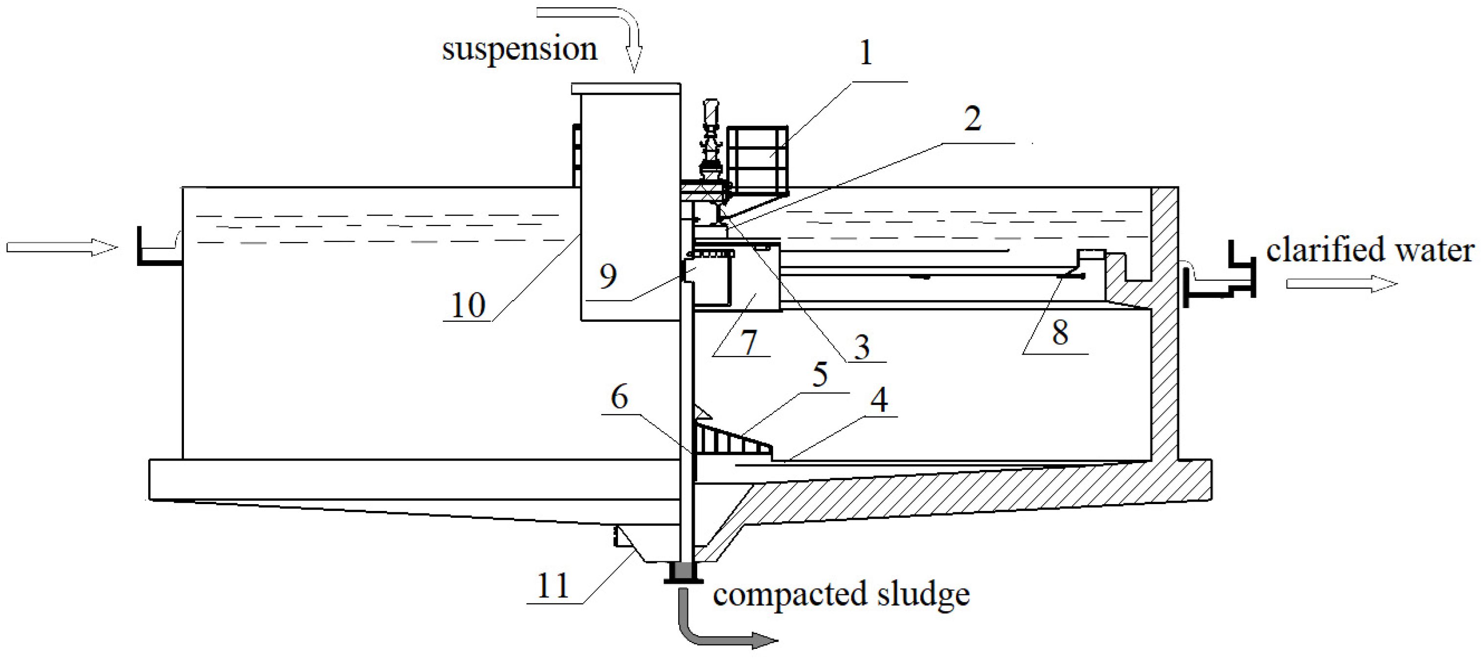
Figure 2 illustrates a drawing of the facility created and its main structure with the components of the designed radial wastewater settling tank.
In the generated radio settling tank, wastewater enters through the openings along a centrally located pipe and is evenly distributed via a distribution device (2), flowing radially towards a peripheral collection channel (5). Devices with various designs can be used to distribute wastewater, although in this specific case, the distribution device has a cylindrical shape with openings (9) through which the wastewater enters and then overflows over the edge, attached to which is a steel strip with V-shaped notches (8). The sludge, deposited on the bottom, is removed with mechanised rakes (5) equipped with scrapers (4) and directed towards the sludge chamber. The radial movement speed is minimal, which creates favourable conditions for the sedimentation of dissolved substances. By employing different devices, the resulting sludge is transferred to a collection chamber (11). The outlet zone of the secondary radial settling tank comprises a peripheral collection channel.
In the design process, the shape of the fastening device is modified, which in secondary radial clarifiers is of essential importance in the design of the facility, as it affects in a specific way the concentration of suspended substances in the thickened sludge and in the recirculated sludge flow. The widely used shapes of the bottom scraper shields are B and C (mainly in the USA, Canada, Germany and Europe), as depicted in
Figure 3 with the corresponding letter designation. They do not provide fast and dense movement of the thickened sludge to the central sludge chamber in which decay of the biomass is observed due to its prolonged stay on the bottom of the clarifier. We modified the shapes described above and designed shape A and shape D. For the specific clarifier, a spiral continuous shape for the scraper shield (shape D) was selected, being sufficiently efficient for not retaining the sludge on the bottom of the facility during its movement to the sludge chamber.
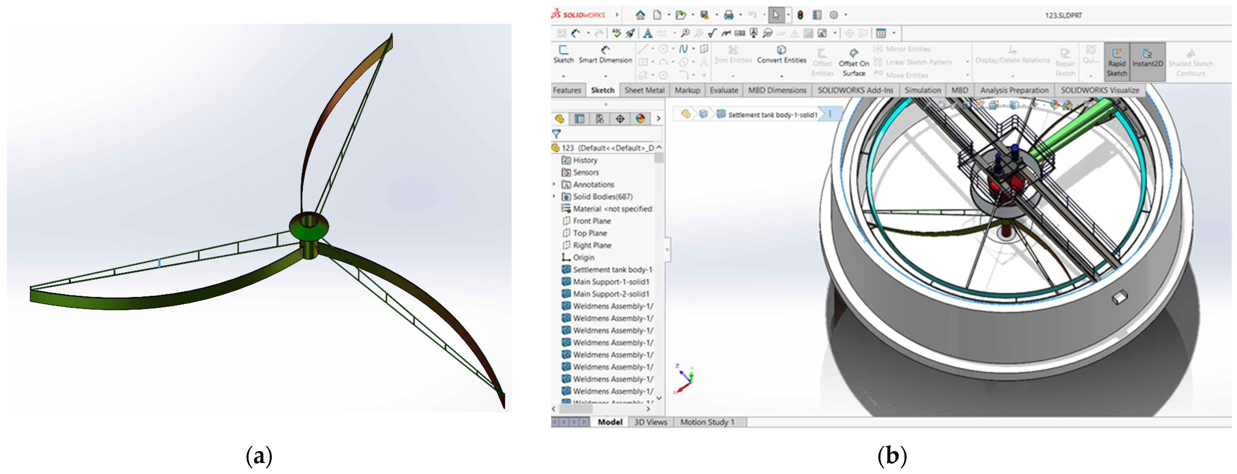
Figure 4a shows the 3D model of the scraper shield, and the scraper device in assembled form is shown in
Figure 4b.
Different solid particles with varying specific gravities display distinct rates of sinking towards the bottom of the radial settling tank. For instance, sand particles exhibit rapid descent as soon as water enters the radial settling tank, while silt or clay particles require multiple rotations around the periphery before settling down. As a result of the vast number of particles swiftly reaching the bottom of the settling tank, the sludge channel is positioned directly in front of the central water pipe.
The current study uses a CFD model to analyse the movement of a two-phase fluid comprising rainwater and sand particles ranging from 1 to 10 mm in size.
The suggested approach, based on examination of the structural features of comparable facilities, is designed to maintain velocities low (0.25–0.5 m/s) to ensure the smooth flow of water and sand mixture at the inlet of the settling tank. Additionally, the rotation frequency of the three-bladed impeller should be kept low (0.3–3 tr/min) for optimal purification efficiency.
The three-dimensional geometric model of the settling tank, created in SolidWorks, is imported into the Design Modeler in ANSYS [
16]. Within this module, all components that are not relevant to the fluid problem under consideration are removed. A thorough check is conducted for the presence of any small openings, edges that do not close surfaces and other imperfections. Finally, a diagnostic analysis of the generated three-dimensional volumes is performed (
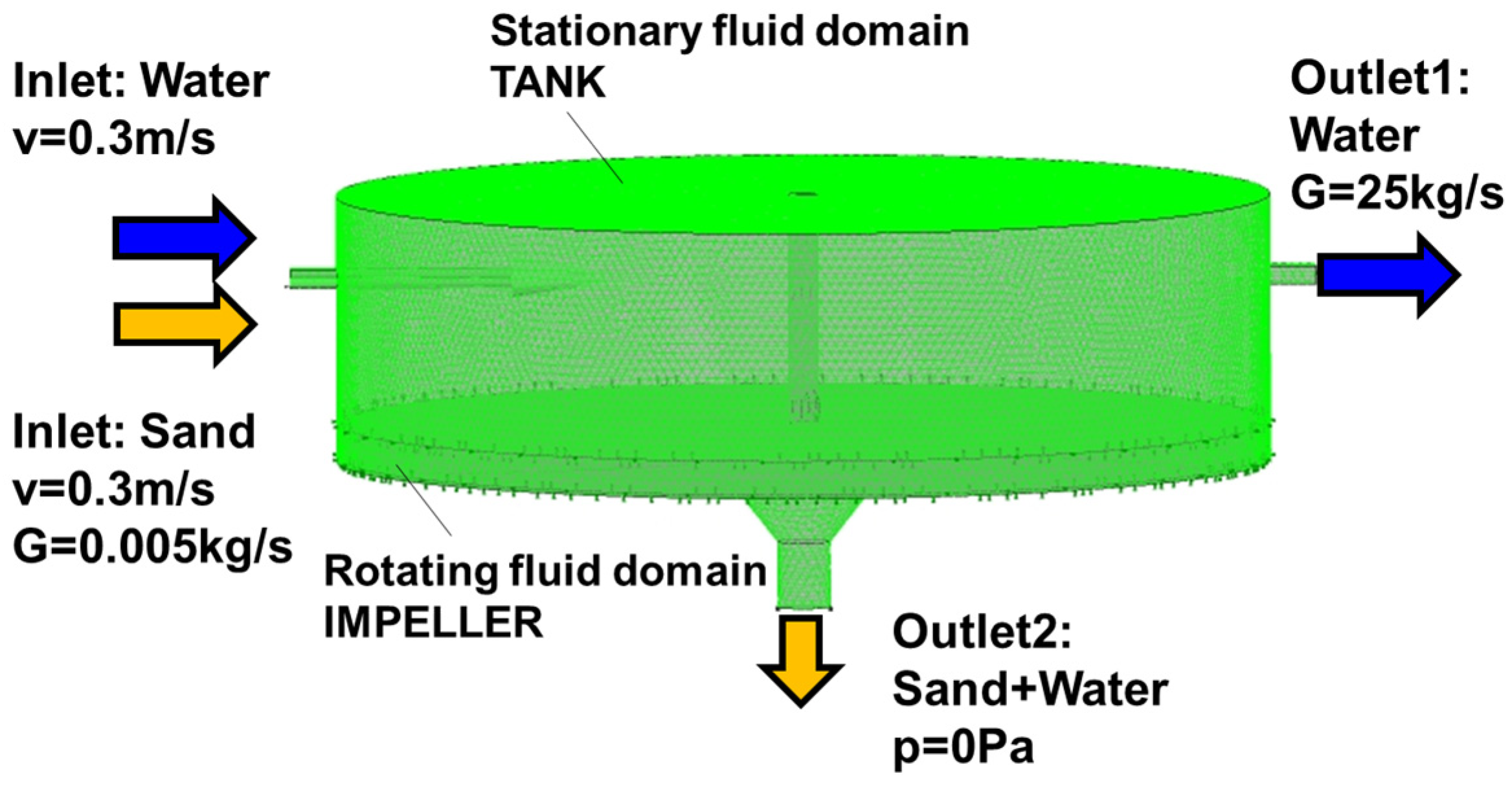
Figure 5a). If no issues are detected, the modelling process proceeds to the next stage. The stationary fluid domain is defined as “TANK”, while the rotating fluid domain named “IMPELLER”—containing the three blades, the drive shaft and the hub—is created separately.
In the Mesh module, a fine mesh is formed with a cell growth gradient of 1.2 near the stationary and rotating walls, and Size Fine settings are applied to the entire module (
Figure 5b). Within the same Mesh module, names are assigned to all surfaces in the three-dimensional fluid domains. There are a total of 462,421 nodes and 2,156,983 elements. In the mesh generation process, 1,962,220 tetrahedra and 2966 pyramidal elements (number of nodes: 462,421; number of elements: 2,156,983; tetrahedra: 1,962,220; pyramids: 2966; wedges: 191,797) are utilised [
17].
The boundary conditions in the CFX-Pre module are set at the inlet of the “TANK” fluid domain (
Figure 5): water and sand particle velocities of 0.3 m/s, particle mass flow capacity of 0.005 kg/s, Outlet 1 flow capacity of 25 kg/s and Outlet 2 average static pressure of 0 Pa. The turbulence model used is k-eps, with calculations performed independently of thermal processes in the fluid domains. Two simulations are available—fully coupled and one-way coupled—both sharing identical settings and physical characteristics of the working fluids. In the first simulation, 250 particles are predefined to assess the impact of the solid phase on the fluid flow. The second simulation involves 4000 particles to determine their volume distribution and to measure the forces acting on the walls of the settling tank and the impeller. Choosing an excessive number of particles is not recommended, as it can lead to overfilling the inlet, which may disrupt the CFX solver’s ability to perform calculations effectively, rendering it impassable at the point of entry. Running the computations concurrently helps identify any discrepancies in the dispersion of the solid phase (sand) within the fluid domains in each of the two simulations. The sand particles have a density of 2300 kg/m
3 and sizes ranging from 1 mm to 10 mm. The particles are evenly introduced through the inlet using the “Uniform Injection“ functionality. To enhance the accuracy of the study, a hydrostatic law distribution representing the vector of gravitational acceleration is incorporated. At Outlet 1 (
Figure 6), a flow capacity of 25 kg/s of outflowing water is specified, while Outlet 2 is set to an average static pressure of 0 Pa. The initial conditions for velocity calculation (0.3 m/s) are also applied. The model includes a rotating area in which Frozen interface settings are applied to the walls of the “IMPELLER” region. The rotation frequency is prescribed at 0.6 tr/min around the vertical axis.
The next step is to configure the computational process in the CFX-Solver module with RMS = 1 × 10
−5, specifically setting the number of iterations to 200. The calculation is performed with the MPI Local Parallel setting to distribute the computational process among four processor cores. Monitoring the convergence of the computational process in the model is crucial to ensure feasible results [
18]. Upon completion of the calculation, a results file is generated containing the data necessary for analysing the movement of the two-phase fluid flow.
3. Results and Discussion
In the next and final stage, the CFX-Post module is applied. The trajectories of the sand particles in both stationary and rotating domains are initially visualised. RES particle track visualisation is ascribed to fully coupled and one-way coupled simulations. It is observed that the trajectories overlap, with minor differences in their spatial arrangement. When visualising the streamlines, it is important to consider the effects of centrifugal and Koriolis forces associated with the rotational motion of the fluid domain modelled in the “IMPELLER” simulation.
Figure 7 outlines the calculated trajectories of sand particles of varying sizes, ranging from 1.7 mm to 8.3 mm. When the impeller rotates at a low frequency, the water entrains the entire volume of sand, causing the trajectories to lean to the left with a displacement from the vertical line. All particles are subject to the gravitational force, with the deviation being shaped by the interplay of inertial and viscous forces. The lightest particles, measuring 1.7 mm, are carried farthest to the left due to the combined effects of the impeller’s rotation and the weaker gravitational force acting upon them. Having high-density-mesh cells positioned close to the wall enables the detection of the presence of a boundary layer. As the sand particles enter the rotating domain, they are exposed to the effects of centrifugal force; yet, the minimal rate of rotation prevents them from being pulled to the periphery. The conical-shaped bottom wall of the sludge chamber facilitates the movement of the sand towards the outlet, allowing it to exit the fluid domain (
Figure 7, Outlet 2).
In
Figure 8a, a pressure isosurface displaying maximum values of 125 Pa illustrates the vortex formation in the fluid domain caused by the rotation of the impeller. The letter A denotes a view towards the inlet where water and sand flow through, with arrows pointing to the inlet and the two outlets within the fluid volume.
Figure 8b provides a close-up view of the trajectories of the sand descending towards the impeller. Using visualisation tools in CFX-Post, the trajectories are colour-coded according to the size of the particles, varying from 1 mm to 10 mm.
Figure 8c depicts two planes in the inlet section where calculations are performed to determine the average contour volume fraction of the water–sand mixture. The blue colour represents 100% of the liquid phase of the mixture, namely water, while the red colour signifies 100% of the solid phase (sand), with the remaining contours showing the varying distribution of the water–sand mixture.
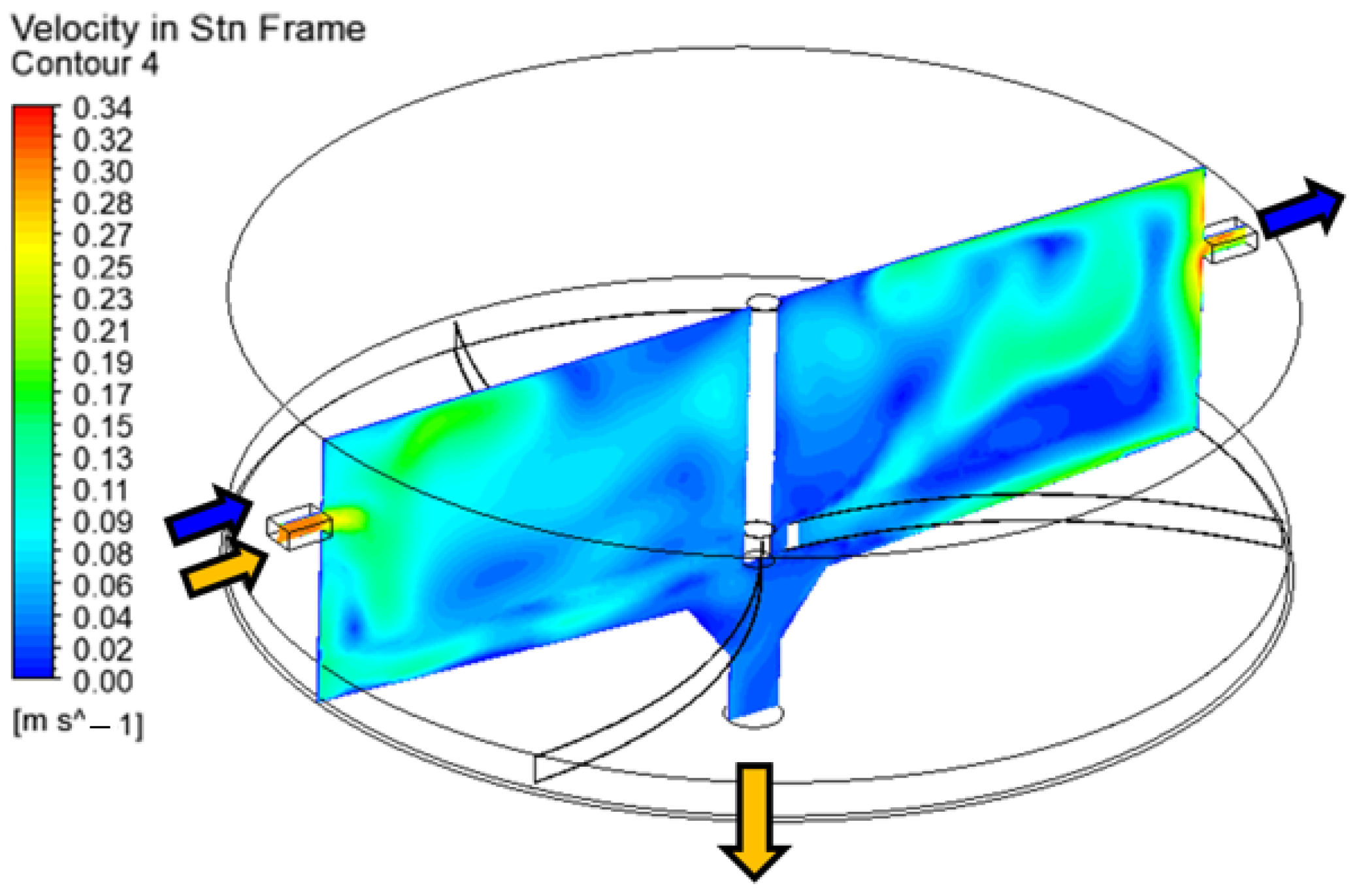
Figure 9 details a defined plane intersecting the axis of rotation, the inlet and Outlet 1, together enclosing both the stationary volume of the “TANK“ and the “IMPELLER“. Within the same plane, calculations of the contours of the absolute velocity of water particles are conducted, revealing a highly swirling flow pattern. The highest velocities of the liquid phase are noted at the inlet, reaching 0.3 m/s. Tracking and analysing the movement of water along the streamlines proves challenging due to the rotating impeller. The modelling predefines the impeller shaft’s wall as rotating (Rotating Wall), with no entrainment of water flow observed around the shaft in the figure. Such an occurrence is attributed to the small radius of rotation, where the centrifugal force is too weak to have a significant impact on the flow dynamics.
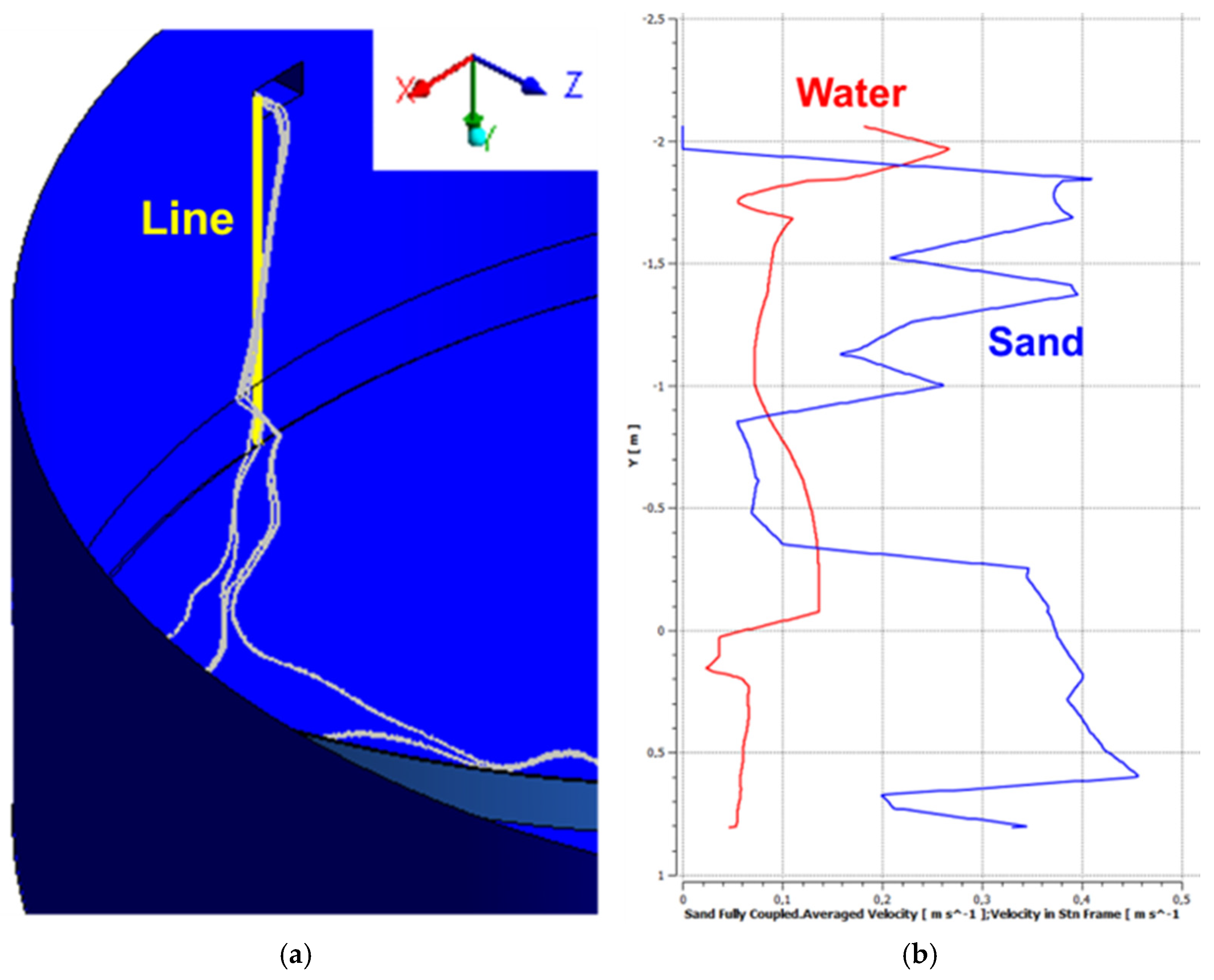
Figure 10a outlines a distinct line originating from the upper left edge of the inlet channel of the settling tank and extending to the gap between the rotating impeller and the wall of the facility. The distributions of the water velocity and the average velocity of the sand particles are calculated using this line.
Figure 10b provides data on the distribution of water velocity with respect to height, reporting a range of 0.05–0.26 m/s. It should be noted that the velocity of the sand particles in the lower half of the settling tank can reach 0.45 m/s, ascribed to the transfer of energy resulting from the rotation of the impeller blades.
4. Conclusions
The design of a working 3D model of a radial clarifier in the SolidWorks environment and the construction of an optimal shape of the scraper mechanism in order to prevent sediment from being retained at the bottom of the facility, as well as its insertion into the ANSYS CFX software for subsequent simulation of its purification function, were successfully completed, with the following results.
The initial CFD analysis discussed throughout this paper revealed several key findings:
Particles with sizes 4–7 mm traverse the path from the inlet to the outlet of the settling tank in 172 s;
Sand particles with sizes of 9–10 mm register the maximum calculated velocity of 1.3 m/s, predominantly perceived at the periphery of the rotating impeller blade;
The highest absolute velocity of water reaches 0.48 m/s at the periphery of the rotating fluid domain;
The total pressure (total pressure Sth frame) manifests its lowest values in the upper corners of the settling tank, measuring 227 Pa.
The results obtained offer valuable insights into the movement of the solid phase and water within the fluid domain, demonstrating the effect of the rotating elements when specific boundary conditions are applied at the fluid domain inlet. The optimal conditions for the sedimentation of dissolved substances are provided by the relatively low velocity of wastewater movement in the radial direction, as highlighted in the analysis.
Optimisation procedures, such as changing the flow parameters, impeller speed and geometric shape of the main components, can be applied to the model created for broader engineering implications and potential design recommendations for practitioners. The optimisation process will in turn reveal whether there is an opportunity to enhance the facility’s performance and reduce the particles’ residence time in the settling tank, which will be a future challenge for those involved in the current project.
