1. Introduction
In modern industrial and manufacturing systems, the reliability and efficiency of machines and equipment are critical for maintaining process continuity and minimizing operational costs. One of the most important aspects of preventive diagnostics and maintenance is the monitoring of mechanical vibrations, which serve as key indicators of the health and operability of equipment. Measuring vibrations through accelerometric sensors is a vital tool, as it enables the early detection of anomalies related to wear, imbalance, performance changes, or other defects associated with technological equipment.
Accelerometric sensors convert mechanical oscillations into electrical signals that can be quantitatively analyzed. This enables precise determination of the frequency, amplitude, and waveform of the vibrations, which are directly related to the condition of machines [
1]. For example, changes in the vibration spectrum can indicate bearing failures [
2], as well as gear or motor rotor issues [
3], long before critical damage occurs. In sectors such as energy, automotive and transportation [
4,
5], aviation, and heavy industry [
6], this has direct impacts on safety, economic losses, and environmental footprint.
Furthermore, the use of accelerometric systems is especially valuable in the contexts of the Industrial Internet of Things (IIoT) and Industry 4.0 [
7,
8], as well as the ongoing digital transformations in industry, where sensor data is integrated into machine learning and predictive analytics systems. This allows not only for automated monitoring, but also for optimization of maintenance schedules, thereby reducing downtime and equipment repair costs.
The aim of this paper is to present the development of a low-cost system for collecting data from accelerometric sensors, built using affordable components, which allows data to be measured and recorded in files.
2. Block Diagram of the Device and Used Components
The device for collecting data from accelerometric sensors has the following block diagram—see
Figure 1.
The main components include a 32-bit microcontroller ESP32 manufactured by Espressif Systems (Shanghai, China). It has sufficient memory, an SD card for data storage, a real-time clock to determine the start time of the measurements, and a power supply, necessary for the operation of the device. An external accelerometric sensor is connected to the device, which is mounted on the object where the vibrations would be measured and analyzed.
3. Schematic Diagram and Printed Circuit Board
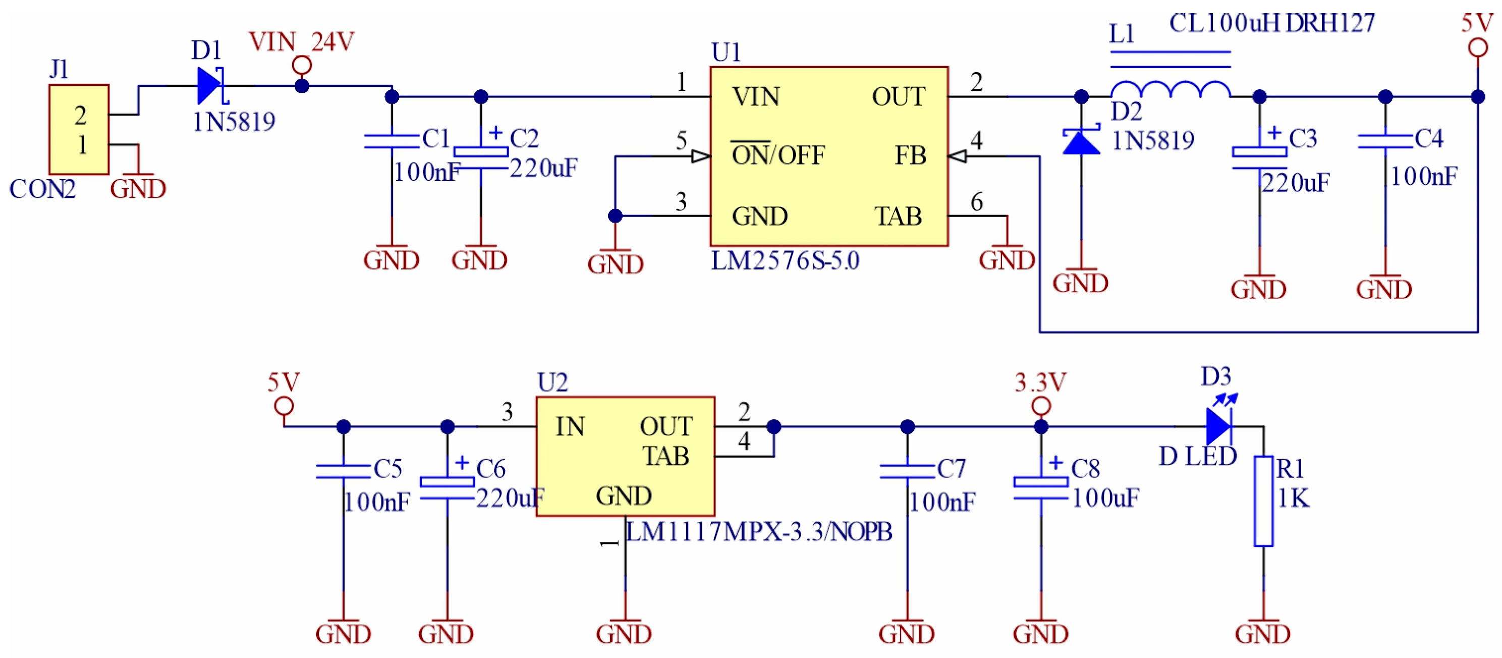
The power supply of the developed system includes a switching regulator, LM2576 (Texas Instruments, Dallas, TX, USA), which provides a 5 V supply voltage to the board. In addition, a second regulator (LM1117, Texas Instruments, Dallas, TX, USA) supplies 3.3 V to the individual components that are connected to and communicate with the ESP32 microcontroller.
Figure 2 shows the power supply schematic.
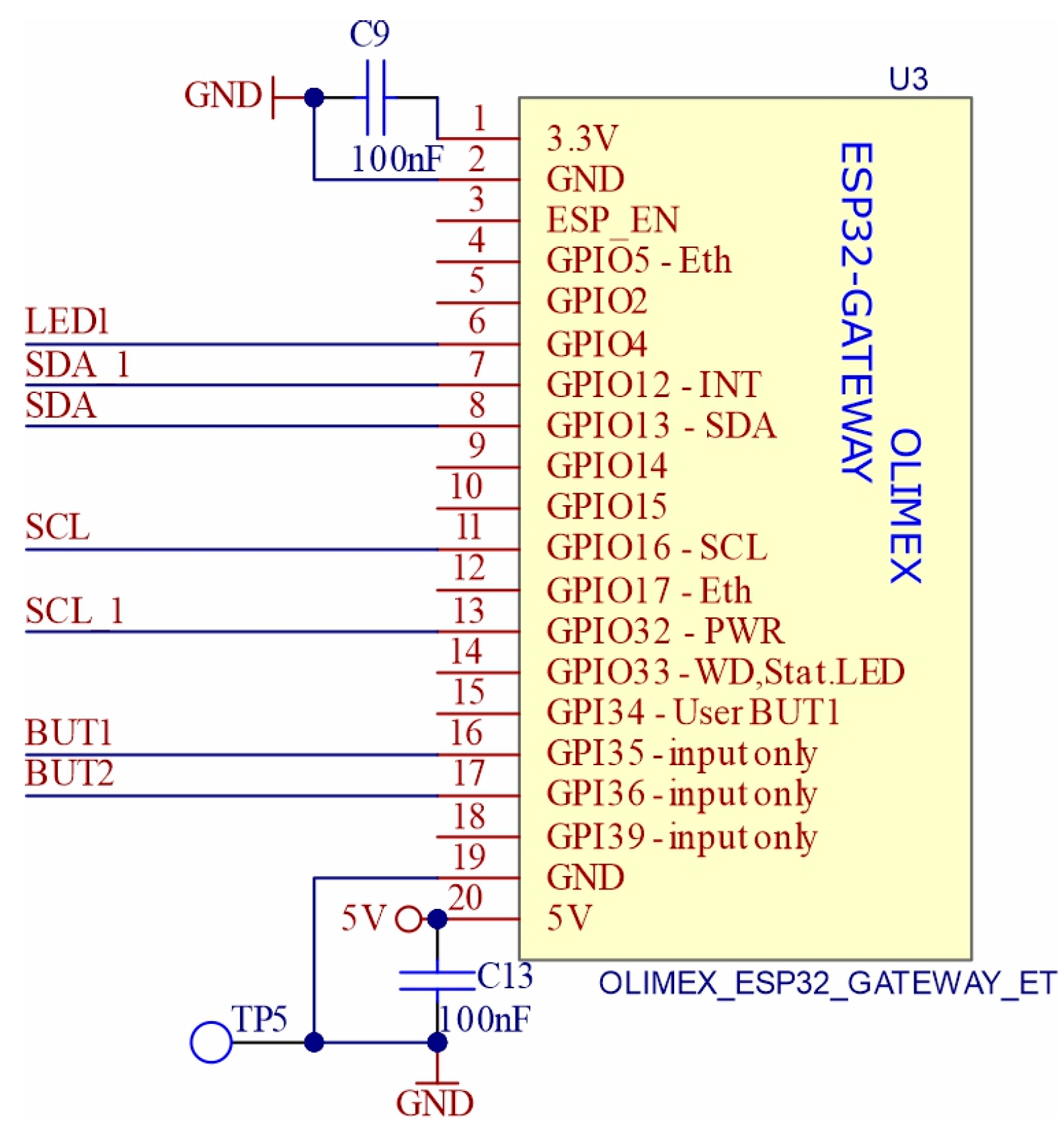
The core of the developed system is based on the ESP32-GATEWAY(Olimex, Plovdiv, Bulgaria), a development board by Olimex designed for IoT applications. This board utilizes the ESP32-WROOM microcontroller module by Espressif, which provides Wi-Fi and Bluetooth Low Energy (BLE) communication in the 2.4 GHz frequency range. Furthermore, the ESP32-GATEWAY supports wired Ethernet (100 Mbps), as well as USB communication, in addition to SPI and I2C interfaces.
Figure 3 illustrates the ESP32-GATEWAY connection setup.
Since the ESP32 supports two I2C interface ports, the first port was connected to two connectors intended for use with vibration accelerometric sensors. The second I2C port was designated for connecting additional sensor modules. A specialized chip, the TCA9548, was connected to this port. It is an I2C multiplexer that allows up to eight external I2C devices to be connected.
Figure 4 shows the connection of the multiplexer module.
Connected to the multiplexer chip was a real-time clock (RTC) of type MCP79410 produced by Microchip (Chandler, AZ, USA), which was used to determine the exact time when measurements started. Additionally, its data was used to generate uniquely named files.
Figure 5 shows the RTC connection.
A temperature sensor was also installed on the board (see
Figure 6) and used to determine the environmental conditions under which the measurements were taken using the developed system.
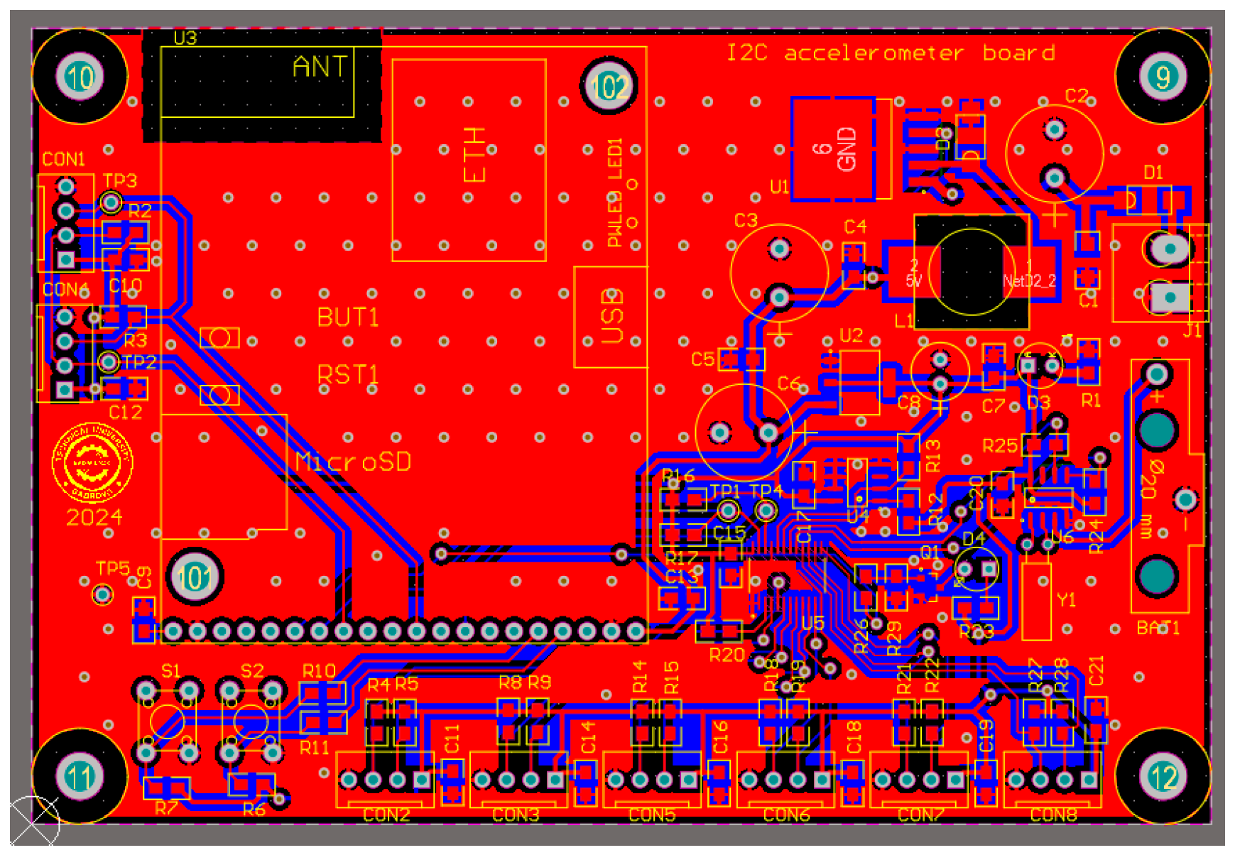
The device’s printed circuit board was designed to be two-layered, and special attention was given to minimizing the influence of electromagnetic interference on signal traces during its design.
Figure 7 presents a view of the developed PCB.
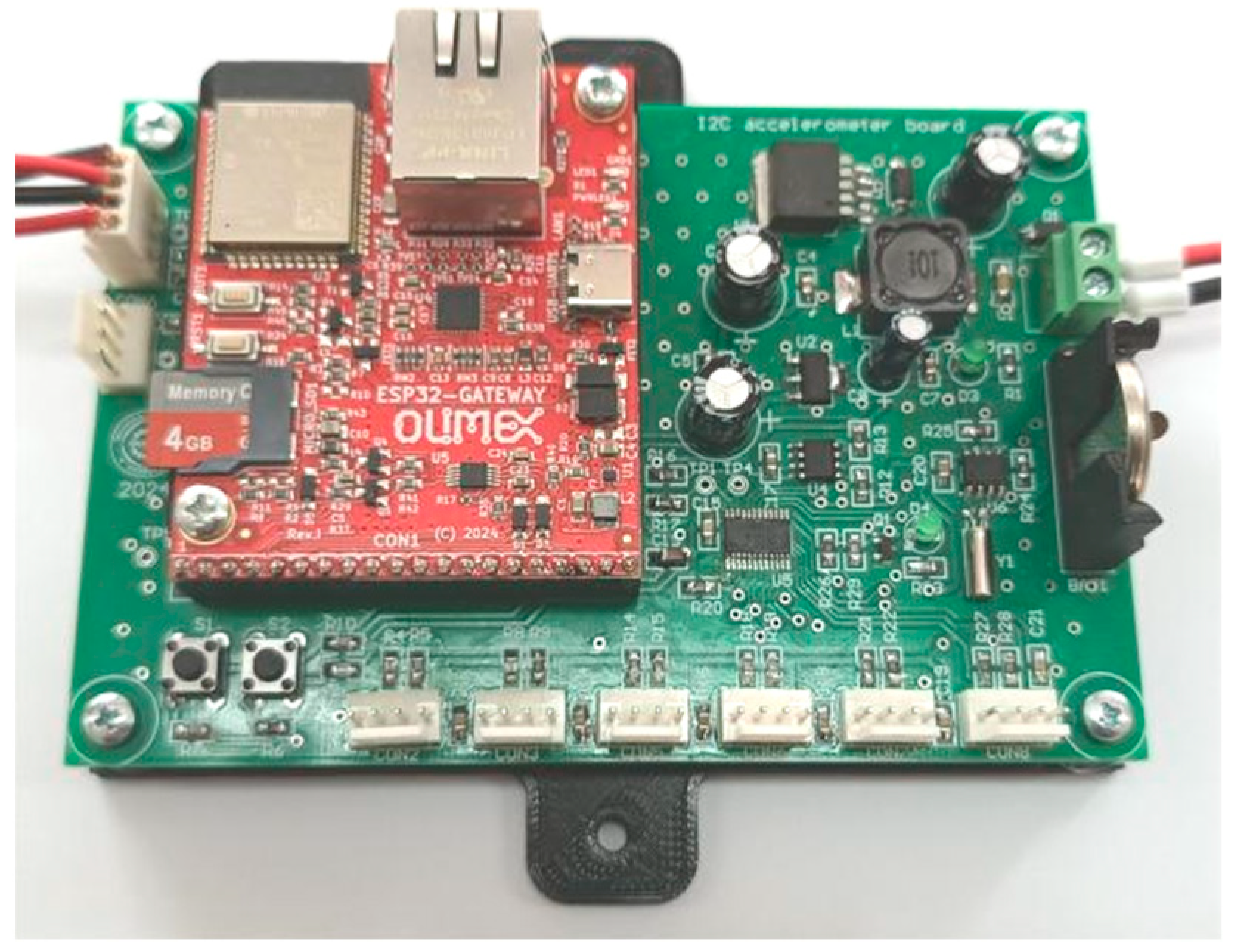
The device was fully assembled (
Figure 8), with all chips and connectors mounted. The development kit ESP32-GATEWAY was also mounted to the board using a specially designed attachment.
4. Basic Operating Algorithm
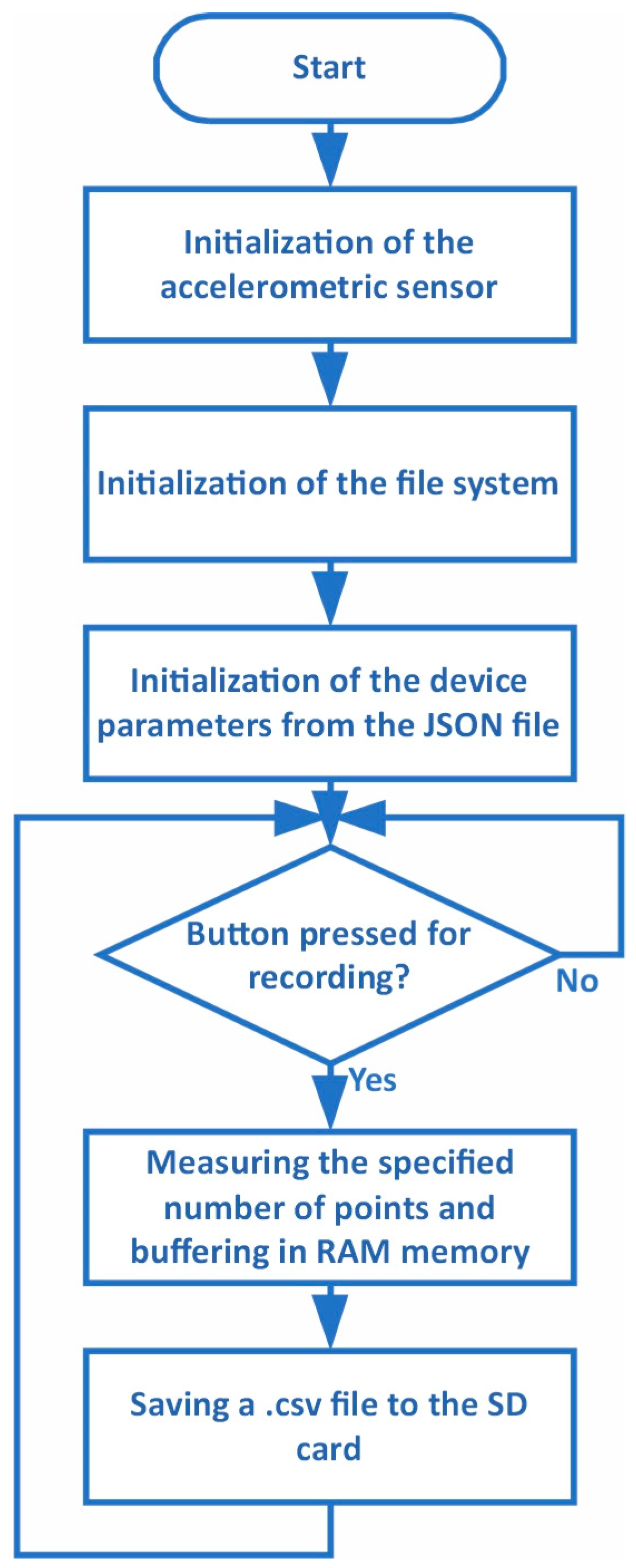
The system’s operating algorithm (
Figure 9) includes a sequence of steps in which the accelerometer is initialized, a file system is created on the SD card, and the system parameters are loaded. After this, the system enters a standby mode. Upon the press of a button by the user, the data measurement begins. The number of points to be measured and the time delay between two consecutive measurements are stored as parameters in a JSON configuration file. Based on this data, the system dynamically allocates a buffer in RAM memory, where the measurements are sequentially recorded. Once all the designated points are collected and the buffer is filled, data is saved to a .csv file on the SD card. This file has a unique name that includes the date and time of the measurements.
5. Device Functionality Testing
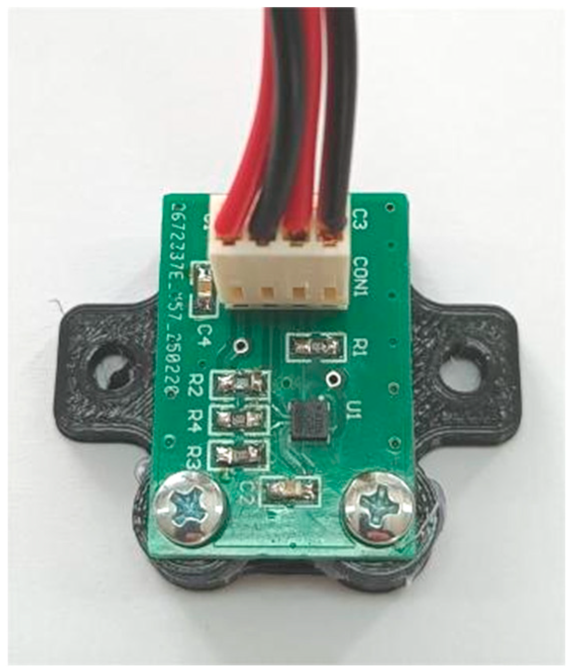
To test the functionality of the developed device, an accelerometer module was created, based on the LIS3DHTR accelerometer produced by STMicroelectronics (Geneva, Switzerland). The LIS3DHTR is a three-axis MEMS accelerometer with digital output, developed by STMicroelectronics. It is intended for applications requiring low power consumption and high performance. Its measurement ranges are ±2 g, ±4 g, ±8 g, or ±16 g, with a sensitivity of 64 mg. The accelerometer supports I2C and SPI digital interfaces; in our case, the I2C interface was used. LIS3DHTR is suitable for a wide range of applications, such as free-fall detection, single-/double-tap recognition, vibration monitoring and detection, etc.
Figure 10 shows the developed accelerometer module.
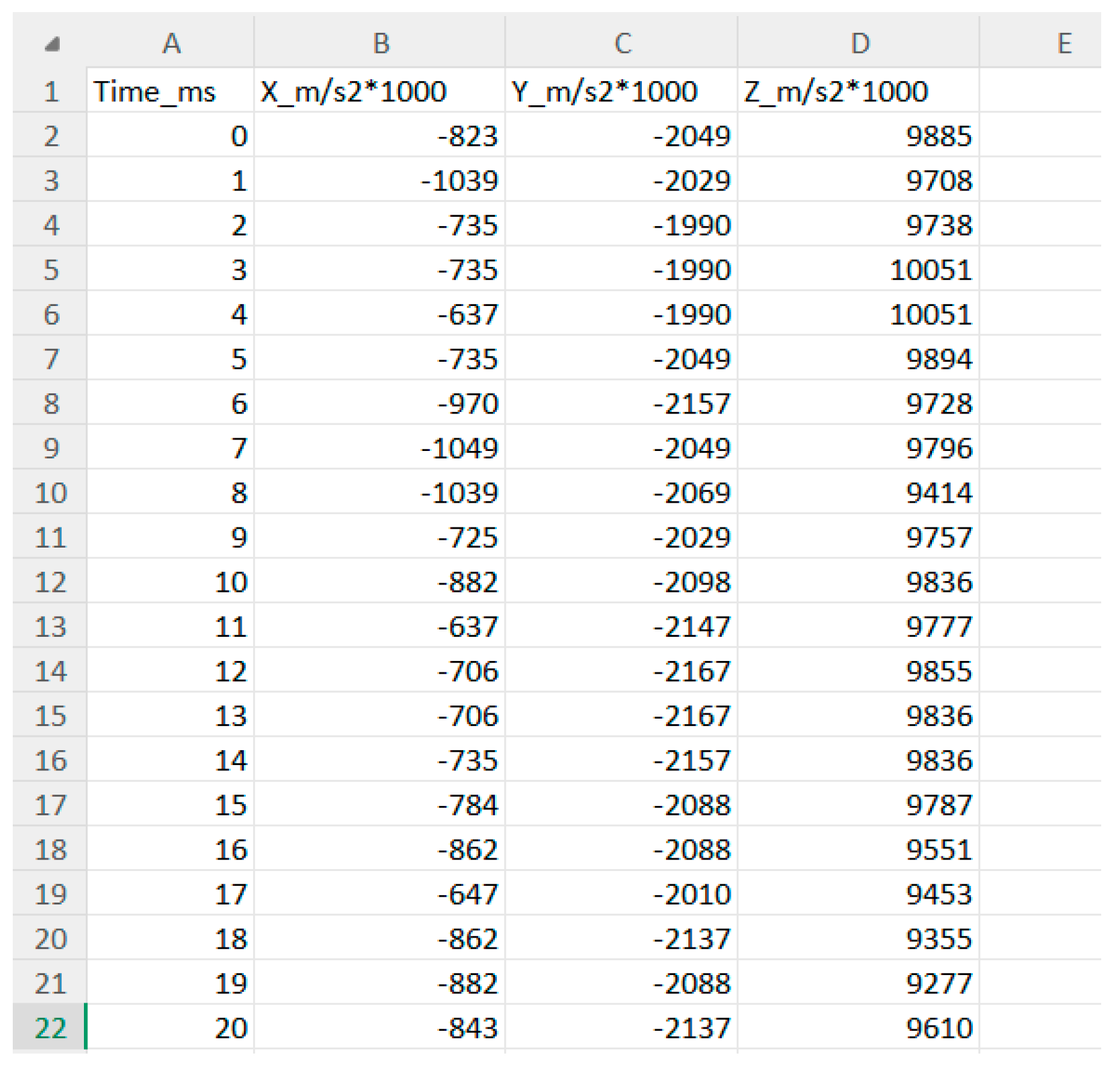
Using the developed accelerometer module, data collection was performed. During the data collection process, the board’s configuration and operating modes were set through parameters specified in the JSON configuration file located on the SD card. The collected vibration data was stored in a separate .csv file for each measurement.
Figure 11 shows the structure of such a file.
The collected data can easily be imported into specialized environments for processing, such as Matlab 2022a. Since the data from the accelerometer also contains noise, using a mathematical processing environment allows for noise filtering.
Figure 12 shows changes in the accelerometer’s
X-axis data with a moving average filter applied.
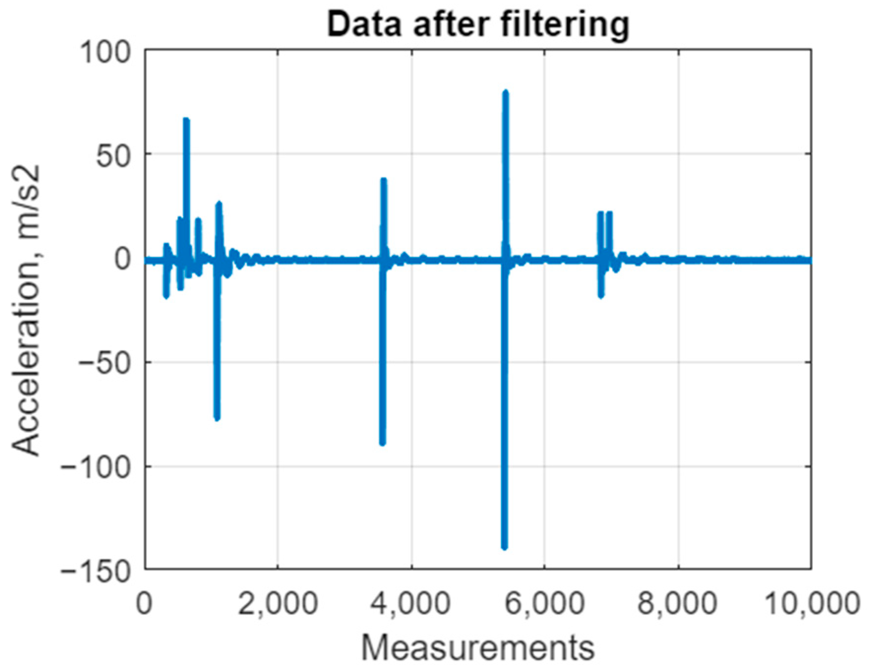
Using such mathematical environments, it is quick and easy to extract only the values or data segments of interest—those that carry important information from the measurement—as shown in
Figure 13.
Based on the filtered data, more complex structures can be created—such as spectrograms—which visualize the signal’s frequency characteristics over time, as shown in
Figure 14.
Spectrograms, in turn, can be used to train an artificial neural network to recognize specific characteristics in the signal. In this case, spectrograms can be treated as two-dimensional images that are fed into a standard convolutional neural network (CNN) for classification.
6. Conclusions
This study presents the design and implementation of a cost-effective data acquisition system for vibration monitoring, utilizing accelerometric sensors and a 32-bit ESP32 microcontroller. The proposed system offers a low-cost alternative to conventional vibration data acquisition solutions, which are essential for assessing the operational conditions of machinery and equipment.
The developed device can be deployed in various industrial and research applications, including predictive maintenance of rotating machinery like motors, pumps, and bearings, to detect early signs of wear or misalignment, and also for vibration analysis in engines, gearboxes, and other critical components of machines.
The acquired vibration data can be further processed using computational tools and used to train artificial neural networks. This enables the detection and classification of machine faults based on deviations in vibration patterns and also enhances predicative maintenance capabilities.

