Article

Numerical Investigation of Fluid–Structure Interaction of Foreign Objects in Steam Generator Tube Bundles

1
Suzhou Nuclear Power Research Institute, Suzhou 215000, China
2
Zhejiang Institute of Tianjin University, Ningbo 315200, China
3
School of Chemical Engineering and Technology, Tianjin University, Tianjin 300072, China
4
Yangjiang Nuclear Power Co., Ltd., Yangjiang 529941, China
5
State Key Laboratory of Chemical Engineering and Low-Carbon Technology, Tianjin 300072, China
*
Author to whom correspondence should be addressed.
J. Nucl. Eng. 2025, 6(4), 47; https://doi.org/10.3390/jne6040047
Submission received: 8 September 2025 / Revised: 14 November 2025 / Accepted: 17 November 2025 / Published: 19 November 2025
(This article belongs to the Special Issue Advances in Thermal Hydraulics of Nuclear Power Plants)

Abstract

As a critical component of nuclear and thermal energy conversion systems, the long-term safe operation of a steam generator depends on the structural integrity of its tube bundles. Foreign objects introduced into the secondary side can induce flow-induced vibrations and wear, potentially causing tube wall damage and unplanned outages, thereby affecting overall system reliability. This study systematically investigates the flow-induced vibration behavior of foreign objects within steam generator tube bundles and explores the influence of object geometry through three-dimensional fluid–structure interaction (FSI) simulations. The foreign objects are modeled as single-degree-of-freedom rigid bodies, and their dynamic responses are captured using a coupled flow–motion framework. Results reveal that object geometry significantly influences flow separation, variations in lift and drag forces, and displacement characteristics. Cylindrical and irregular objects exhibit stable, low-amplitude vibrations; plate-shaped objects experience restricted motion due to large drag areas and symmetric contact constraints; whereas helical objects show the largest displacements arising from coupled axial–radial vibrations and complex vortical structures. These findings demonstrate that the interplay between aerodynamic forces and geometric complexity strongly governs the flow-induced vibration of foreign objects, offering insights into their motion behavior and potential impact on steam generator tube bundle integrity.

1. Introduction

The steam generator, as a key component in nuclear and thermal energy conversion systems, plays a crucial role in ensuring the overall safety and reliability of the plant [1,2]. However, foreign objects on the secondary side can interact with the tube walls through impact, sliding and flow-induced vibration, causing fretting and contact wear that may progressively thin the tube wall and ultimately produce through-wall penetration, coolant leakage and unplanned outages [3,4]. Among the various failure mechanisms, fretting wear induced by foreign objects has a particularly significant impact on the long-term structural integrity of steam generators. Fretting wear refers to gradual material loss occurring at contact interfaces due to small-amplitude relative motion. When foreign objects exist on the secondary side of the steam generator, they interact with the inner walls of the heat transfer tubes under fluid-induced forces, leading to fretting wear and potential tube degradation [5,6,7,8,9].
To address the issue of fretting wear caused by foreign objects on the secondary side of steam generators, extensive research has been conducted both domestically and internationally [10,11]. Mahey S et al. [12] revealed through experiments that minor geometric changes in foreign objects could significantly alter their root-mean-square amplitude. These objects primarily exhibit planar response characteristics within tube bundles, with the amplitude response in the Z direction being particularly prominent. Their interactions mainly manifest in the form of sliding. This finding is significant for understanding the dynamic behavior of foreign objects in tube bundles and their impact on steam generator performance. Kima H. N. et al. [13] used a zonal approach and single-span modal analysis to predict tube wall wear, ensuring the integrity of tube walls and the safe operation of nuclear power plants without removing foreign objects. Njuki Mureithi et al. [14] investigated the characteristics of turbulence forces acting on foreign objects within steam generator tube bundles, revealing a close correlation between the turbulence forces on foreign objects and those on the tube bundles, and proposed a drag coefficient prediction method based on turbulence force correlation.
However, due to the highly random nature of fluid-induced vibrations (FIV) caused by the movement of foreign objects within tube bundles, fully predictive studies of fretting wear remain challenging, and the application of three-dimensional fluid–structure interaction (FSI) simulations in this context is relatively limited [15,16,17]. The U.S. EPRI has conducted extensive simulations of foreign object motion within tube bundles, employing a combined CFD and Simulink approach to calculate object displacements [18]. However, this method neglects the feedback effects of object motion on the surrounding flow field. Instead of directly calculating wear, this work focuses on the influence of object geometry on FIV, enabling indirect inference of potential wear trends. Accordingly, three-dimensional FSI numerical simulations are employed to capture the motion of foreign objects on the secondary side of steam generators, and the simulation methodology is validated against existing experimental data. The results of this study help to investigate the characteristics of flow-induced vibrations of foreign objects and provide a reference for the potential damage caused by such vibrations in steam generator tube bundles.

2. Development of the Fluid–Structure Interaction (FSI) Model for Foreign Objects

Flow-induced vibration (FIV) of foreign objects involves the coupled interaction between the fluid and solid domains, which substantially increases the computational complexity and cost of numerical simulations. Therefore, based on computational fluid dynamics (CFD) methods, a simplified FSI model was developed in this study by combining a rigid-body structural assumption, dynamic mesh technology, and the user-defined expression functionality in ANSYS CFX 2020 R2, Canonsburg, PN, USA.

2.1. Simplification of the Foreign Object Structure

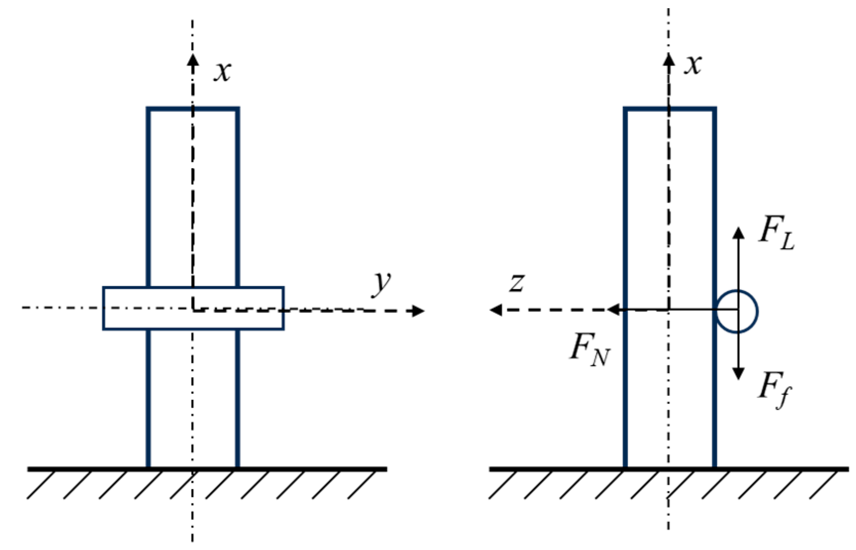
Since foreign objects inside the tube bundle are in an unconstrained state with complex motion patterns, a representative single-degree-of-freedom (1-DOF) motion was selected for modeling. Specifically, the foreign object is subjected to flow-induced forces and moves along the axial direction between two adjacent heat transfer tubes, as illustrated in Figure 1. The motion in the x-direction is defined as the primary vibration direction, while displacements in the y- and z-directions, as well as rotations about all three axes, are constrained. Only the translational motion along the x-axis is retained. This modeling approach is consistent with the typical configuration adopted in related EPRI studies [18].
In the 1-DOF configuration, the vibration direction of the heat transfer tubes is orthogonal to the motion of the foreign object. Dynamic mesh simulations under such conditions may lead to mesh distortion or collision. Considering that the tube vibration exerts minimal influence on the flow-induced forces acting on the foreign object, the tube bundle is treated as a stationary boundary condition representing the flow environment. Thus, the vibration of the heat transfer tubes is neglected during the simulation of the foreign object’s flow-induced vibration.

2.2. Dynamic Model of the Foreign Object

A dynamic interaction model between the foreign object and the adjacent heat transfer tubes was established, as illustrated in Figure 2. In this study, gravitational and buoyant forces were neglected because the simulation focused on the unsteady fluid-induced forces that dominate the motion of foreign objects within the tube bundle. This simplification is consistent with the approach adopted in Ref. [19], where the mean component of external loads was removed before dynamic simulation. Consequently, the object oscillates around an equilibrium position without a net unbalanced force, allowing the transient motion to be driven solely by the fluctuating hydrodynamic loads. Under such assumptions, gravity would merely shift the equilibrium position and has little effect on the vibration characteristics.
Accordingly, the foreign object is modeled as a rigid body with one translational degree of freedom along the x-axis. The forces acting on the foreign object during the two-way fluid–structure interaction simulation are shown in Figure 2. In the figure, FL and FN represent the drag force and lift force acting on the foreign object, respectively; Ff represents the contact friction force between the object and the tube surface.
During the simulation of wear between foreign objects and heat transfer tubes, the magnitude and direction of frictional forces often change with contact conditions. Therefore, incorporating a dynamic friction force based on the Coulomb friction model provides a more accurate representation of the wear behavior between foreign objects and heat transfer tubes [20,21,22]. This model’s significance lies in its ability to dynamically adjust the frictional force’s magnitude and direction according to variations in resistance.
F f = μ F N s g n ( v )
s g n v = 1 , v > 0 0 , v = 0 1 , v < 0
where
sgn(v)—sign function indicating the direction of the frictional force;
μ—coefficient of friction;
v—relative velocity of the foreign object;
FN—normal hydrodynamic force acting on the contact surface.

3. Numerical Model and Methodology

3.1. Establishment of the Foreign Object Model

The shape of foreign objects in steam generators has a direct and significant influence on their flow-induced vibration characteristics [12]. Therefore, geometry was chosen as the primary factor to investigate the interaction between foreign objects and the heat transfer tubes. All selected geometries were organized into a parametric matrix to systematically study the flow-induced vibration behavior of foreign objects on the secondary side of the steam generator.
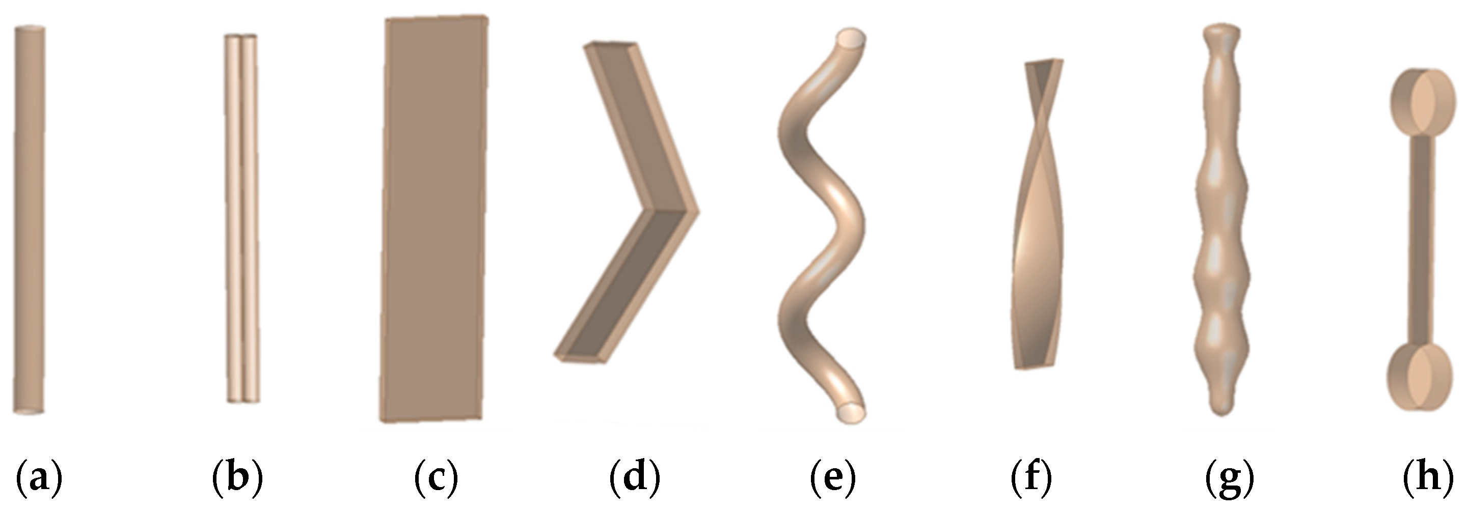
Common foreign objects (FOs) found in steam generators—such as metal wedges, flat plates, check valve pins, threaded rods, and welding electrodes—typically possess well-defined geometries and are generally classified as cylindrical or plate-like objects. In contrast, FOs with irregular or complex shapes, including debris such as gravel, rust flakes, sponge particles, steel brush filaments, wood chips, and fragmented metal pieces, are categorized as helical or irregular types. These geometries constitute the majority of FOs detected on the secondary side of steam generators [23].
The representative foreign objects selected in this study were chosen based on their practical relevance and occurrence frequency in operating nuclear power plants. Specifically: Cylindrical objects simulate typical rod-like components (e.g., welding electrodes and bolts) that may accidentally fall into the secondary side during maintenance; Plate-like objects represent flat debris or spring fragments, which are frequently observed during field inspections and post-service examinations; Helical objects correspond to twisted or coiled fragments, such as springs or curled metal pieces; Irregular objects include other fragments with complex shapes.
The chosen geometric models cover the most common foreign object morphologies encountered in practice. For comparison purposes, all models were assigned the same mass. Detailed schematic representations of these classifications are shown in Figure 3.

3.2. Development of the Numerical Model

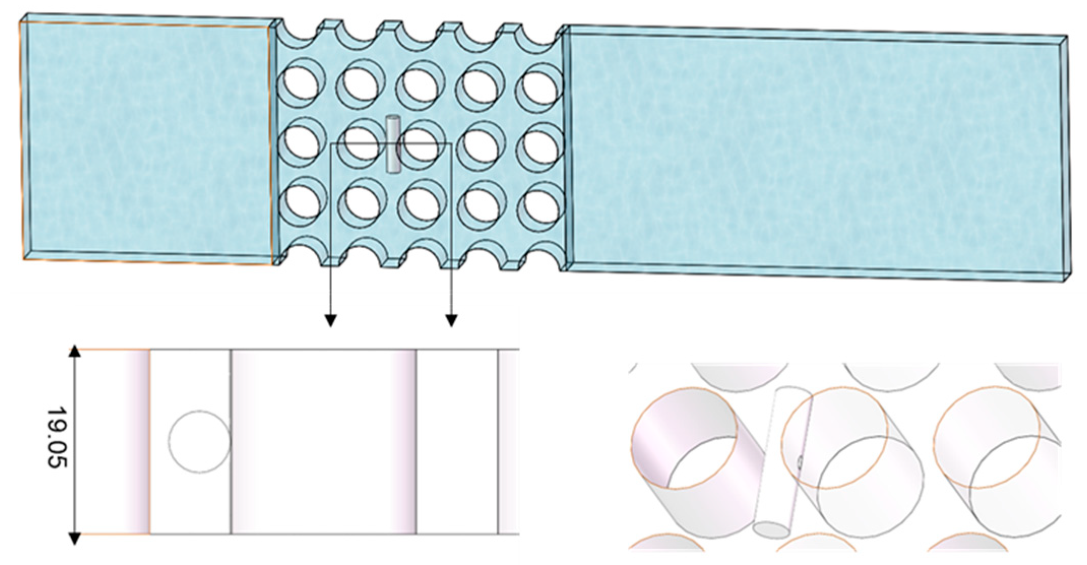
Foreign objects in tube bundles are in contact with heat transfer tubes. During simulation, this contact state can result in mesh distortions and negative volume errors caused by mesh intersections between the heat transfer tubes and foreign objects. To address this issue, the foreign object was modeled with a small separation from the heat transfer tube, creating a finite gap to prevent computational errors caused by mesh interference. A comparative analysis of lift forces and drag forces for different gap sizes (0.05–0.5 mm) showed that when the gap is within 0.1 mm, its influence on the flow field around the foreign object can be considered negligible. Based on the findings of Wu Hao [24] in his study of fluid-elastic instability in square tube bundle arrangements, the axial dimension of the model must be at least equal to the tube diameter. To reduce computational complexity, the axial dimension of the straight tube segment in the model is set to 19.05 mm, as shown in Figure 4.
The specific parameters of the three-dimensional model are shown in Table 1. and the detailed parameters for foreign objects are summarized in Table 2.

3.3. Grid Parameter Settings

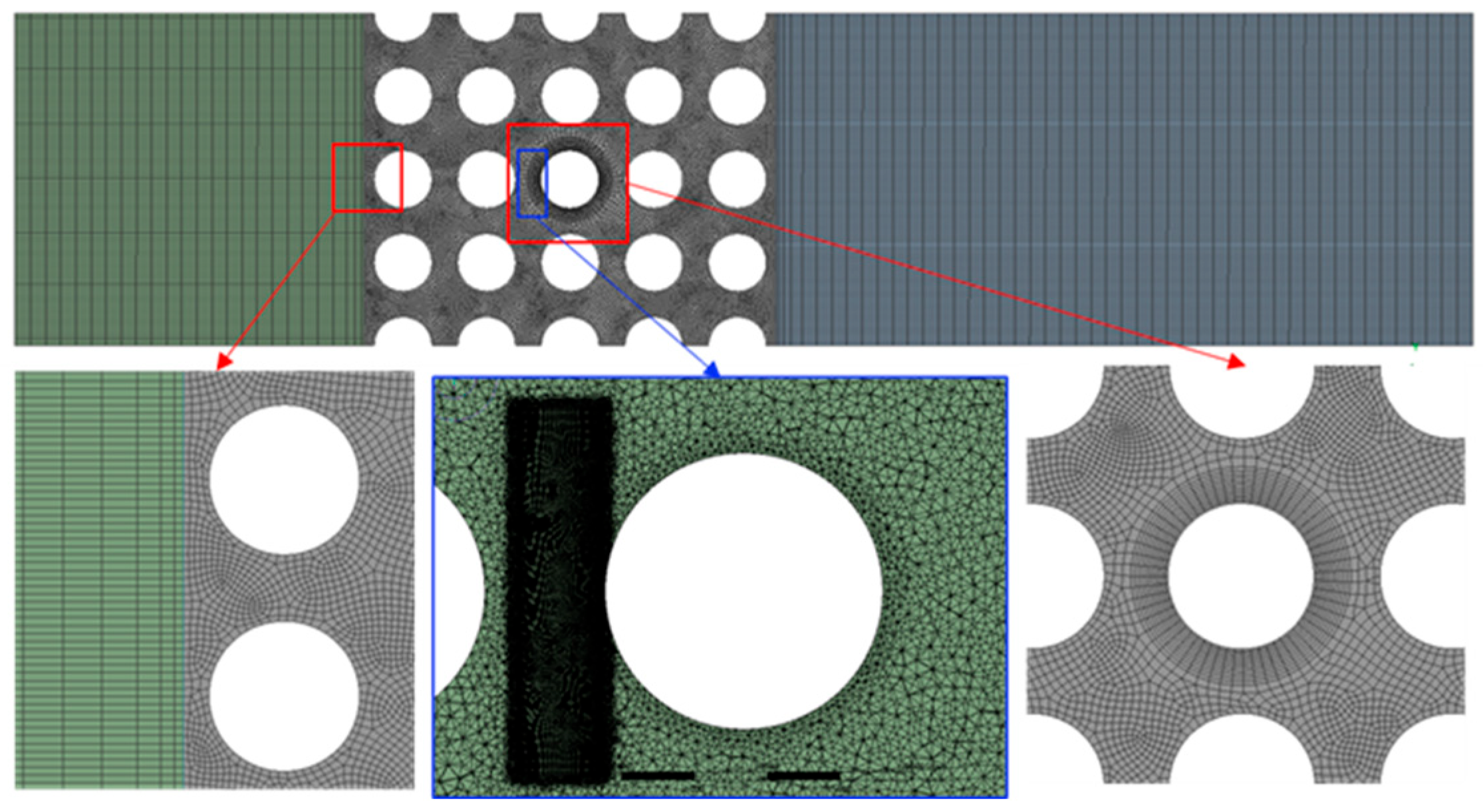
To ensure computational stability and accuracy when foreign object displacement is significant, the flow field around the foreign object is divided into regions and mesh refinement is applied. In this model, the boundary of the foreign object is set as a dynamic mesh, while all other boundaries are treated as walls. A hybrid mesh division approach is employed using zoning operations, with refined mesh applied to the foreign object boundary. The meshing process utilizes the cutting function in SolidWorks 2019 (Waltham, MA, USA) in combination with the ANSYS Meshing module. The overall schematic of the mesh division is shown in Figure 5.
The inlet and outlet regions feature regular geometries and low turbulence intensity; therefore, hexahedral grids with a mesh size of 2 mm were applied to reduce the total number of elements and improve numerical efficiency. In contrast, the tube bundle region, where the flow field becomes highly complex due to the presence of foreign objects, was discretized with tetrahedral elements to better capture curved surfaces and local flow separation. Specifically, the mesh around the foreign object and the adjacent heat transfer tubes was refined with five near-wall grid sizes: 0.05 mm, 0.1 mm, 0.3 mm, 0.5 mm, and 1.0 mm. The remaining tube bundle region used a mesh size of 1 mm. Table 3 presents the mean values of drag force in the transverse flow direction for a cylindrical foreign object of 6 mm diameter under different mesh resolutions. After grid independence verification, the optimal mesh size around the foreign object and surrounding tubes was determined to be 0.1 mm, with the total number of elements in the entire model reaching 6,893,215.

3.4. Simulation Boundary Condition

Table 4 summarizes the simulation setup and boundary conditions. The front and rear planes were defined as symmetry planes, and the heat transfer tubes were modeled as rigid walls. To model turbulence, the standard k–ε model was primarily adopted. This model has been widely validated for cross-flow around cylinders and tube bundles, particularly under moderate Reynolds numbers (103–105), where it provides stable and computationally efficient results. Rodriguez et al. [25] compared several RANS models and confirmed that the standard k–ε formulation offers reliable predictions of mean flow and transverse force characteristics in incompressible cross-flow simulations [26].
In this study, due to the presence of slits and unsteady vortex shedding, a comparative simulation of the k–ω SST turbulence model was performed on a 6 mm cylindrical foreign object. The results show that the differences in the average lift cand drag forces predicted by the two turbulence models are both less than 3%. Therefore, for the sake of numerical stability and computational efficiency, all subsequent simulations adopted the standard k–ε model.
As shown in Figure 6, an independent coordinate system was established for the foreign object, which was modeled as a rigid body. Monitoring points for lift forces coefficient, drag coefficient, and displacement were assigned to the foreign object. The heat transfer tubes were modeled as rigid and thus excluded from monitoring.
The inlet boundary condition is specified as a velocity inlet, while the outlet boundary condition is set as a pressure outlet with a relative pressure of 0 Pa. The tube bundle wall surfaces are modeled as no-slip wall boundaries. As the top and bottom surfaces represent half-tube structures, they are treated as symmetric boundary conditions.

3.5. Feasibility Analysis of Numerical Simulation Method

To evaluate the feasibility and reliability of the proposed numerical simulation approach, a verification study was conducted based on the EPRI Case 19 configuration [18]. The model consists of a cylindrical foreign object with a diameter of 6.35 mm positioned between two heat transfer tubes in a square tube bundle. The calculated lift forces and drag forces, as well as the displacement amplitude of the foreign object, were compared with the corresponding EPRI data in terms of mean and standard deviation, as summarized in Table 5. The results indicate that the present simulation is in good agreement with the EPRI data, with percentage differences within 10% for all force-related parameters. Specifically, the mean lift forces and drag forces differ by −5.71% and 7.14%, respectively, while the standard deviations vary by less than 3%. The predicted displacement amplitude (6.59 mm) also shows reasonable agreement with the reference value (7.9 mm), with a deviation of 16.6%. Considering the inherent randomness of flow-induced vibration and geometric simplifications in the model, these discrepancies are acceptable.
As illustrated in Figure 7, the simulated lift forces and drag force profiles exhibit fluctuation patterns consistent with those reported by EPRI, and the displacement response demonstrates comparable dynamic characteristics. These results confirm that the proposed fluid–structure interaction method can reliably reproduce both the unsteady flow forces and vibration behavior of a cylindrical foreign object within a tube bundle.

4. The Impact of Foreign Object Shape on Secondary Side Wear in Steam Generators

4.1. Flow Field Analysis

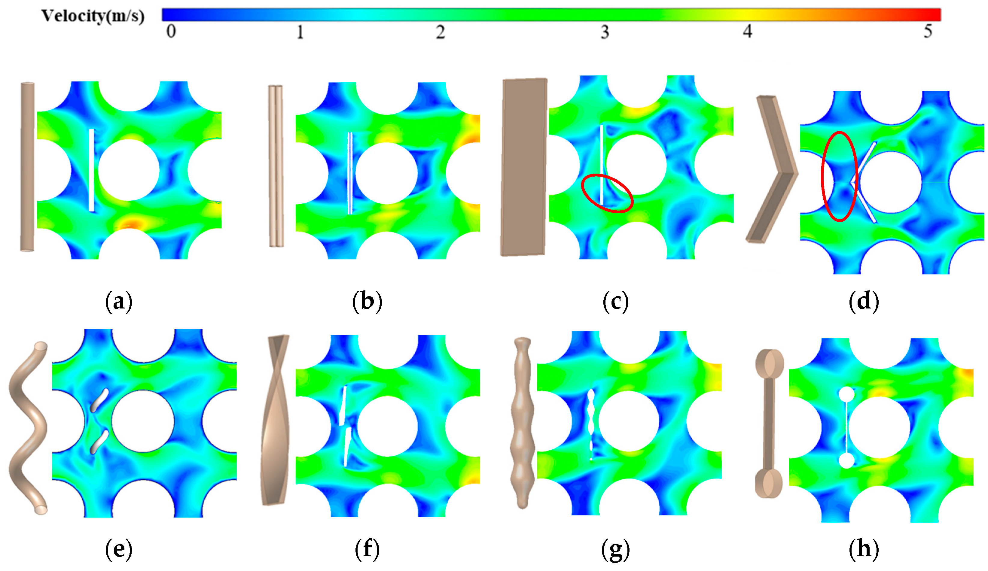
As shown in Figure 8, the flow fields around foreign objects of different shapes exhibit distinct characteristics, with the primary regions of flow separation and vortex shedding highlighted by red circles. The cylindrical object maintains relatively stable flow attachment with a narrow and symmetric wake. The square object induces early flow separation at its sharp edges, leading to stronger velocity fluctuations. The helical object exhibits coupled axial and transverse velocity components, forming a periodic and layered wake structure, which causes the most pronounced interference with the inter-tube flow. Irregular 1, whose geometry resembles a distorted cylinder, exerts a relatively minor influence on the surrounding flow, whereas irregular 2, featuring a plate-like midsection with a larger drag area, produces stronger flow disturbances similar to those observed for the plate-shaped object.

4.2. Lift Forces and Drag Forces Analysis

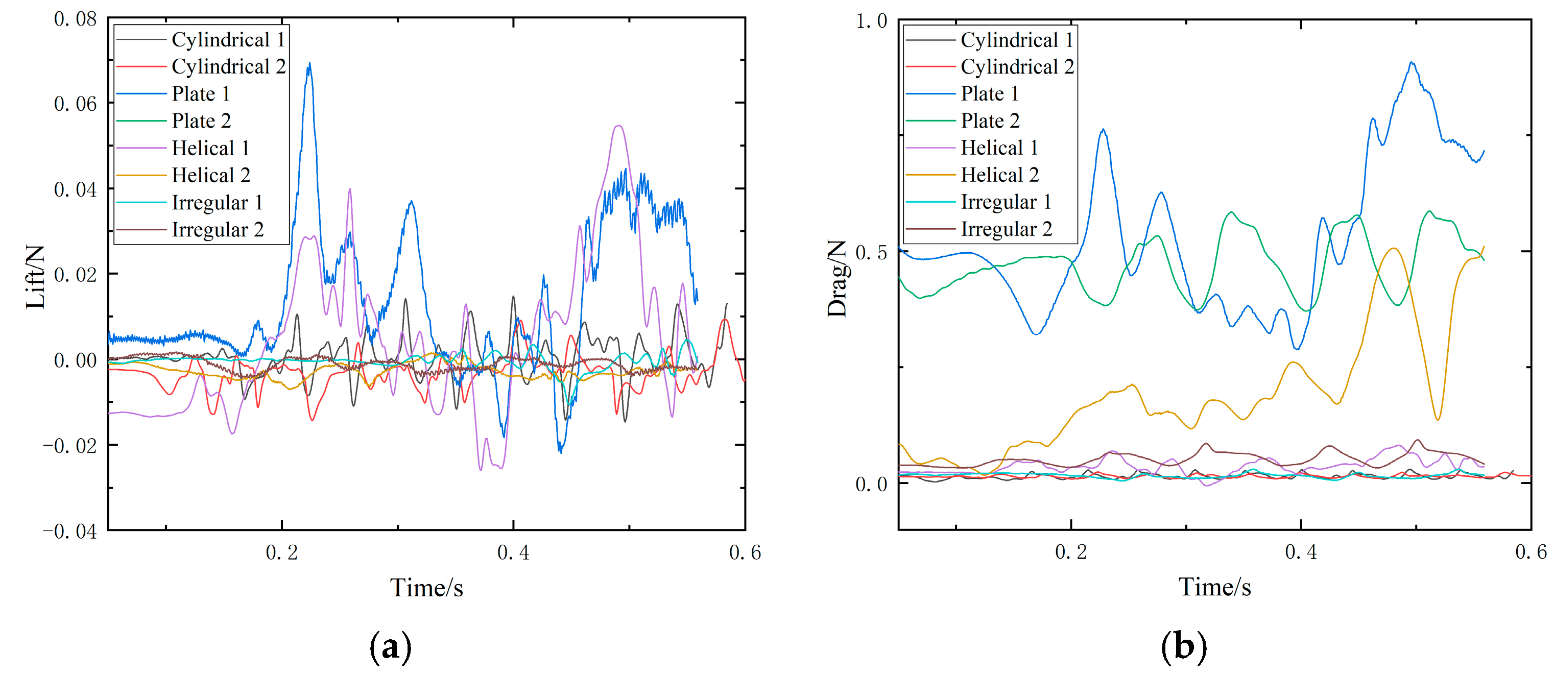
Figure 9 illustrates the lift forces and drag forces characteristics of foreign objects with different shapes. Results (Table 6) indicate that the fluctuation amplitude of lift forces and drag is strongly influenced by geometry. Cylindrical objects show the most stable response, with lift forces and drag forces standard deviations of 3.28 × 10⁻⁴–3.75 × 10⁻³ N and 3.65 × 10⁻³–1.48 × 10⁻² N, respectively, suggesting periodic yet stable vortex shedding. Plate-shaped objects exhibit the largest drag fluctuations (up to 1.61 × 10⁻¹ N), primarily due to their large lift-to-drag area ratio and strong flow separation at sharp edges. Helical objects show moderate fluctuations, where the superposition of axial and transverse vortices enhances lift forces and drag variations (lift forces ≈ 1.47–1.97 × 10⁻² N). Helical-2, being essentially a twisted plate, inherits a relatively high drag feature. Irregular objects display non-periodic force responses with smaller amplitudes, reflecting asymmetric and unstable wake structures arising from their composite cylindrical geometries. Overall, flow separation and wake symmetry induced by shape have a pronounced effect on unsteady aerodynamic forces, with plate and helical geometries being the most sensitive to flow perturbations.
These variations in aerodynamic loading directly affect the displacement response and vibration behavior of the foreign objects, forming the basis for the subsequent analysis.

4.3. Displacement Analysis

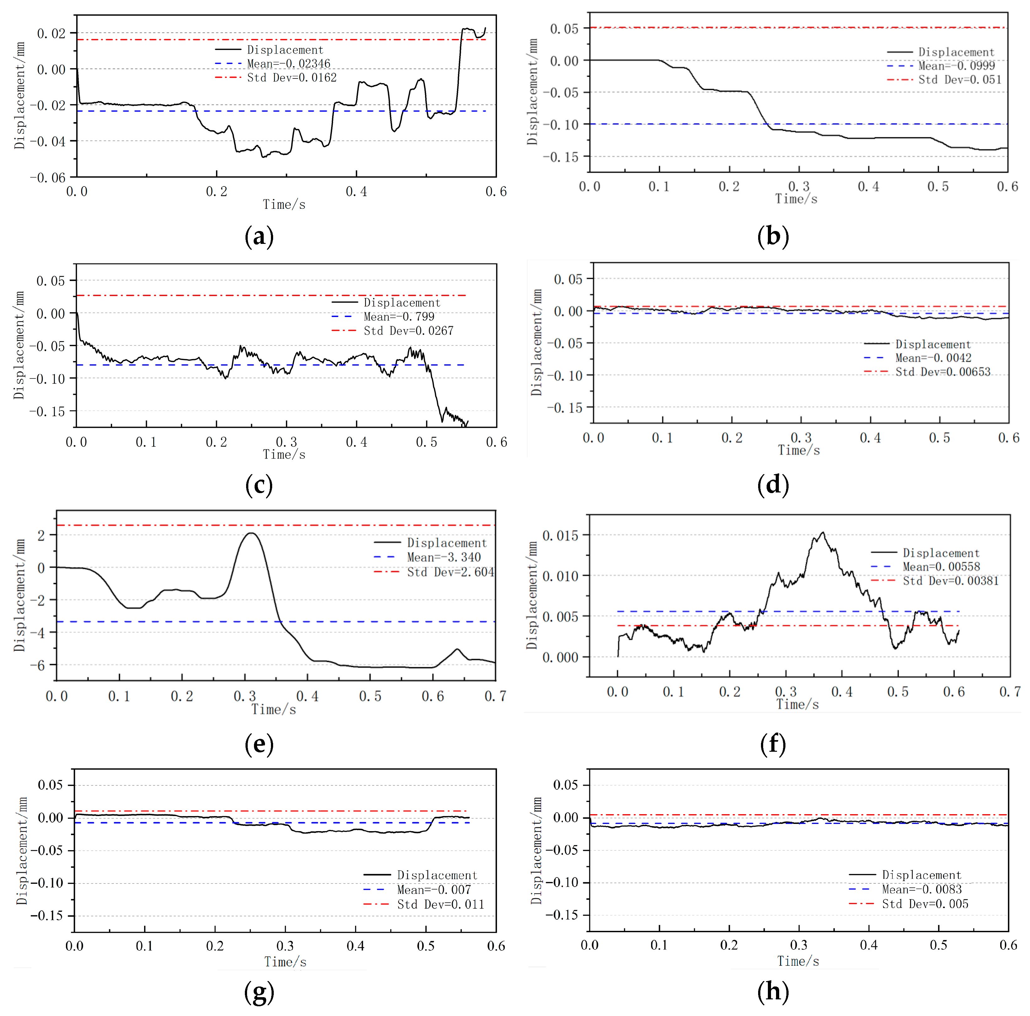
Figure 10 shows the displacement time histories for foreign objects of different shapes. The results indicate significant differences in both mean displacement and fluctuation amplitude among the various geometries. Cylindrical and plate-shaped objects exhibit relatively small displacements, with mean values ranging from −0.10 to −0.02 mm and standard deviations below 0.05 mm, characterized by low-frequency, primarily unidirectional, and relatively stable motion. Among them, Plate 2 demonstrates the most stable displacement, with a standard deviation of only 6.53 × 10⁻³ mm. This stability is mainly attributed to its larger drag area and the two symmetric contact points, which create a force balance and effectively limit the vibration degrees of freedom.
Helical objects show notably larger displacement amplitudes. Helical 1 reaches a mean displacement of −3.34 mm with a standard deviation of 2.60 mm, far exceeding the values observed for other shapes. This behavior indicates that the helical geometry induces complex axial–radial coupled vibrations, which may lead to rotation or oscillation in real flow conditions. Helical 2 exhibits relatively stable displacement (standard deviation of 3.81 × 10⁻³ mm), which is related to its nature as a twisted plate-like structure and relatively weak vortex shedding. Irregular objects show small displacement amplitudes (mean around −7 × 10⁻³ mm) with limited fluctuations, consistent with their lift forces and drag forces characteristics. Due to similar drag areas and lack of significant twisting, their overall dynamic behavior is closer to that of cylindrical objects.
Overall, the geometry of foreign objects significantly affects their displacement responses by altering the distribution of flow-induced forces and contact constraints. Among the shapes studied, helical structures are most sensitive to flow disturbances, exhibiting stronger vibration responses.

5. Discussion on the Influence of Foreign Object Geometry on Flow-Induced Vibrations

The results presented in Section 4 indicate that the geometry of foreign objects plays a critical role in determining their flow-induced vibration characteristics. By analyzing the displacement and force data (Figure 9 and Figure 10, Table 6), the underlying mechanisms of motion can be better understood.
The corresponding mean and standard deviation of displacement for each object are summarized in Table 7.
Cylindrical objects exhibit relatively small lift and drag forces and stable displacement responses. For instance, Cylindrical 1 and Cylindrical 2 show lift standard deviations of 3.28 × 10⁻⁴ N and 3.75 × 10⁻³ N, respectively, and drag standard deviations of 1.48 × 10⁻² N and 3.65 × 10⁻³ N (Table 6). Their displacement standard deviations remain below 0.05 mm (Figure 10a–b). This stable behavior is attributed to their symmetric drag areas, which produce balanced hydrodynamic forces along the primary vibration direction and minimize transverse fluctuations. Similarly, irregular objects, with comparable drag areas and no significant twisting, display mean displacements around −7 × 10⁻³ mm and limited fluctuations (Figure 10g–h), resulting in overall motion patterns close to those of cylindrical objects.
Plate-shaped objects demonstrate different behavior due to their large drag areas relative to the lift area. The enhanced frictional resistance limits the displacement, leading to more constrained motion. Among the plate objects, Plate 2 exhibits the most stable displacement, with a standard deviation of only 6.53 × 10⁻³ mm (Figure 10d), primarily due to its larger drag area and the presence of two symmetric contact points. These features create a force balance. As a result, the vibration degrees of freedom are effectively restricted. Plate 1 shows slightly larger fluctuations (standard deviation of 1.64 × 10⁻² N for lift forces and 1.61 × 10⁻¹ N for drag forces, Table 6; displacement in Figure 10c) due to its higher lift-to-drag ratio and stronger flow separation at sharp edges.
Helical objects display the most complex dynamic responses, with larger displacement amplitudes and greater variability. Helical 1 reaches a mean displacement of −3.34 mm with a standard deviation of 2.60 mm (Figure 10e), significantly higher than other shapes. The complex axial and radial coupling generated by the helical geometry, along with superposed vortical structures (Figure 8e), induces strong oscillatory motion. In contrast, Helical 2, which can be regarded as a twisted plate, exhibits relatively stable motion with a standard deviation of 3.81 × 10⁻³ mm (Figure 10f) and lift forces/drag forces fluctuations of 1.97 × 10⁻² N and 2.36 × 10⁻² N, respectively (Table 6). This suggests that the local geometry and structural twisting can mitigate the sensitivity to flow-induced perturbations, reducing the amplitude of vibration compared to fully helical structures.
Overall, the interplay between drag area, lift distribution, and geometric complexity governs the flow-induced vibration behavior of foreign objects. Symmetric or uniformly shaped objects (cylindrical and irregular) tend to produce small and stable displacements, while complex geometries such as helical shapes amplify coupled oscillations and lead to larger vibration amplitudes.
In addition, this study has several limitations. The displacement can be relatively large (exceeding 2 cm) because the model considers only dynamic friction and lacks structural constraints, such as tube sheets, to restrict object motion. The analysis currently covers only a subset of typical object shapes, and does not encompass all possible geometries. Systematic investigation of object size effects remains incomplete, and the modeling of multi-degree-of-freedom object motion requires further refinement to more accurately capture the complex dynamic responses under realistic operating conditions.

6. Conclusions

This study systematically investigated the flow-induced vibration behavior of secondary-side foreign objects in steam generator tube bundles, highlighting the critical influence of object geometry on displacement responses, lift forces and drag forces fluctuations, and flow field characteristics. The findings provide a valuable reference for predicting vibration behavior, assessing wear risks, and ensuring the safe operation of steam generators. Key conclusions are summarized as follows:
  • Validation of Numerical Methodology: A three-dimensional fluid–structure interaction (FSI) simulation framework, combining CFD with a single-degree-of-freedom rigid-body model, was established. Comparison with EPRI data demonstrates that the proposed approach reliably captures the unsteady flow forces and displacement responses of foreign objects, with deviations within acceptable limits.
  • Impact of Object Geometry on Flow-Induced Forces: The shape of foreign objects significantly affects flow separation, vortex shedding, and force fluctuations. Cylindrical and irregular objects produce relatively stable and low-amplitude lift and drag forces, whereas plate-shaped objects exhibit higher drag fluctuations due to large projected areas and symmetric contact points. Helical objects generate complex, coupled axial–radial vortices, leading to the most pronounced force variations.
  • Displacement Response Characteristics: Geometry governs vibration amplitude and patterns. Cylindrical and irregular objects maintain small, stable displacements; plate-shaped objects show constrained motion due to drag area and symmetric contacts; helical objects experience the largest oscillations, reflecting coupled translational and rotational motions induced by their complex geometry.
  • Implications for Steam Generator Safety: The interplay between drag area, lift distribution, and geometric complexity is key to understanding secondary-side foreign object behavior. Symmetric or simple-shaped objects lead to predictable, low-risk vibrations, while complex geometries like helical shapes amplify coupled oscillations, increasing wear potential. These findings provide a valuable reference for assessing the dynamic behavior of foreign objects in steam generators.

Author Contributions

Conceptualization, G.Z. and H.W.; methodology, Y.H. and H.W.; numerical modeling and simulation, Y.H., B.Z. and Z.C.; validation, Y.H., Y.L. and H.W.; formal analysis, Y.H. and Y.L.; investigation, Y.H., Z.C. and J.M.; resources, B.Z. and J.M.; data curation, Y.H.; writing—original draft preparation, Y.H.; writing—review and editing, H.W. and G.Z.; visualization, Y.H.; supervision, G.Z.; project administration, G.Z.; funding acquisition, G.Z. All authors have read and agreed to the published version of the manuscript.

Funding

This research received the funding support from China General Nuclear Power Group Peak Plan Project 3100173757.

Data Availability Statement

The data presented in this study are available on request from the corresponding author due to restrictions related to the ongoing research.

Acknowledgments

The authors would like to thank the Suzhou Nuclear Power Research Institute and Yangjiang Nuclear Power Co., Ltd. for their technical and computational support. The authors also thank Tianjin University for providing access to numerical simulation facilities. The authors have reviewed and edited all generated content and take full responsibility for the final manuscript.

Conflicts of Interest

Authors Yuhua Hang, Zhen Cai, Bin Zhu and Jinna Mei were employed by the Suzhou Nuclear Power Research Institute. Author Yuanqing Liu was employed by Yangjiang Nuclear Power Co., Ltd. The remaining authors declare that the research was conducted in the absence of any commercial or financial relationships that could be construed as a potential conflict of interest.

References

  1. Hanbo, L.I.N.; Lichen, T.A.N.G.; Hao, Q.I.A.N.; Runluo, C.H.E.N.; Changxun, W.A.N.G.; Linjun, X.I.E. Fretting fatigue test and damage mechanism analysis of nuclear power 690 for alloy heat transfer tube. Tribology 2022, 42, 954–965. [Google Scholar]
  2. Wang, J.; Yang, C.; Zhang, L.; Meng, F.; Shi, X. Pitting corrosion resistance of alloy 690TT for steam generation heat exchanger tube. Corros. Prot. 2016, 37, 821–825. Available online: https://fsyfh.mat-test.com/cn/article/doi/10.11973/fsyfh-201610009 (accessed on 16 July 2024).
  3. Li, Z.H.; Lu, Y.H.; Hong, C.; Zhao, Y.G.; Zhang, W.D.; Shoji, T. Effects of foreign object damage on high-cycle fatigue behavior of Inconel Alloy 690TT steam generator tubes. Eng. Fract. Mech. 2023, 292, 109660. [Google Scholar] [CrossRef]
  4. Mu, D.; Rong, J.; Wang, M.; Tian, W.; Qiu, S.; Su, G. Investigating the Motion Characteristics of Complex-Shaped Foreign Objects on the Secondary Side of a Steam Generator Based on CFD-DEM Method. In International Conference on Nuclear Engineering; American Society of Mechanical Engineers: New York, NY, USA, 2024; Volume 88315, p. V011T15A056. [Google Scholar]
  5. Zhong, X.; Han, E.H.; Wu, X. Corrosion behavior of alloy 690 in aerated supercritical water. CorrosionScience 2013, 66, 369–379. [Google Scholar] [CrossRef]
  6. Zhang, Y.; Ming, H.; Tang, L.; Wang, J.; Qian, H.; Han, E.H. Effect of the frequency on fretting corrosion behavior between alloy 690TT tube and 405 stainless steel plate in high-temperature pressurized water. Tribol. Int. 2021, 164, 107229. [Google Scholar] [CrossRef]
  7. Zhongliang, M.A. Corrosion and protection mechanism of 690 alloy heat tube for steam generator. Mater. Prot. 2019, 52, 133–137. Available online: https://link.cnki.net/doi/10.16577/j.cnki.42-1215/tb.2019.06.024 (accessed on 16 July 2024). (In Chinese).
  8. Guo, X.; Lai, P.; Li, L.; Tang, L.; Zhang, L. Progress in studying the fretting wear/corrosion of nuclear steam generator tubes. Ann. Nucl. Energy 2020, 144, 107556. [Google Scholar] [CrossRef]
  9. Bian, W.W.; Hong, C.; Xin, L.; Kang, L.Z.; Han, Y.M.; Liu, H.; Shoi, T.; Lu, Y.H. Effect of the cycle number on fretting wear behavior of alloy 690TT tube in high-temperature pressurized water. J. Nucl. Mater. 2022, 567, 153828. [Google Scholar] [CrossRef]
  10. Yun, J.Y.; Park, M.C.; Shin, G.S.; Heo, J.H.; Kim, D.I.; Kim, S.J. Effects of amplitude and frequency on the wear mode change of Inconel 690 SG tube mated with SUS 409. Wear 2014, 313, 83–88. [Google Scholar] [CrossRef]
  11. Soria, S.R.; Tolley, A.; Yawny, A. Running condition and material response fretting maps of incoloy 800 steam generator tube sagainst AISI 304L pads in air and room temperature. Tribol. Int. 2019, 135, 408–420. [Google Scholar] [CrossRef]
  12. Mahey. Flow-Induced Vibrations of Foreign Objects Inside Steam Generator’s Tube Bundle. Ph.D. Thesis, University of Waterloo, Waterloo, ON, Canada, 2017.
  13. Kima; Choa. Predicted wear on the tube outside surface due to foreign object in the secondary side of steam generator. In Proceedings of the KNS Autumn Meeting, Kyoungju, Republic of Korea, 24–26 October 2012; p. 2. [Google Scholar]
  14. Mureithi; Cucuel; Saber-Cherif; Olala; Ashrafi. Characteristics of Turbulence and Drag Forces on Foreign Objects in Tube Arrays. In Pressure Vessels and Piping Conference; American Society of Mechanical Engineers: New York, NY, USA, 2016; Volume 50404, p. V004T04A018. [Google Scholar]
  15. Zhipeng, F.; Yixiong, Z.; Xuan, H.; Shuai, L.; Huanhuan, Q.; Fengchun, C. Fluid-structure Interaction Simulation and Data-driven Modeling of Tube Bundle Based on OpenFOAM. Nucl. Power Eng. 2022, 43, 158–164. [Google Scholar]
  16. Sun, J.; Sun, R.; Qiao, P.; Tan, S.; Tian, R. Numerical Study of Flow-induced Vibration in Square Tube Bundle Structures. At. Energy Sci. Technol. 2025, 59, 1044–1054. [Google Scholar]
  17. Ding, Z.; Bai, X.; Zhai, Y.; Yang, J.; Liu, D.; Yang, Y.; Tang, D. Numerical simulation research on the vibration of helical tube arrays under transverse flow. Energies 2022, 15, 9082. [Google Scholar] [CrossRef]
  18. EPRI. Steam Generator Management Program: Steam Generator Foreign Object Wear Estimation Model-Volume I: Fundamental Model and Simulation Results. 2017. Available online: https://www.epri.com/research/products/000000000001019039 (accessed on 16 July 2024).
  19. EPRI, Steam Generator Management Program: Foreign Object Prioritization Strategy for Triangular Pitch Steam Generators. 2010. Available online: https://www.epri.com/research/products/000000000001020989 (accessed on 30 July 2024).
  20. Bernard, J.E. The simulation of Coulomb friction in mechanical systems. Simul. Trans. Soc. Model. Simul. Int. 1980, 34, 11–16. [Google Scholar] [CrossRef]
  21. Pennestrì, E.; Rossi, V.; Salvini, P.; Valentini, P.P. Review and comparison of dry friction force models. Nonlinear Dyn. 2016, 83, 1785–1801. [Google Scholar] [CrossRef]
  22. Rathee, R. Numerical modeling and simulation of friction models for mechanical systems: A brief review. Mater. Today: Proc. 2023. [Google Scholar] [CrossRef]
  23. Liu, Y.; Chen, J.; Zhao, Q.; Tian, F.; Peng, W.; Xia, P. Migration and Distribution of Objects in Steam Generators Secondary Side at Pressurized Water Reactor Nuclear Power Plants. Energy Res. Manag. 2025, 17, 17-22+189. Available online: https://link.cnki.net/doi/10.16056/j.2096-7705.2025.03.003 (accessed on 16 July 2024). (In Chinese).
  24. Hao, W.U.; Wei, T.A.N.; Qing-de, N. A numerical model for fluid-elastic instability of a square tube array. J. Vib. Shock 2013, 32, 102–106. [Google Scholar]
  25. Rodriguez, A.; Adansi, R.; Enriquez, A.; Habib, N.; Olvera, G.; Love, N.; Kumar, V. Reynolds Numbers: The K-epsilon (k-e) Turbulence Model vs. Laminar Model for Flow Over a Circular Cylinder. Preprint 2021, 3–22. [Google Scholar] [CrossRef]
  26. Wilcox, D.C. Turbulence Modeling for CFD; DCW Industries Inc.: La Canada, CA, USA, 2006. [Google Scholar]
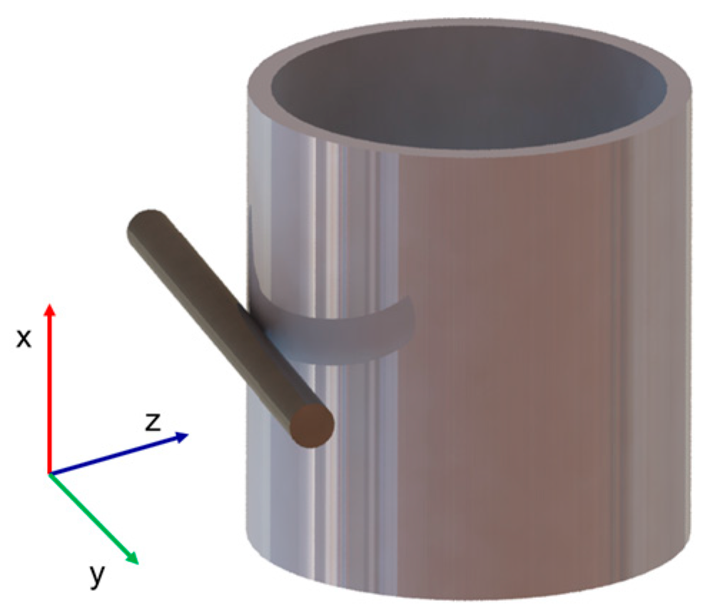
Figure 1. Motion relationship between foreign objects and heat transfer tubes.
Jne 06 00047 g001
Figure 2. Dynamic contact model of the foreign object and heat transfer tubes.
Jne 06 00047 g002
Figure 3. Schematic diagram of foreign bodies with different shapes: (a) Cylindrical 1; (b) Cylindrical 2; (c) Plate 1; (d) Plate 2; (e) Helical 1; (f) Helical 2; (g) Irregular1; (h) Irregular2.
Jne 06 00047 g003
Figure 4. Establishment of the three-dimensional model.
Jne 06 00047 g004
Figure 5. Grid partition.
Jne 06 00047 g005
Figure 6. CFX simulation setup.
Jne 06 00047 g006
Figure 7. Comparison of simulated and EPRI results for lift forces, drag forces, and displacement.
Jne 06 00047 g007
Figure 8. Comparison of lift force time domain curves: (a) Cylindrical 1; (b) Cylindrical 2; (c) Plate 1; (d) Plate 2; (e) Helical 1; (f) Helical 2; (g) Irregular 1; (h) Irregular 2.
Jne 06 00047 g008
Figure 9. Lift forces and drag forces analysis for different foreign object shapes: (a) Lift; (b) Drag.
Jne 06 00047 g009
Figure 10. Displacement time history for different foreign object shapes: (a) Cylindrical 1; (b) Cylindrical 2; (c) Plate 1; (d) Plate 2; (e) Helical 1; (f) Helical 2; (g) Irregular 1; (h) Irregular 2.
Jne 06 00047 g010
Table 1. Heat transfer tube parameters.
ParametersNumerical Values
tube diameter (mm)19.05
pitch-to-diameter Ratio1.44
arrangementSquare arrangements
span (mm)900
wall thickness (mm)1.09
unit mass (kg)0.72
materialAlloy 690
density (kg/m3)8140
Poisson’s ratio0.289
elastic modulus (GPa)211
Table 2. Foreign object parameters.
ParametersNumerical Values
diameter (mm)2
Length (mm)25.4
shapecylindrical, square, helical, irregular
position0.1 mm in front of the heat transfer tube
materialAlloy 690
friction coefficient0.3
density (kg/m3)8140
Table 3. Grid independence verification.
Grid Size (mm)Number of MeshMean Drag Force (N)Percentage
Difference (%)
0.0511,621,6020.199
0.16,893,2150.2011.00
0.35,630,8540.1952.01
0.54,539,3510.1914.02
1.01,429,0340.2168.54
Table 4. Simulation parameter settings.
ParametersSetting
Analysis TypeTransient Analysis
Analysis Duration0.6 s
Time Step0.0005 s
Inlet ConditionUniform inflow
Outlet ConditionZero-pressure outlet
Turbulence Modelk–ε model
Wall FunctionScalable wall function
Convergence ControlMinimum coefficient loops: 1; Maximum coefficient loops: 20
Residuals1 × 10−4
Inlet Velocity1 m/s
Fluid MaterialLiquid water (998 kg/m3)
Table 5. Comparison of simulated and EPRI results for lift forces, drag forces, and displacement.
CaseEPRIPresent SimulationPercentage
Difference (%)
Mean Lift (N)3.5 × 10−23.7 × 10−2−5.71%
Mean Drag (N)7.0 × 10−26.5 × 10−27.14%
Std Dev Lift (N)5.7 × 10−25.6 × 10−21.75%
Std Dev Drag (N)3.5 × 10−23.6 × 10−2−2.86%
Displacement (mm)7.96.5916.58%
Table 6. Mean and standard deviation of lift forces and drag forces for different shapes.
ShapeStd Dev Lift (×10−3 N)Std Dev Drag (×10−3 N)
Cylindrical 10.3314.8
Cylindrical 23.753.65
Plate 116.4161
Plate 21.8994.3
Helical 114.7017.8
Helical 219.7023.6
Irregular 12.425.89
Irregular 21.3218
Table 7. Mean and Standard Deviation of Displacements for Different Foreign Object Shapes.
ShapeStd Dev Displacement
(×10−2 mm)
Mean Displacement
(×10−2 mm)
Cylindrical 11.622.35
Cylindrical 25.1100
Plate 12.6780
Plate 20.6530.42
Helical 1260334
Helical 20.3810.558
Irregular 11.10.7
Irregular 20.50.83
Disclaimer/Publisher’s Note: The statements, opinions and data contained in all publications are solely those of the individual author(s) and contributor(s) and not of MDPI and/or the editor(s). MDPI and/or the editor(s) disclaim responsibility for any injury to people or property resulting from any ideas, methods, instructions or products referred to in the content.