
Spent Nuclear Fuel—Waste to Resource, Part 1: Effects of Post-Reactor Cooling Time and Novel Partitioning Strategies in Advanced Reprocessing on Highly Active Waste Volumes in Gen III(+) UOx Fuel Systems


Abstract
1. Introduction
- High-level waste (HLW) are typically defined as “appreciably heat generating”, meaning that active cooling is often required. In Germany, this means a heat output of > 200 W/m3 [5], which serves as a useful definition for this work. HLW includes materials such as spent nuclear fuel (SNF), reprocessing raffinates, some activated structural materials, etc., which must always be handled remotely due to their intense radiation fields, which are extremely hazardous if not lethal to unprotected humans, even after short exposure [5]. These wastes are often vitrified for long-term storage or disposal in a geological disposal facility (GDF), the latter of which has yet to be commercially realised anywhere at the time of writing [6].
- Intermediate-level waste (ILW) include materials such as the irradiated (zircalloy) cladding and structural elements from SNF assemblies, which are not appreciably heat-generating but nonetheless still highly radioactive. These require remote handling in shielded hot cells, but in contrast to HLW are typically prepared and stored for disposal in a cemented form without the necessity for continuous active cooling. Under UK legislation, ILW is defined as “neither HLW nor (very) low level waste”.
- Low-level waste (LLW) and very low-level waste (VLLW) are of sufficiently low activity that they can be handled outside hot cells, and include materials such as contaminated PPE, demolition rubble from nuclear facilities, and some peripheral nuclear plant hardware.
2. Methodology
2.1. Data Sources and Calculations
2.2. Consideration of Separation Operations and Processes
2.3. Spent Fuel Reprocessing Scenarios
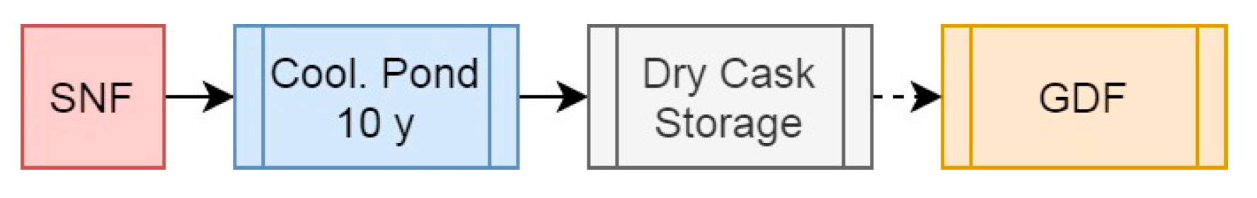
2.3.1. Scenario 1: The Open Fuel Cycle
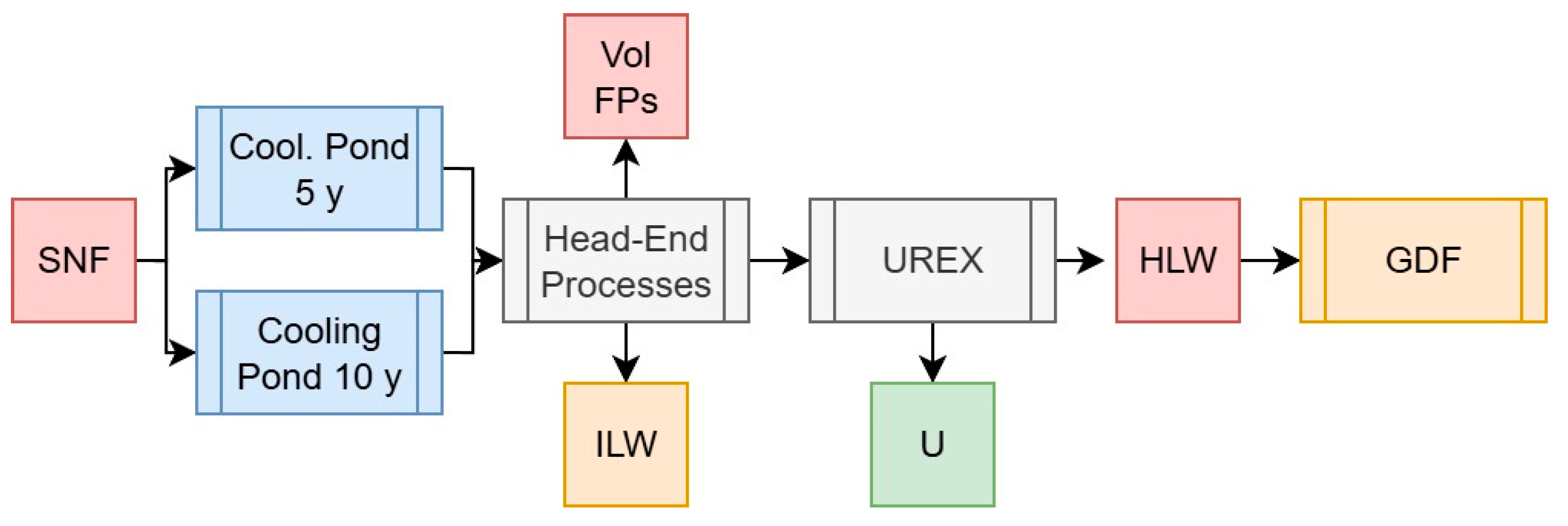
2.3.2. Scenario 2: UREX for Waste Volume Reduction and/or U Re-Enrichment
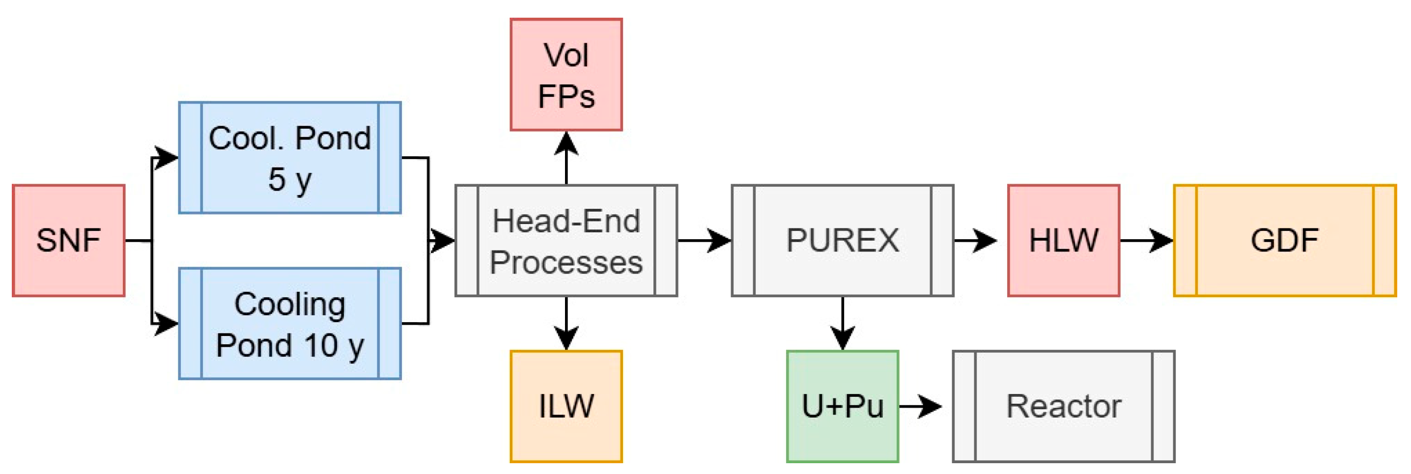
2.3.3. Scenario 3: The Traditional PUREX Process
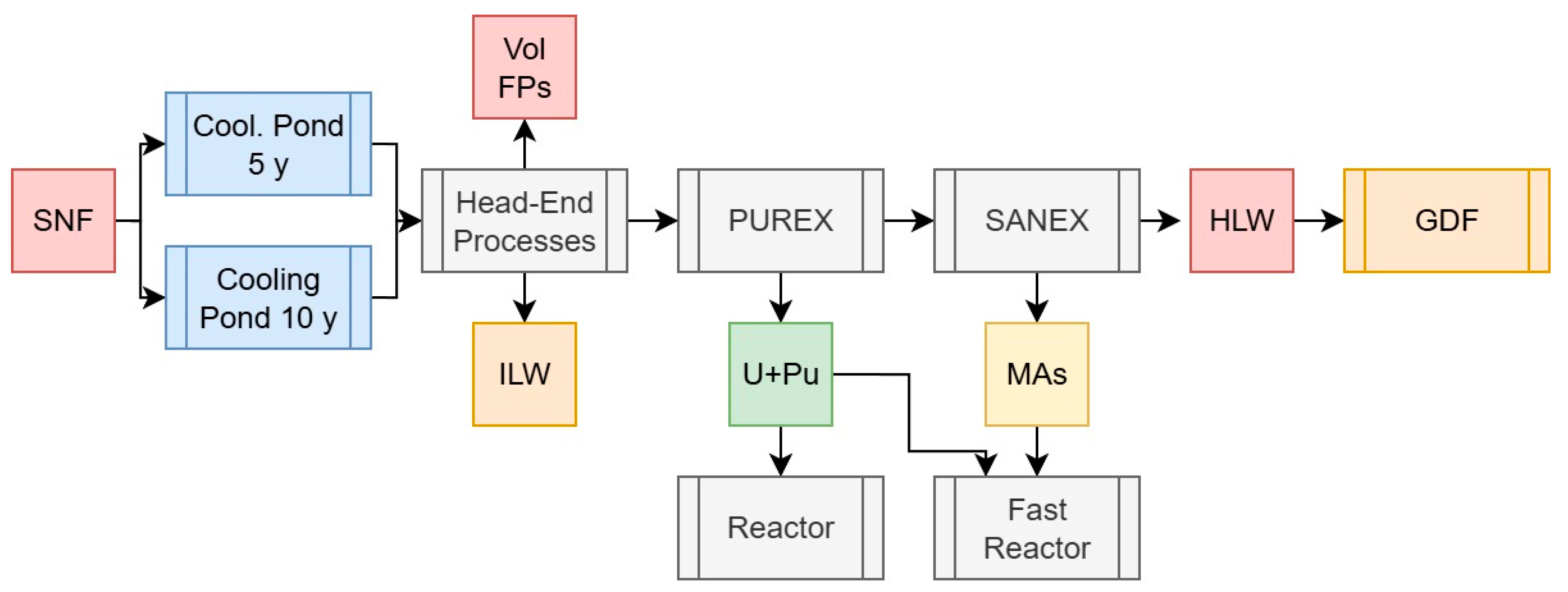
2.3.4. Scenario 4: PUREX with Minor Actinide Separations, GANEX, or UREX Versions
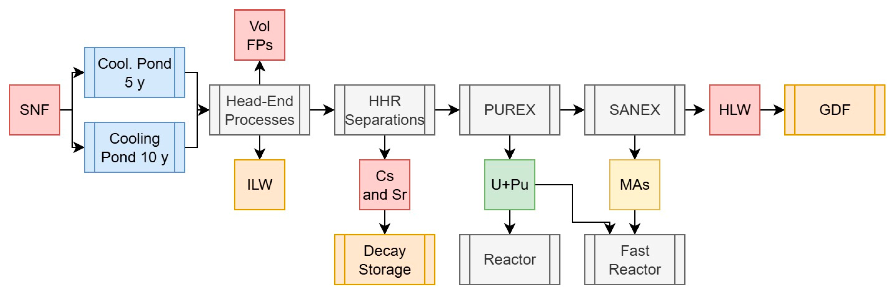
2.3.5. Scenario 5a: U, Pu, and Minor Actinide Separations with HHR Removal
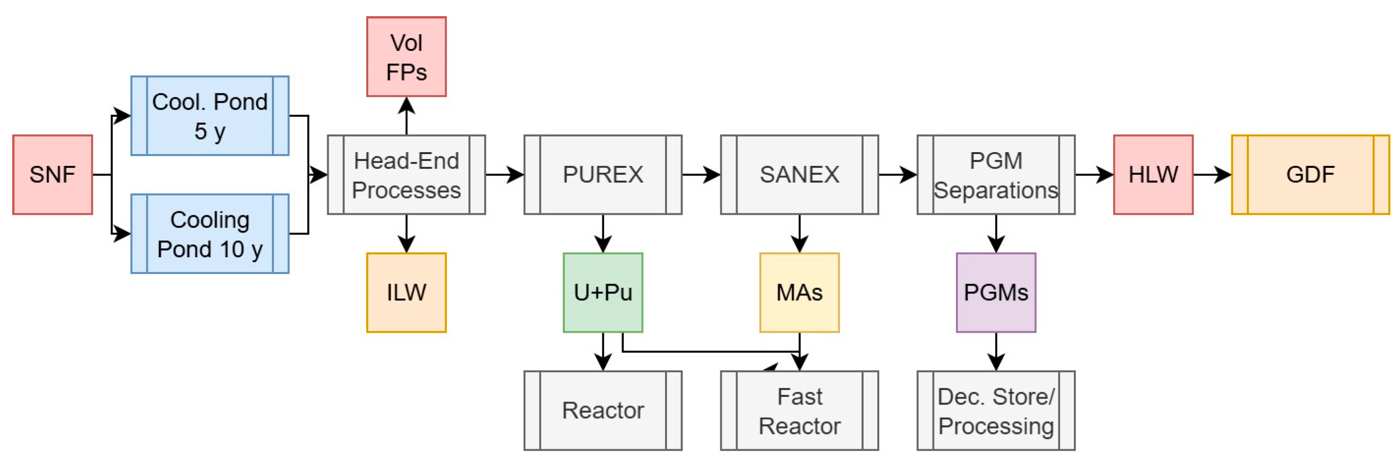
2.3.6. Scenario 5b: U, Pu, and Minor Actinide Separations with PGM Recovery
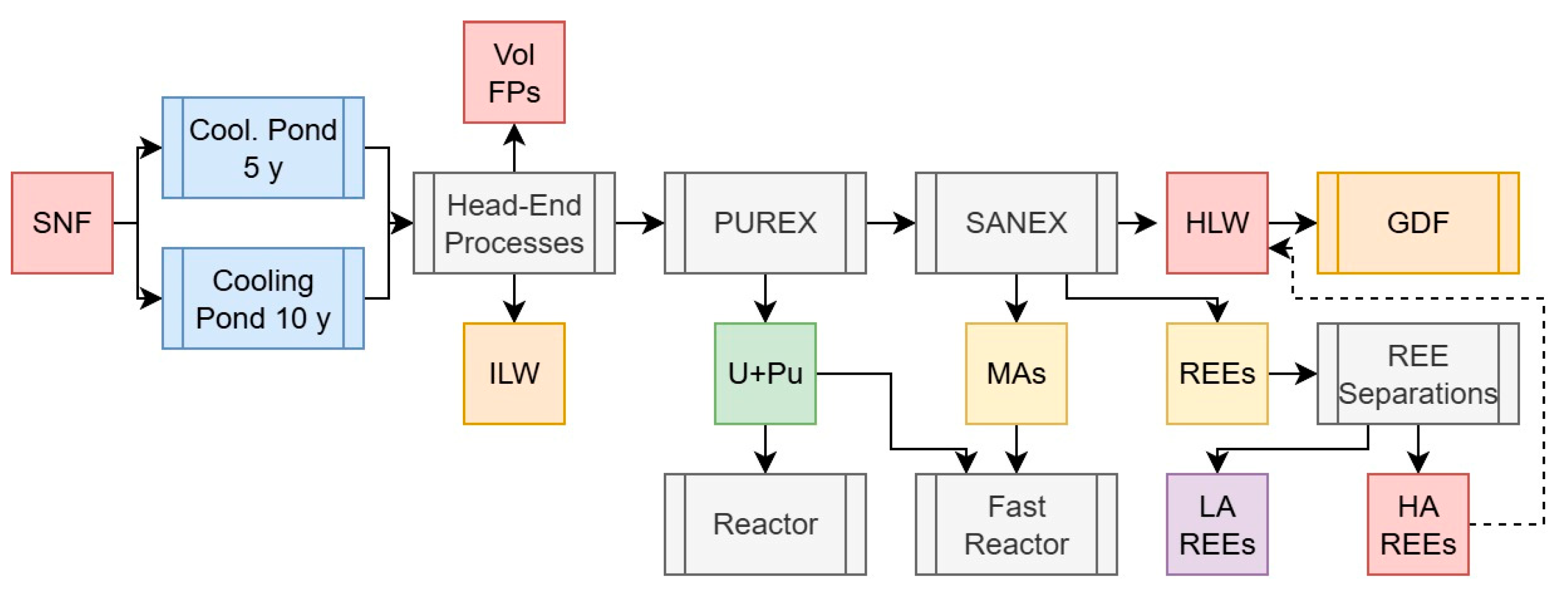
2.3.7. Scenario 5c: U, Pu, and Minor Actinide Separations with REE Recovery
3. Results and Discussion
3.1. Scenario 1: The Open Fuel Cycle
3.2. Scenario 2: The UREX Process
3.3. Scenario 3: The PUREX Process
3.4. Scenario 4: The PUREX Process with Minor Actinide Separations
3.5. Scenario 5a: High-Heat Radionuclide Separations in PUREX with Minor Actinide Separations
3.6. Scenario 5b: Platinum Group Metal Separations in PUREX with Minor Actinide Separations
3.7. Scenario 5c: Partitioning of Low-Activity Rare Earth Elements in PUREX with Minor Actinide Separations
- Yttrium, accounting for the bulk stable, naturally occurring 89Y and shorter-lived 88Y and 91Y. 90Y is discounted, as this is the short-lived daughter of 90Sr and would decay to extinction after several weeks.
- Lanthanum, accounting for the two naturally occurring isotopes 138La and 139La, the former of which is slightly radioactive but primordial.
- Praseodymium, accounting for the stable, naturally occurring 141Pr. The short-lived, high-energy daughters of 144Ce are discounted from this feed.
- Neodymium, accounting for the stable and/or primordial, long-lived radioactive (primordial) isotopes 142Nd, 143Nd, 144Nd, 145Nd, 146Nd, 148Nd, and 150Nd.
- Gadolinium, terbium, dysprosium, holmium, erbium, thulium, and ytterbium, representing the upper limit of fission yields decreasing across this series, all of which consist of mostly stable isotopes with very small fractions of radioactive species.
- Cerium, primarily from the decay of 144Ce and its short-lived daughter 144Pr, whose values are counted with this feed but would have decayed completely after ~20 y following removal from a reactor.
- Promethium, all of the isotopes of which are radioactive, with the longest half-life present in any significant quantity being 147Pm (t0.5 = 2.62 y).
- Samarium, which contains large quantities of the medium-lived (t0.5 = 90 y) isotope 151Sm, though the decay energy of this species is sufficiently low (76.7 keV), and is used in remote applications (i.e., catalysis), may be feasible.
- Europium, which contains quantities of the radioactive medium-lived isotopes 150Eu, 154Eu, and 155Eu.
3.8. Comparison of Waste Outputs from Different Spent Fuel Reprocessing Strategies
3.9. Direct and Indirect Value Recovery and Necessary Development
3.10. Implications for Future Reactors and Fuel Types
4. Conclusions
Supplementary Materials
Author Contributions
Funding
Data Availability Statement
Acknowledgments
Conflicts of Interest
Appendix A

| Element | Isotope(s) |
|---|---|
| Pb | 206Pb, 207Pb, 208Pb, 209Pb, 210Pb, 212Pb |
| Bi | 209Bi, 210mBi, 210Bi, 211Bi, 212Bi, 213Bi, 214Bi |
| Po | 210Po, 211Po, 212Po, 214Po, 215Po, 216Po, 218Po |
| At | 217At |
| Rn | 219Rn, 220Rn, 222Rn |
| Fr | 221Fr, 223Fr |
| Ra | 223Ra, 224Ra, 225Ra, 228Ra |
| Ac | 225Ac, 227Ac, 228Ac |
| Th | 227Th, 228Th, 229Th, 230Th, 231Th, 232Th, 234Th |
| Pa | 231Pa, 233Pa, 234mPa, 234Pa |
| U | 232U, 233U, 234U, 235U, 236U, 237U, 238U |
| Np | 236Np, 237Np, 238Np, 239Np, 240mNp |
| Pu | 236Pu, 238Pu, 239Pu, 240Pu, 241Pu, 242Pu, 243Pu, 244Pu |
| Am | 241Am, 242mAm, 242Am, 243Am, 245Am |
| Cm | 242Cm, 243Cm, 244Cm, 245Cm, 246Cm, 247Cm, 248Cm, 250Cm |
| Bk | 249Bk, 250Bk |
| Cf | 249Cf, 250Cf, 251Cf, 252Cf, 254Cf |
| Es | 254Es, 255Es |
| Element | Isotope(s) | Element | Isotope(s) |
|---|---|---|---|
| Zn | 66Zn, 67Zn, 68Zn, 70Zn | Sb | 121Sb, 123Sb, 124Sb, 125Sb, 126Sb |
| Ga | 69Ga, 71Ga | Te | 124Te, 125Te, 126Te, 127mTe, 128Te, 129mTe, 130Te |
| Ge | 70Ge, 72Ge, 73Ge, 74Ge, 76Ge | I | 127I, 129I |
| As | 75As | Xe | 128Xe, 129Xe, 130Xe, 131Xe, 132Xe, 134Xe, 136Xe |
| Se | 76Se, 77Se, 78Se, 79Se, 80Se, 82Se | Cs | 133Ce, 134Ce, 135Ce, 137Ce |
| Br | 79Br, 81Br | Ba | 134Ba, 135Ba, 136Ba, 137mBa, 138Ba |
| Kr | 81Kr, 82Kr, 83Kr, 84Kr, 85Kr, 86Kr | La | 138La, 139La |
| Rb | 85Rb, 87Rb | Ce | 139Ce, 140Ce, 141Ce, 142Ce, 144Ce |
| Sr | 84Sr, 86Sr, 88Sr, 89Sr, 90Sr | Pr | 141Pr, 144Pr |
| Y | 88Y, 89Y, 90Y, 91Y | Nd | 142Nd, 143Nd, 144Nd, 145Nd, 146Nd, 148Nd, 150Nd |
| Zr | 90Zr, 91Zr, 92Zr, 93Zr, 94Zr, 95Zr, 96Zr | Pm | 146Pm, 147Pm, 148mPm, 148Pm |
| Nb | 92Nb, 93mNb, 93Nb, 94Nb, 95mNb, 95Nb | Sm | 146Sm, 147Sm, 148Sm, 149Sm, 150Sm, 151Sm, 152Sm, 154Sm, |
| Mo | 95Mo, 96Mo, 97Mo, 98Mo, 100Mo | Eu | 150Eu, 151Eu, 152Eu, 153Eu, 154Eu, 155Eu |
| Tc | 98Tc, 99Tc | Gd | 152Gd, 153Gd, 154Gd, 155Gd, 156Gd, 157Gd, 158Gd, 160Gd |
| Ru | 99Ru, 100Ru, 101Ru, 102Ru, 103Ru, 104Ru, 106Ru | Tb | 159Tb, 160Tb |
| Rh | 102Rh, 103mRh, 103Rh, 106Rh | Dy | 160Dy, 161Dy, 162Dy, 163Dy, 164Dy |
| Pd | 102Pd, 104Pd, 105Pd, 106Pd, 107Pd, 108Pd, 110Pd | Ho | 165Ho, 166mHo |
| Ag | 107Ag, 109mAg, 109Ag, 110mAg | Er | 166Er, 167Er, 168Er, 170Er |
| Cd | 110Cd, 111Cd, 112Cd, 113mCd, 113Cd, 114Cd, 116Cd | Tm | 169Tm, 170Tm, 171Tm |
| In | 115In, 115mIn, 115In | Yb | 168Yb, 169Yb, 170Yb, 171Yb, 172Yb |
| Sn | 116Sn, 117Sn, 118Sn, 119Sn, 120Sn, 122Sn, 124Sn, 126Sn |
References
- World Nuclear Association. World Nuclear Association. Radioactive Waste Management. WNA. 2002. Available online: https://world-nuclear.org/information-library/nuclear-fuel-cycle/nuclear-waste/radioactive-waste-management (accessed on 24 March 2025).
- Holdsworth, A.F.; Ireland, E. Navigating the Path of Least Resistance to Sustainable, Widespread Adoption of Nuclear Power. Sustainability 2024, 16, 2141. [Google Scholar] [CrossRef]
- Boscarino, J.E. From Three Mile Island to Fukushima: The impact of analogy on attitudes toward nuclear power. Policy Sci. 2019, 52, 21–42. [Google Scholar] [CrossRef]
- IAEA-TECDOC-1587; Spent Fuel Reprocessing Options. International Atomic Energy Agency: Vienna, Austria, 2008. Available online: https://www-pub.iaea.org/MTCD/Publications/PDF/TE_1587_web.pdf (accessed on 24 July 2025).
- IAEA Nuclear Energy Series NW-T-1.14 (Rev 1). Status and Trends in Spent Fuel and Radioactive Waste Management, Annex I–VII; International Atomic Energy Agency: Vienna, Austria. 2022; Available online: https://www-pub.iaea.org/MTCD/Publications/PDF/PUB1963_web.pdf and https://www-pub.iaea.org/MTCD/Publications/PDF/SupplementaryMaterials/PUB1963-ANNEXES-I-VII.pdf (accessed on 24 July 2025).
- South Copeland GDF Community Partnership. International Focus: Sweden. 2024. Available online: https://southcopeland.workinginpartnership.org.uk/international-focus-sweden/ (accessed on 24 March 2025).
- Sun, X.Y.; Han, L.H.; Li, X.X.; Hu, B.L.; Luo, W.; Liu, L. Transmutation of MAs and LLFPs with a lead-cooled fast reactor. Sci. Rep. 2023, 13, 1693. [Google Scholar] [CrossRef]
- Holdsworth, A.F.; Eccles, H.; Sharrad, C.A.; George, K. Spent Nuclear Fuel—Waste or Resource? The Potential of Strategic Materials Recovery during Recycle for Sustainability and Advanced Waste Management. Waste 2023, 1, 249–263. [Google Scholar] [CrossRef]
- Allison, W. We Should Stop Running Away from Radiation. Philos. Technol. 2011, 24, 193–195. [Google Scholar] [CrossRef]
- Vandenborre, J.; Guillonneau, S.; Blain, G.; Haddad, F.; Truche, L. From nuclear waste to hydrogen production: From past consequences to future prospect. Int. J. Hydrogen Energy 2024, 64, 65–68. [Google Scholar] [CrossRef]
- Forsberg, C.W. Rethinking High-Level Waste Disposal: Separate Disposal of High-Heat Radionuclides (90Sr and 137Cs). Nucl. Technol. 2000, 131, 252–268. [Google Scholar] [CrossRef]
- Rohrmann, C.A. Values in Spent Fuel from Power Reactors; Report No. BNWL-25; Pacific Battelle Northwest Labs: Richland, WA, USA, 1965. [Google Scholar]
- Bond, G.; Eccles, H.; Kavi, P.C.; Holdsworth, A.F.; Rowbotham, D.; Mao, R. Removal of Cesium from Simulated Spent Fuel Dissolver Liquor. J. Chromatogr. Sep. Tech. 2019, 10, 417. [Google Scholar]
- Holdsworth, A.F.; Eccles, H.; Rowbotham, D.; Bond, G.; Kavi, P.C.; Edge, R. The Effect of Gamma Irradiation on the Ion Exchange Properties of Caesium-Selective Ammonium Phosphomolybdate-Polyacrylonitrile (AMP-PAN) Composites under Spent Fuel Recycling Conditions. Separations 2019, 6, 23. [Google Scholar] [CrossRef]
- Holdsworth, A.F.; Eccles, H.; Rowbotham, D.; Brookfield, A.; Collison, D.; Bond, G.; Kavi, P.C.; Edge, R. The Effect of Gamma Irradiation on the Physiochemical Properties of Caesium-Selective Ammonium Phosphomolybdate–Polyacrylonitrile (AMP–PAN) Composites. Clean. Technol. 2019, 1, 294–310. [Google Scholar] [CrossRef]
- Holdsworth, A.F.; Eccles, H.; George, K.; Sharrad, C.A. Heterogeneous Separations of Highly Active Radionuclides for Advanced Decay Heat & Waste Management in Next-Generation Spent Fuel Recycling/Reprocessing. In Proceedings of the 4th Cloud Conference: Nuclear Waste Management and Disposal, Virtual, 9 July 2020. [Google Scholar]
- Baron, P.; Cornet, S.M.; Collins, E.D.; DeAngelis, G.; Del Cul, G.; Fedorov, Y.; Glatz, J.P.; Ignatiev, V.; Inoue, T.; Khaperskaya, A.; et al. A review of separation processes proposed for advanced fuel cycles based on technology readiness level assessments. Prog. Nucl. Energy 2019, 117, 24. [Google Scholar] [CrossRef]
- Poinssot, C.; Rostaing, C.; Greandjean, S.; Boullis, B. Recycling the Actinides, The Cornerstone of Any Sustainable Nuclear Fuel Cycles. Procedia Chem. 2012, 7, 349–357. [Google Scholar] [CrossRef]
- Sauer, M.C., Jr.; Hart, E.J.; Flynn, K.F.; Gindler, J.E.A. Measurement of the Hydrogen Yield in The Radiolysis of Water by Dissolved Fission Products; Report ANL-76-46; Argonne National Laboratory: Argonne, IL, USA, 1976. [Google Scholar]
- Bourg, S.; Poinssot, C. Could spent nuclear fuel be considered as a non-conventional mine of critical raw materials? Progr. Nucl. Ener. 2017, 94, 222–228. [Google Scholar] [CrossRef]
- Holdsworth, A.F.; Eccles, H.; George, K.; Sharrad, C.A. Recovery of Strategic High-Value Fission Products from Spent Nuclear Fuel during Reprocessing. EPJ Web Conf. 2025, 317, 01004. [Google Scholar] [CrossRef]
- Hodgson, B.J.; Turner, J.R.; Holdsworth, A.F. A Review of Opportunities and Methods for Recovery of Rhodium from Spent Nuclear Fuel during Reprocessing. J. Nucl. Eng. 2023, 4, 484–534. [Google Scholar] [CrossRef]
- Ando, Y.; Takano, H. Estimation of LWR Spent Fuel Composition; Report: JAERI-Research-99-004; Japanese Atomic Energy Research Agency: Tokai, Japan, 1999. [Google Scholar]
- Wigeland, R.; Taiwo, T.; Ludewig, H.; Todosow, M.; Halsey, W.; Gehin, J.; Jubin, R.; Juelt, J.; Stockinger, S.; Jenni, K.; et al. Nuclear Fuel Cycle Evaluation and Screening—Final Report, FCRD-FCO-2014-000106 Report/INL/EXT-14-31465; Idaho National Lab: Idaho Falls, ID, USA, 2014. Available online: https://fuelcycleevaluation.inl.gov/SitePages/Home.aspx (accessed on 24 July 2025).
- Taylor, R.; Bodel, W.; Stamford, L.; Butler, G. A Review of Environmental and Economic Implications of Closing the Nuclear Fuel Cycle—Part One: Wastes and Environmental Impacts. Energies 2022, 15, 1433. [Google Scholar] [CrossRef]
- Taylor, R.; Bodel, W.; Butler, G.A. Review of Environmental and Economic Implications of Closing the Nuclear Fuel Cycle—Part Two: Economic Impacts. Energies 2022, 15, 2472. [Google Scholar] [CrossRef]
- Taylor, R.; Bodel, W.; Banford, A.; Butler, G.; Livens, F. Sustainability of Nuclear Energy—A Critical Review from a UK Perspective. Sustainability 2024, 16, 10952. [Google Scholar] [CrossRef]
- Holdsworth, A.F.; George, K.; Adams, S.J.; Sharrad, C.A. An accessible statistical regression approach for the estimation of spent nuclear fuel compositions and decay heats to support the development of nuclear fuel management strategies. Prog. Nucl. Energy 2021, 141, 103935. [Google Scholar] [CrossRef]
- Carter, J.T.; Lulptak, A.J.; Gastelum, J.; Stockman, C.; Miller, A.; Bickford, R.; Goff, J.; Hohorst, J.; Smith, M. Fuel Cycle Potential Waste Inventory for Disposition; Report: FCR&D-USED-2010-000031 Rev 5; Savannah River National Lab: Aiken, SC, USA, 2012. [Google Scholar]
- Elter, Z.; Balkestahl, L.P.; Branger, E.; Grape, S. Pressurized water reactor spent nuclear fuel data library produced with the Serpent2 code. Data Brief 2020, 33, 106429. [Google Scholar] [CrossRef]
- IAEA. Live Chart of Nuclides. 2025. Available online: https://www-nds.iaea.org/relnsd/vcharthtml/VChartHTML.html (accessed on 25 March 2025).
- NRC. Data Tables. 2025. Available online: https://www.nrc.gov/reading-rm/doc-collections/cfr/part071/part071-appa.html#71appa_table1a (accessed on 25 March 2025).
- WISE Nuclear Data Viewer. 2024. Available online: https://www.wise-uranium.org/nucv.html?Pa-234m (accessed on 25 March 2025).
- Collins, E.D.; Del Cul, G.D.; Moyer, B.A. Advanced Reprocessing for Fission Product Separation and Extraction. In Advanced Separation Techniques for Nuclear Fuel Reprocessing and Radioactive Waste Treatment; Woodhead Publishing: Cambridge, UK, 2011; pp. 201–228. [Google Scholar]
- Plumb, G.R. The management of gaseous wastes from reprocessing containing volatile fission products. Prog. Nucl. Energy 1984, 13, 63–74. [Google Scholar] [CrossRef]
- Connelly, A.J.; Hand, R.J.; Bingham, P.A.; Hyatt, N.C. Mechanical properties of nuclear waste glasses. J. Nucl. Mater. 2011, 408, 188–193. [Google Scholar] [CrossRef]
- Harrison, M.T. Vitrification of High Level Waste in the UK. Proced. Chem. 2014, 7, 10–15. [Google Scholar] [CrossRef]
- Vienna, J.D. (Ed.) Closed Fuel Cycle Waste Treatment Strategy, Fuel Cycle Research and Development; Report: PNNL-2114; Pacific Northwest National Laboratory: Richland, WA, USA, 2015. [Google Scholar]
- National Academies of Sciences, Engineering, and Medicine (NASEM). Merits and Viability of Different Nuclear Fuel Cycles and Technology Options and the Waste Aspects of Advanced Nuclear Reactors; The National Academies Press: Washington DC, USA, 2022. [Google Scholar] [CrossRef]
- National Research Council (NRC). Waste Forms Technology and Performance: Final Report; The National Academies Press: Washington DC, USA, 2011. [Google Scholar] [CrossRef]
- Vandegrift, G.F.; Regalbuto, M.C.; Aase, S.B.; Arafat, H.A.; Bakel, A.J.; Bowers, D.L.; Byrnes, J.P.; Clark, M.A.; Emery, J.W.; Falkenberg, J.R.; et al. Lab-scale demonstration of the UREX+ process. Waste Manag. 2004, 4, 1–22. [Google Scholar]
- Acar, B.B.; Zabunoglu, H.O. Comparison of the once-through and closed nuclear fuel cycles with regard to waste disposal area required in a geological repository. Annals Nucl. Ener. 2013, 60, 172–180. [Google Scholar] [CrossRef]
- Roddy, J.W.; Claiborne, H.C.; Ashline, R.C.; Johnson, P.J.; Rhyne, B.T. Physical and Decay Characteristics of Commercial LWR Spent Fuel; Report: ORNL/TM-9591/V1-R1; Oak Ridge National Laboratory: Oak Ridge, TN, USA, 1986; Available online: https://inis.iaea.org/records/g6231-89k58 (accessed on 24 July 2025).
- Sky News: Inside the World’s First Nuclear Waste Tomb in Finland. 2022. Available online: https://news.sky.com/story/inside-the-worlds-first-nuclear-waste-tomb-in-finland-12723295 (accessed on 26 March 2025).
- Abderrahim, H.A.; Baeten, P.; Sneyers, A.; Schyns, M.; Schuurmans, P.; Kochetkov, A.; Van den Eynde, G.; Biarrotte, J.-L. Partitioning and transmutation contribution of MYRRHA to an EU strategy for HLW management and main achievements of MYRRHA related FP7 and H2020 projects: MYRTE, MARISA, MAXSIMA, SEARCH, MAX, FREYA, ARCAS. EPJ Nucl. Sci. Technol. 2020, 6, 33. [Google Scholar] [CrossRef]
- Smith, D.R. Toy Engine, Radiation, Electricity: Shocking Facts from Early Days. OakRidger. 2013. Available online: https://eu.oakridger.com/story/opinion/columns/2013/01/29/toy-engine-radiation-electricity-shocking/49131693007/ (accessed on 6 July 2025).
- Laurin, C.; Régnier, E.; Gossé, S.; Laplace, A.; Agullo, J.; Mure, S.; Brackx, E.; Toplis, M.; Pinet, O. Redox behavior of ruthenium in nuclear glass melt: Ruthenium dioxide reduction reaction. J. Nucl. Mater. 2021, 545, 152650. [Google Scholar] [CrossRef]
- Natrajan, L.S.; Langford Paden, M.H. F-block Elements Recovery. In Element Recovery and Sustainability; Hunt, A., Ed.; Royal Society of Chemistry: Cambridge, UK, 2013; pp. 140–184. [Google Scholar]
- Bruzzoniti, M.C.; Mentasti, E.; Sarzanini, C.; Braglia, M.; Cocito, G.; Kraus, J. Determination of rare earth elements by ion chromatography. Separation procedure optimization. Anal. Chim. Acta 1996, 322, 49–54. [Google Scholar] [CrossRef]
- Carrott, M.; Flint, L.; Gregson, C.; Griffiths, T.; Hodgson, Z.; Maher, C.; Mason, C.; McLachlan, F.; Orr, R.; Reilly, S.; et al. Spent Fuel Reprocessing and Minor Actinide Partitioning Safety Related Research at the UK National Nuclear Laboratory (No. NEA-NSC-R--2015-2); Nuclear Energy Agency: Paris, France, 2015. [Google Scholar]
- Nascimento, M.; Valverde, B.M.; Ferreira, F.A.; Gomes, R.D.C.; Soares, P.S.M. Separation of Rare Earths by Solvent Extraction Using DEHPA. REM Rev. Esc. Minas 2015, 68, 427–434. [Google Scholar] [CrossRef]
- Husain, M.; Ansari, S.A.; Mohapatra, P.K.; Gupta, R.K.; Parmar, V.S.; Manchanda, V.K. Extraction chromatography of lanthanides using N, N, N′, N′-tetraoctyl diglycolamide (TODGA) as the stationary phase. Desalination 2008, 229, 294–301. [Google Scholar] [CrossRef]
- Shimojo, K.; Kurahashi, K.; Naganawa, H. Extraction behavior of lanthanides using a diglycolamide derivative TODGA in ionic liquids. Dalton Trans. 2008, 37, 5083–5088. [Google Scholar] [CrossRef]
- Pokhitonov, Y.A. Recovery of Platinoids from npp spent Nuclear Fuel and Outlook for Their Use. Atom. Ener. 2020, 127, 367–374. [Google Scholar] [CrossRef]
- NEA. Unlocking the Hidden Value of Nuclear Fuel: The Societal Benefits of Diverse Material Recycling; OECD Publishing: Paris, France, 2025; Available online: https://www.oecd-nea.org/jcms/pl_99853/unlocking-the-hidden-value-of-nuclear-fuel-the-societal-benefits-of-diverse-material-recycling?details=true (accessed on 24 July 2025).
- Weng, Z.; Jowitt, S.M.; Mudd, G.M.; Haque, N. A Detailed Assessment of Global Rare Earth Element Resources: Opportunities and Challenges. Econom. Geol. 2015, 110, 1925–1952. [Google Scholar] [CrossRef]
- Leotlela, M.J. Radiolysis of water by α- and β-particles from spent nuclear fuel. Rad. Phys. Chem. 2024, 216, 111361. [Google Scholar] [CrossRef]
- Ali, I.; Imanova, G.; Alharbi, O.M.L.; Hameed, A.M.; Siidiqui, M.N. Recent updates in direct radiation water-splitting methods of hydrogen production. J. Umm Al-Qura Uni. Appl. Sci. 2024, 10, 567–578. [Google Scholar] [CrossRef]
- Agyekum, E.B.; Odoi-Yorke, F.; Abdullah, M.; Chowhury, P. Investigating the nexus between radiolysis using spent nuclear fuel and hydrogen production, with environmental safety considerations—A literature review. Nucl. Eng. Des. 2025, 438, 114048. [Google Scholar] [CrossRef]
- Yoshida, T.; Tanabe, T.; Sugie, N.; Chen, A. Utilization of gamma-ray irradiation for hydrogen production from water. J. Radioanal. Nucl. Chem. 2007, 272, 471–476. [Google Scholar] [CrossRef]
- Safiulina, A.M.; Borisova, N.E.; Karpyuk, E.A.; Ivanov, A.V.; Lopatin, D.A. Extraction of Palladium from Spent Nuclear Fuel Reprocessing Solutions. Metals 2024, 14, 133. [Google Scholar] [CrossRef]
- Swain, P.; Mallika, C.; Srinivasan, R.; Prakash, B.; Ravikumar, K.; Ganesan, V.; Selvaraj, K.; Venkatesan, S. Separation and recovery of ruthenium: A review. J. Radioanal. Nucl. Chem. 2013, 298, 781–796. [Google Scholar] [CrossRef]
- International Atomic Energy Agency (IAEA) PRIS (Power Reactor Information System). 2025. Available online: https://pris.iaea.org/pris/worldstatistics/underconstructionreactorsbycountry.aspx (accessed on 23 June 2025).
| Masses (g/tiHM) | Activity (Bq/tiHM) | Decay Heat (W/tiHM) | Specific DH (W/gHM) | |||||
|---|---|---|---|---|---|---|---|---|
| Feed | 5 y | 10 y | 5 y | 10 y | 5 y | 10 y | 5 y | 10 y |
| U | 9.236 × 10⁵ | 9.236 × 10⁵ | 3.029 × 10¹¹ | 2.863 × 10¹¹ | 1.024 × 10⁻¹ | 1.119 × 10⁻¹ | 1.109 × 10⁻⁷ | 1.211 × 10⁻⁷ |
| Raffinate | 6.557 × 10⁴ | 6.556 × 10⁴ | 3.280 × 10¹⁶ | 2.256 × 10¹⁶ | 5.739 × 10³ | 3.717 × 10³ | 8.754 × 10⁻² | 5.670 × 10⁻² |
| Volatile FPs | 1.049 × 10⁴ | 1.048 × 10⁴ | 4.149 × 10¹⁴ | 3.004 × 10¹⁴ | 4.567 × 101 | 3.306 × 101 | 4.353 × 10⁻³ | 3.154 × 10⁻³ |
| Sum | 9.997 × 10⁵ | 9.997 × 10⁵ | 3.322 × 10¹⁶ | 2.286 × 10¹⁶ | 5.785 × 10³ | 3.750 × 10³ | ||
| U% | 92.39% | 92.39% | 0.00% | 0.00% | 0.00% | 0.00% | ||
| Raffinate% | 6.56% | 6.56% | 98.75% | 98.68% | 99.21% | 99.12% | ||
| Volatile FPs% | 1.05% | 1.05% | 1.25% | 1.31% | 0.79% | 0.88% | ||
| Masses (g/tiHM) | Activity (Bq/tiHM) | Decay Heat (W/tiHM) | Specific DH (W/gHM) | |||||
|---|---|---|---|---|---|---|---|---|
| Feed | 5 y | 10 y | 5 y | 10 y | 5 y | 10 y | 5 y | 10 y |
| U + Pu | 9.364 × 10⁵ | 9.361 × 10⁵ | 6.392 × 10¹⁵ | 5.086 × 10¹⁵ | 3.253 × 10² | 3.107 × 10² | 3.47 × 10⁻⁴ | 3.32 × 10⁻⁴ |
| Raffinate | 5.280 × 10⁴ | 5.313 × 10⁴ | 2.641 × 10¹⁶ | 1.747 × 10¹⁶ | 5.414 × 10³ | 3.407 × 10³ | 1.03 × 10⁻¹ | 6.41 × 10⁻² |
| Volatile FPs | 1.049 × 10⁴ | 1.048 × 10⁴ | 4.149 × 10¹⁴ | 3.004 × 10¹⁴ | 4.567 × 101 | 3.306 × 101 | 4.35 × 10⁻³ | 3.15 × 10⁻³ |
| Sum | 9.997 × 10⁵ | 9.997 × 10⁵ | 3.322 × 10¹⁶ | 2.286 × 10¹⁶ | 5.785 × 10³ | 3.750 × 10³ | ||
| U% | 93.67% | 93.64% | 19.24% | 22.25% | 5.62% | 8.28% | ||
| Raffinate% | 5.28% | 5.31% | 79.51% | 76.43% | 93.59% | 90.84% | ||
| Volatile FPs% | 1.05% | 1.05% | 1.25% | 1.31% | 0.79% | 0.88% | ||
| Masses (g/tiHM) | Activity (Bq/tiHM) | Decay Heat (W/tiHM) | Specific DH (W/gHM) | |||||
|---|---|---|---|---|---|---|---|---|
| Feed | 5 y | 10 y | 5 y | 10 y | 5 y | 10 y | 5 y | 10 y |
| U + Pu | 9.364 × 10⁵ | 9.361 × 10⁵ | 6.392 × 10¹⁵ | 5.086 × 10¹⁵ | 3.253 × 10² | 3.107 × 10² | 3.47 × 10⁻⁴ | 3.32 × 10⁻⁴ |
| MAs | 1.836 × 10³ | 2.157 × 10³ | 4.128 × 10¹⁴ | 3.939 × 10¹⁴ | 3.855 × 10² | 3.660 × 10² | 2.10 × 10⁻¹ | 1.70 × 10⁻¹ |
| Raffinate | 5.096 × 10⁴ | 5.097 × 10⁴ | 2.600 × 10¹⁶ | 1.708 × 10¹⁶ | 5.029 × 10³ | 3.041 × 10³ | 9.87 × 10⁻² | 5.97 × 10⁻² |
| Volatile FPs | 1.049 × 10⁴ | 1.048 × 10⁴ | 4.149 × 10¹⁴ | 3.004 × 10¹⁴ | 4.567 × 101 | 3.306 × 101 | 4.35 × 10⁻³ | 3.15 × 10⁻³ |
| Sum | 9.997 × 10⁵ | 9.997 × 10⁵ | 3.322 × 10¹⁶ | 2.286 × 10¹⁶ | 5.785 × 10³ | 3.750 × 10³ | ||
| U + Pu% | 93.67% | 93.64% | 19.24% | 22.25% | 5.62% | 8.28% | ||
| MAs% | 0.18% | 0.22% | 1.24% | 1.72% | 6.66% | 9.76% | ||
| Raffinate% | 5.10% | 5.10% | 78.27% | 74.71% | 86.92% | 81.07% | ||
| Volatile FPs% | 1.05% | 1.05% | 1.25% | 1.31% | 0.79% | 0.88% | ||
| Masses (g/tiHM) | Activity (Bq/tiHM) | Decay Heat (W/tiHM) | Specific DH (W/gHM) | |||||
|---|---|---|---|---|---|---|---|---|
| Feed | 5 y | 10 y | 5 y | 10 y | 5 y | 10 y | 5 y | 10 y |
| Cs + Sr | 6.157 × 10³ | 5.806 × 10³ | 2.017 × 10¹⁶ | 1.612 × 10¹⁶ | 3.961 × 10³ | 2.930 × 10³ | 6.43 × 10⁻¹ | 5.05 × 10⁻¹ |
| U + Pu | 9.364 × 10⁵ | 9.361 × 10⁵ | 6.392 × 10¹⁵ | 5.086 × 10¹⁵ | 3.253 × 10² | 3.107 × 10² | 3.47 × 10⁻⁴ | 3.32 × 10⁻⁴ |
| MAs | 1.836 × 10³ | 2.157 × 10³ | 4.128 × 10¹⁴ | 3.939 × 10¹⁴ | 3.855 × 10² | 3.660 × 10² | 2.10 × 10⁻¹ | 1.70 × 10⁻¹ |
| Raffinate | 4.480 × 10⁴ | 4.517 × 10⁴ | 5.834 × 10¹⁵ | 9.566 × 10¹⁴ | 1.068 × 10³ | 1.106 × 10² | 2.38 × 10⁻² | 2.45 × 10⁻³ |
| Volatile FPs | 1.049 × 10⁴ | 1.048 × 10⁴ | 4.149 × 10¹⁴ | 3.004 × 10¹⁴ | 4.567 × 101 | 3.306 × 101 | 4.35 × 10⁻³ | 3.15 × 10⁻³ |
| Sum | 9.997 × 10⁵ | 9.997 × 10⁵ | 3.322 × 10¹⁶ | 2.286 × 10¹⁶ | 5.785 × 10³ | 3.750 × 10³ | ||
| Cs + Sr% | 0.62% | 0.58% | 60.70% | 70.52% | 68.46% | 78.12% | ||
| U + Pu% | 93.67% | 93.64% | 19.24% | 22.25% | 5.62% | 8.28% | ||
| MAs% | 0.18% | 0.22% | 1.24% | 1.72% | 6.66% | 9.76% | ||
| Raffinate% | 4.48% | 4.52% | 17.56% | 4.19% | 18.46% | 2.95% | ||
| Volatile FPs% | 1.05% | 1.05% | 1.25% | 1.31% | 0.79% | 0.88% | ||
| Masses (g/tiHM) | Activity (Bq/tiHM) | Decay Heat (W/tiHM) | Specific DH (W/gHM) | |||||
|---|---|---|---|---|---|---|---|---|
| Feed | 5 y | 10 y | 5 y | 10 y | 5 y | 10 y | 5 y | 10 y |
| U + Pu | 9.364 × 10⁵ | 9.361 × 10⁵ | 6.392 × 10¹⁵ | 5.086 × 10¹⁵ | 3.253 × 10² | 3.107 × 10² | 3.47 × 10⁻⁴ | 3.32 × 10⁻⁴ |
| MAs | 1.836 × 10³ | 2.157 × 10³ | 4.128 × 10¹⁴ | 3.939 × 10¹⁴ | 3.855 × 10² | 3.660 × 10² | 2.10 × 10⁻¹ | 1.70 × 10⁻¹ |
| PGMs | 7.634 × 10³ | 7.634 × 10³ | 1.972 × 10¹⁵ | 6.544 × 10¹³ | 5.699 × 10² | 1.890 × 101 | 7.47 × 10⁻² | 2.48 × 10⁻³ |
| Raffinate | 4.333 × 10⁴ | 4.334 × 10⁴ | 2.403 × 10¹⁶ | 1.701 × 10¹⁶ | 4.459 × 10³ | 3.022 × 10³ | 1.03 × 10⁻¹ | 6.97 × 10⁻² |
| Volatile FPs | 1.049 × 10⁴ | 1.048 × 10⁴ | 4.149 × 10¹⁴ | 3.004 × 10¹⁴ | 4.567 × 101 | 3.306 × 101 | 4.35 × 10⁻³ | 3.15 × 10⁻³ |
| Sum | 9.997 × 10⁵ | 9.997 × 10⁵ | 3.322 × 10¹⁶ | 2.286 × 10¹⁶ | 5.785 × 10³ | 3.750 × 10³ | ||
| U + Pu% | 93.67% | 93.64% | 19.24% | 22.25% | 5.62% | 8.28% | ||
| MAs% | 0.18% | 0.22% | 1.24% | 1.72% | 6.66% | 9.76% | ||
| PGMs% | 0.76% | 0.76% | 5.94% | 0.29% | 9.85% | 0.50% | ||
| Raffinate% | 4.33% | 4.34% | 72.33% | 74.42% | 77.07% | 80.57% | ||
| Volatile FPs% | 1.05% | 1.05% | 1.25% | 1.31% | 0.79% | 0.88% | ||
| Masses (g/tiHM) | Activity (Bq/tiHM) | Decay Heat (W/tiHM) | Specific DH (W/gHM) | |||||
|---|---|---|---|---|---|---|---|---|
| Feed | 5 y | 10 y | 5 y | 10 y | 5 y | 10 y | 5 y | 10 y |
| U + Pu | 9.364 × 10⁵ | 9.361 × 10⁵ | 6.392 × 10¹⁵ | 5.086 × 10¹⁵ | 3.253 × 10⁵ | 3.107 × 10² | 3.47 × 10⁻⁴ | 3.32 × 10⁻⁴ |
| MAs | 1.836 × 10³ | 2.157 × 10³ | 4.128 × 10¹⁴ | 3.939 × 10¹⁴ | 3.855 × 10² | 3.660 × 10² | 2.10 × 10⁻¹ | 1.70 × 10⁻¹ |
| REEs (LA) | 1.251 × 10⁴ | 1.250 × 10⁴ | 1.666 × 10¹⁰ | 3.715 × 10⁸ | 1.269 × 10⁻³ | 1.547 × 10⁻⁵ | 1.01 × 10⁻⁷ | 1.24 × 10⁻⁹ |
| REEs (HA) | 5.041 × 10³ | 5.059 × 10³ | 3.731 × 10¹⁵ | 8.519 × 10¹⁴ | 4.824 × 10² | 8.717 × 101 | 9.57 × 10⁻² | 1.72 × 10⁻² |
| Raffinate | 3.341 × 10⁴ | 3.342 × 10⁴ | 2.227 × 10¹⁶ | 1.622 × 10¹⁶ | 4.546 × 10³ | 2.953 × 10³ | 1.36 × 10⁻¹ | 8.84 × 10⁻² |
| Volatile FPs | 1.049 × 10⁴ | 1.048 × 10⁴ | 4.149 × 10¹⁴ | 3.004 × 10¹⁴ | 4.567 × 101 | 3.306 × 101 | 4.35 × 10⁻³ | 3.15 × 10⁻³ |
| HA REEs + Raff | 3.845 × 10⁴ | 3.848 × 10⁴ | 2.600 × 10¹⁶ | 1.708 × 10¹⁶ | 5.029 × 10³ | 3.041 × 10³ | 1.31 × 10⁻¹ | 7.90 × 10⁻² |
| Sum | 9.997 × 10⁵ | 9.997 × 10⁵ | 3.322 × 10¹⁶ | 2.286 × 10¹⁶ | 5.785 × 10³ | 3.750 × 10³ | ||
| U + Pu% | 93.67% | 93.64% | 19.24% | 22.25% | 5.62% | 8.28% | ||
| MAs% | 0.18% | 0.22% | 1.24% | 1.72% | 6.66% | 9.76% | ||
| REEs (LA)% | 1.25% | 1.25% | 0.00% | 0.00% | 0.00% | 0.00% | ||
| REEs (MA)% | 0.50% | 0.51% | 11.23% | 3.73% | 8.34% | 2.32% | ||
| Raffinate% | 3.34% | 3.34% | 67.04% | 70.98% | 78.59% | 78.75% | ||
| Volatile FPs% | 1.05% | 1.05% | 1.25% | 1.31% | 0.79% | 0.88% | ||
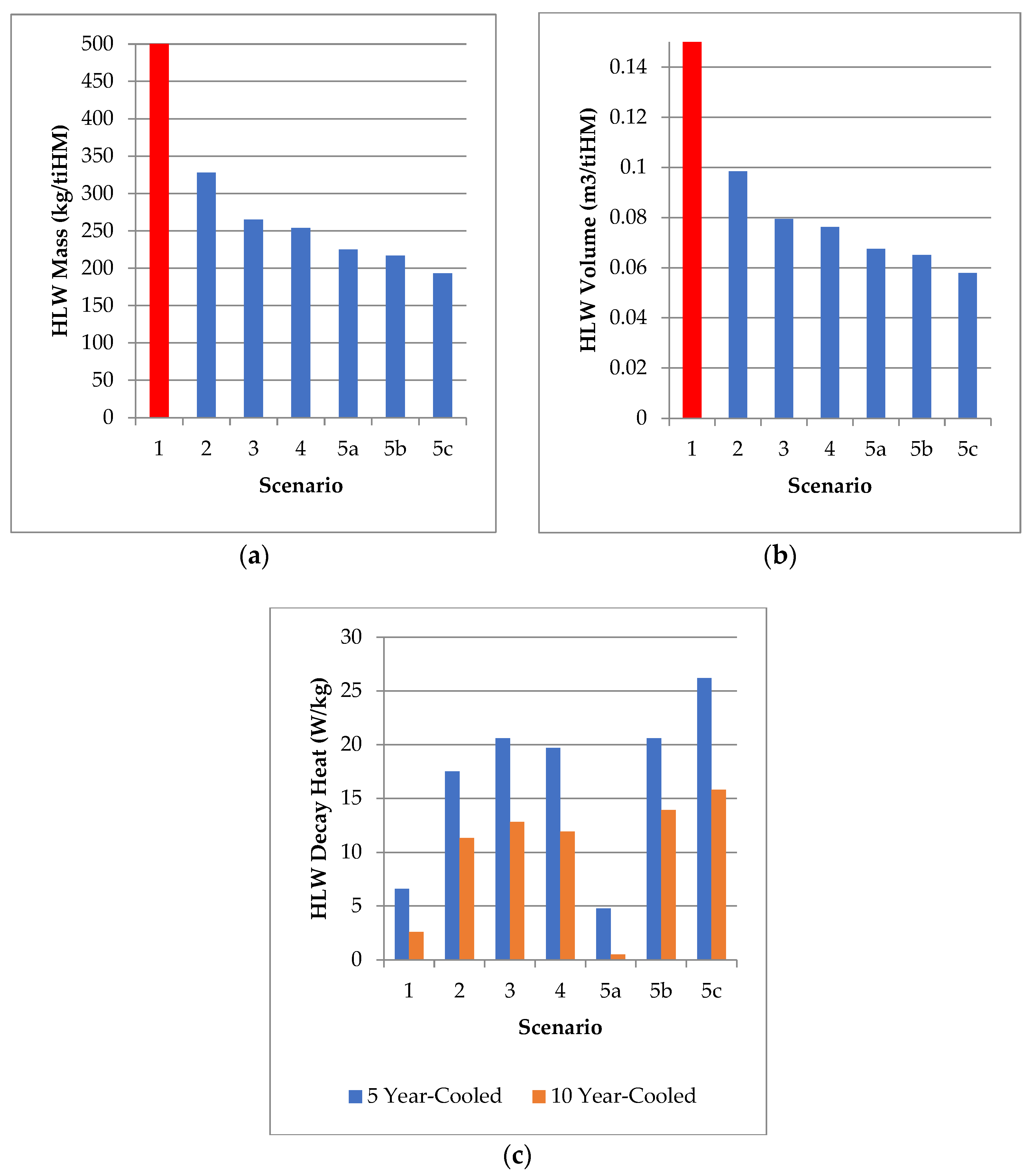
| Scenario | SNF+HLW Mass (t/GWe.y) a | Mass (kg/tiHM) | Volume (m3/tiHM) | Dec. Heat (W/kg, 5 y) | Dec. Heat (W/kg, 10 y) |
|---|---|---|---|---|---|
| 1 (Open Fuel Cycle) | 21.92 (100%, EG01) | 1446 (100%) | >1.21 | 6.61 | 2.59 |
| 2 (UREX) | - | 328 (22.6%) | 0.0984 | 17.5 | 11.3 |
| 3 (PUREX) | 3.42 (15.6%, EG13) 1.46 (6.7%, EG21) | 264–266 (18.3–18.5%) | 0.0795 | 20.6 | 12.8 |
| 4 (PUREX + SANEX) | 1.34 (6.1%, EG24) | 254 (17.5%) | 0.0762 | 19.7 | 11.9 |
| 5a (PUREX + SANEX + HHR) | - | 225 (15.5%) | 0.0675 | 4.76 | 0.49 |
| 5b (PUREX + SANEX + PGM) | - | 217 (15.0%) | 0.0651 | 20.6 | 13.9 |
| 5c (PUREX + SANEX + REE) | - | 193 (13.2%) | 0.0579 | 26.2 | 15.8 |
| Element/Form | Value (USD/kg) | Element Mass (g/tHM) | Activity (Bq/tHM) | Recovered Value (USD/tHM) |
|---|---|---|---|---|
| Ru (Ru) | 20,094 | 4050 | 3.25 × 10¹³ | 81,381 |
| Rh (Rh) | 172,810 | 719 | 3.29 × 10¹³ | 124,250 |
| Pd (Pd) | 29,868 | 2720 | 7.83 × 10⁹ | 81,241 |
| Ag (Ag) | 1065 | 149 | 1.63 × 10¹⁰ | 157 |
| Y (Y2O3) | 6.19 | 816 | 6.36 × 10⁻³ a | 4 |
| La (La2O3) | 0.55 | 2170 | 3.88 × 101 | 1 |
| Pr (Pr2O3) | 52.30 | 1970 | 0 b | ~80 |
| Nd (Nd2O3) | 51.69 | 7280 | 9.95 × 101 | ~300 |
| Gd (Gd2O3) | 19.66 | 259 | 8.55 × 10⁷ | 4 |
| Heavier Ln (M2O3, Tb, Dy, Ho, Er, Tm, Yb) | Various | 7 | 2.86 × 10⁸ | <1 |
Disclaimer/Publisher’s Note: The statements, opinions and data contained in all publications are solely those of the individual author(s) and contributor(s) and not of MDPI and/or the editor(s). MDPI and/or the editor(s) disclaim responsibility for any injury to people or property resulting from any ideas, methods, instructions or products referred to in the content. |
© 2025 by the authors. Licensee MDPI, Basel, Switzerland. This article is an open access article distributed under the terms and conditions of the Creative Commons Attribution (CC BY) license (https://creativecommons.org/licenses/by/4.0/).
Share and Cite
Holdsworth, A.F.; Ireland, E.; Eccles, H. Spent Nuclear Fuel—Waste to Resource, Part 1: Effects of Post-Reactor Cooling Time and Novel Partitioning Strategies in Advanced Reprocessing on Highly Active Waste Volumes in Gen III(+) UOx Fuel Systems. J. Nucl. Eng. 2025, 6, 29. https://doi.org/10.3390/jne6030029
Holdsworth AF, Ireland E, Eccles H. Spent Nuclear Fuel—Waste to Resource, Part 1: Effects of Post-Reactor Cooling Time and Novel Partitioning Strategies in Advanced Reprocessing on Highly Active Waste Volumes in Gen III(+) UOx Fuel Systems. Journal of Nuclear Engineering. 2025; 6(3):29. https://doi.org/10.3390/jne6030029
Chicago/Turabian StyleHoldsworth, Alistair F., Edmund Ireland, and Harry Eccles. 2025. "Spent Nuclear Fuel—Waste to Resource, Part 1: Effects of Post-Reactor Cooling Time and Novel Partitioning Strategies in Advanced Reprocessing on Highly Active Waste Volumes in Gen III(+) UOx Fuel Systems" Journal of Nuclear Engineering 6, no. 3: 29. https://doi.org/10.3390/jne6030029
APA StyleHoldsworth, A. F., Ireland, E., & Eccles, H. (2025). Spent Nuclear Fuel—Waste to Resource, Part 1: Effects of Post-Reactor Cooling Time and Novel Partitioning Strategies in Advanced Reprocessing on Highly Active Waste Volumes in Gen III(+) UOx Fuel Systems. Journal of Nuclear Engineering, 6(3), 29. https://doi.org/10.3390/jne6030029