Review

Review: Pipeline Layout Effect on the Wall Thinning of Mihama Nuclear Power Plants

by
Nobuyuki Fujisawa
1,2
1
Faculty of Engineering, Shinshu University, Nagano 380-8553, Japan
2
Niigata University, Niigata 950-2181, Japan
J. Nucl. Eng. 2025, 6(2), 19; https://doi.org/10.3390/jne6020019
Submission received: 30 April 2025 / Revised: 12 June 2025 / Accepted: 13 June 2025 / Published: 18 June 2025

Abstract

:
The subject of the effect of pipeline layout on wall thinning in Mihama nuclear power plants was reviewed in relation to flow-accelerated corrosion (FAC). The pipeline consists of a complex layout with a straight pipe, elbow, curved pipe, orifice, and T-junction. To understand the mechanism of wall thinning in the pipeline, the basics of FAC, experimental and numerical approaches, and flow and mass transfer studies of the pipeline were reviewed and compared with actual Mihama pipeline data. The results indicate that the wall thinning in the Mihama pipeline was caused by the asymmetric mass transfer phenomenon arising from the pipeline layout effect induced by the swirl flow, resulting in the generation of a spiral flow downstream of the elbow and an increased mass transfer coefficient downstream of the orifice. Swirl flow can be generated by the coupled T-junction and elbow in the upstream pipeline. Furthermore, related topics in flow and mass transfer studies on short elbows and dual and triple elbows were reviewed in relation to wall thinning, which could depend on the elbow curvature, Reynolds number, and surface roughness. The low-frequency flow oscillation in a short elbow, the swirl flow generation in dual and triple elbows, and the influence of wall roughness could be other sources of the increased mass transfer coefficient in the pipeline.

1. Introduction

Flow-accelerated corrosion (FAC) is a critical issue in nuclear energy science and technology because it can limit the lifetime of a pipeline. When FAC occurs in a pipeline, the wall thickness decreases because of the turbulent diffusion of the carbon steel pipe into the bulk flow through the oxide layer of the pipeline. FAC is influenced by the flow velocity, temperature, turbulence, wall shear stress, pH, and dissolved oxygen and hydrogen concentrations in the bulk flow as well as the chromium concentration in the carbon steel. It is highly governed by the mass transfer arising from the concentration gradient of the flow through the pipeline. FAC is a mass transfer phenomenon related to the water chemistry of the pipe material, and such chemistry issues have been reported in several articles [1,2,3,4,5,6].
Pipe wall thinning in nuclear plant pipelines is mostly caused by FAC when the pipeline material is carbon steel [7,8,9]. Past studies on FAC have indicated that the pipe wall thickness can decrease significantly because of flow downstream of the orifice [10,11,12,13,14,15,16,17,18,19,20] and through elbows and curved pipes [21,22,23,24,25,26], compared with that of a straight pipe. These experimental results indicate that pipeline corrosion is a mass transfer phenomenon [27,28,29,30,31,32,33,34,35,36] that is significantly accelerated in a highly turbulent flow when the flow passes through the orifice, elbow, and curved pipe.
The pipe rupture that occurred at the Mihama nuclear power plant in 2004 is a well-known accident caused by FAC [37]; however, it was characterized by asymmetric pipeline layout effect, which was difficult to explain from the FAC phenomenon occurring in an isolated orifice element in an axisymmetric straight pipe. The Mihama pipeline was filled with vapor at a high temperature of 413 K and connected to a complex pipeline geometry consisting of straight pipes, elbows, curved pipes, orifices, and a T-junction, as illustrated in Figure 1. Pipe rupture caused by wall thinning occurred in pipeline A (Figure 1), which was positioned immediately downstream from the orifice. The cross-sectional view showed asymmetric wall thinning in pipeline A. On the contrary, pipeline B consisted of several pipeline elements, similar to those of pipeline A, but asymmetric wall thinning was not observed in pipeline B. A scale model experiment revealed a highly swirling flow in pipeline A, while it was not observed in pipeline B [37]. Therefore, the asymmetric wall thinning in pipeline A could be caused by the mutual interaction of the pipeline elements through the occurrence of swirl flow before the flow enters the elbow and orifice. These preliminary studies on the behavior of the flow in a scaled model showed a rough image of the flow behavior through the Mihama pipeline layout, whereas the physics behind the high wall thinning at the top and low wall thinning at the bottom of pipeline A was not clearly understood [37]. This may be attributable to the difficulty of measuring the entire velocity field and mass transfer distribution in the Mihama pipeline model.
To understand the mechanism of asymmetric wall thinning in the Mihama pipeline, the mutual interaction of pipeline elements, such as the elbow, curved pipe, orifice, and T-junction, was studied by examining the flow and mass transfer behaviors of the Mihama pipeline model [32,33,36]. This was because of the difficulty in explaining the asymmetric wall thinning downstream of an orifice in the Mihama pipeline. When asymmetric wall thinning occurred in the pipeline, the FAC rate on one side of the pipe reached an approximately five-times-larger thinning rate than that on the other side, resulting in a much shorter pipeline lifetime [37]. To understand the mechanism, the influence of spiral flow on the mass transfer behavior of the Mihama pipeline was studied experimentally from the perspective of fluid dynamics because the orifice flow was unstable to disturbances in the upstream flow field [38,39,40,41]. Subsequently, the flow and mass transfer behaviors of the mutual interaction effect of the elbow and orifice under the influence of swirl flow were studied experimentally and numerically [32,33,36,42,43,44]. Furthermore, the flow field variation of a spiral flow downstream of the elbow and orifice in a complex pipeline layout as a result of mutual interaction was investigated under the influence of swirl flow [45,46,47]. The generation of swirl flow by the mutual interaction of the T-junction and elbow was also examined using numerical simulations [48].
The purpose of this review is to study the mechanism of the pipeline layout effect of the Mihama nuclear power plant on the flow and wall thinning, which is characterized by the mutual interaction of the pipeline elements. To understand the mechanism, the flow and mass transfer behaviors of the coupled pipeline elements, such as straight pipes, elbows, curved pipes, orifices, and T-junctions, were investigated. The results were compared with actual observations of asymmetric wall thinning in the Mihama pipeline. Furthermore, recent advances in the generation of swirl flow and flow and mass transfer studies of short elbows, dual and triple elbows, and the influence of wall roughness were reviewed to understand the increased mass transfer coefficient in the elbow depending on the Reynolds number. This could be an important topic in safety management of nuclear pipelines, as recommended in the guidelines [49,50] and inspection methods [51].

2. Basics of Flow-Accelerated Corrosion

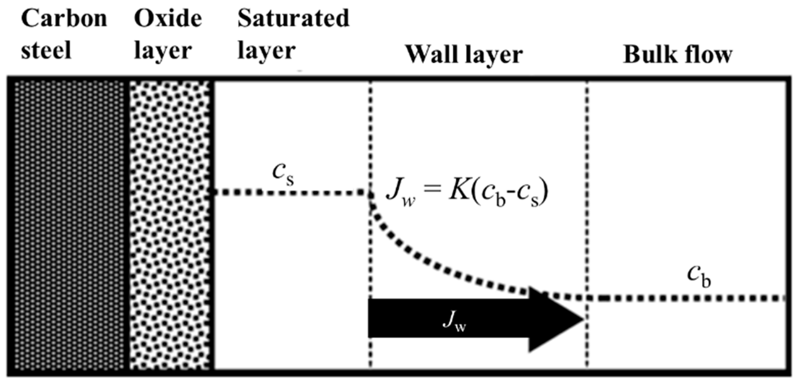
Carbon steel pipelines in nuclear and fossil power plants suffer from degradation of the wall material caused by the electrochemical dissolution of carbon steel into the bulk water flow. This is the basic principle of the degradation mechanism of plant pipelines by FAC. It is well known that the FAC rate depends highly on the temperature, as shown in Figure 2 [3]. The FAC rate increases with increasing temperature with a peak at 400–450 K, and it decreases with further increases in temperature [3,52]. Therefore, the reaction process of carbon steel in the pipeline can be modeled as shown in Figure 3. The oxide layer on the carbon steel dissolves into the water in the form of Fe2+, which diffuses through the wall layer of the flow to the bulk water flow and reacts with OH to generate Fe(OH)2. This results in the formation of Fe2O3 in the flow by the Schikorr reaction.
This reaction process of FAC in the pipeline can be considered a mass transfer phenomenon, which is the turbulent diffusion of Fe2+ in the oxide layer into the flowing water. Therefore, the wall mass flux Jw can be expressed by the concentration gradient of Fe2+ in the wall layer, which is approximately equal to the difference between the saturated concentration cs and the bulk flow cb multiplied by the mass transfer coefficient K [53].
Jw = K (cscb)
Equation (1) does not include the flow parameters, such as the turbulent energy k and wall shear stress τw, which are obtained from the fluid dynamic equations of the flow.

3. Experimental and Numerical Approach to Mihama Pipeline Model

3.1. Experimental Model of Mihama Pipeline and Method

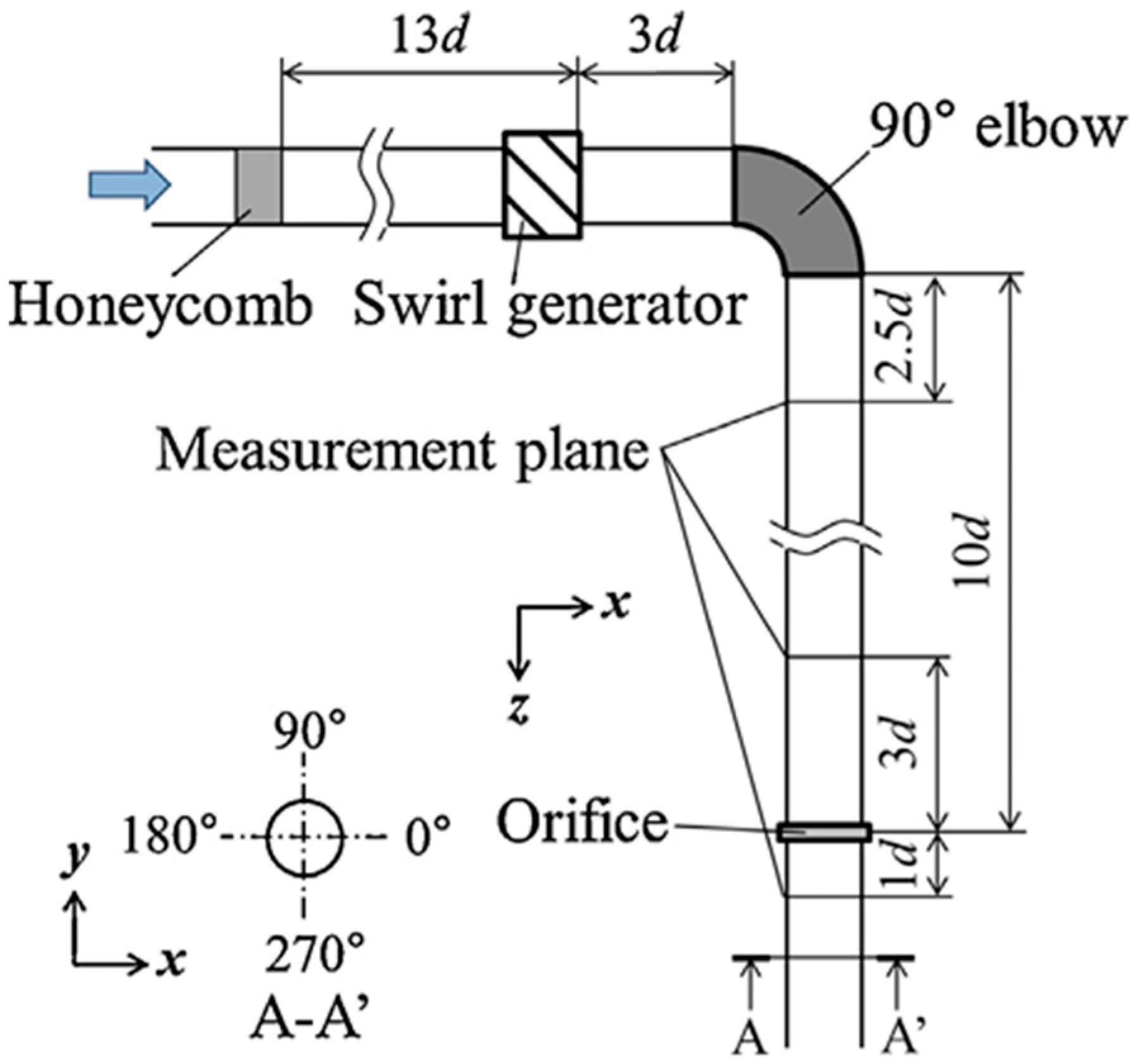
To understand the mechanism of asymmetric wall thinning in the Mihama pipeline, the flow and mass transfer coefficients of the pipeline were measured using a scaled model in a water circuit. Figure 4 shows the scale model of the Mihama pipeline, which consists of a swirl generator, an elbow, a straight pipe, and an orifice. The radius of the elbow curvature is r/d = 1.2, where d is the pipe diameter and r is the radius of elbow curvature. To reproduce the swirl flow upstream of the elbow in Mihama pipeline A (Figure 1) [37], a swirl flow was generated using a swirl generator consisting of several inclined blades [36]. The diameter of the pipe was d = 56 mm and the Reynolds number was Re (=Ud/ν) = 3 × 10⁴, where U is the mean velocity and ν is the kinematic viscosity of the fluid. Note that the Reynolds number Re = 5.8 × 10⁶ of the actual Mihama pipeline was 2 orders higher than that of the pipeline model. The test section was made of transparent material to measure the velocity field using the stereo particle image velocimetry (PIV) system [54,55]. The flow visualization was performed using nylon tracer particles of 40 μm in diameter having a specific gravity of 1.02.
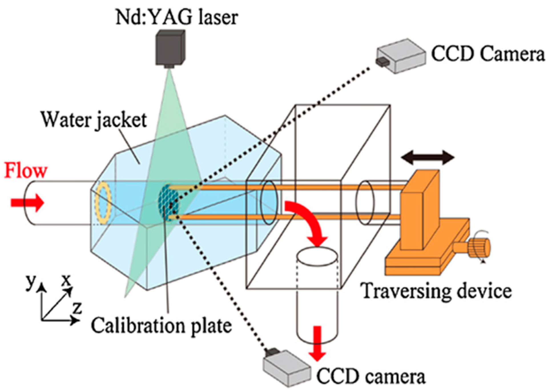
Figure 5 shows the stereo PIV system to measure the three-dimensional velocity field in the cross section of the pipe. The observation was made by two charge-coupled device (CCD) cameras (1018 × 1008 pixels with 8 bits in gray level), double-pulsed Nd:YAG lasers (maximum output power of 70 mJ/pulse), and a pulse controller, through the water jacket. The captured images were processed using an in-house PIV software for the measurement of three-velocity components in a planar section [54]. This technique was applied to the measurement of swirl intensity upstream of the orifice at −3d. The results revealed the formation of a swirl flow with an intensity of S = 0.27, which was approximately equal to that of S = 0.3 in the scale model of the Mihama pipeline [37]. The swirl intensity is defined by the following equation.
S = 0 R u x u θ r 2 d r / ( R 0 R u x 2 r d r )
where R is the pipe radius, r is the radial distance from the pipe center, ux is the axial velocity, and uθ is the circumferential velocity. Furthermore, the planar cross-sectional velocity field downstream of the orifice (x/d = 1) was measured using stereo PIV to understand the influence of the swirl flow on the flow field and mass transfer distribution downstream of the orifice.
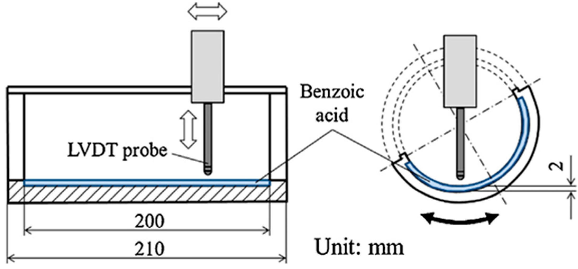
The mass transfer measurement was performed using the test section, as illustrated in Figure 6. Molten benzoic acid was cast into the test section to measure the wall displacement before and after the water flow experiment using a linear variable differential transformer (LVDT) probe. The mass transfer coefficient K was estimated from the measurement of wall-thinning rate δh/δt of benzoic acid in a unit time, obtained from the depth measurements before and after the experiment:
K = ρδh/δt/(cscb)
where ρ is the density of benzoic acid, cw is the wall concentration of benzoic acid, and cb is the concentration of benzoic acid in bulk flow.
The experiment was carried out at the Schmidt number Sc (=ν/D) = 300 at a water temperature of 323 K, where D is the diffusion coefficient of benzoic acid, and ν is the viscosity of fluid [36].

3.2. Numerical Prediction of Wall Thinning in Mihama Pipeline Model

The flow field and mass transfer coefficient downstream of the Mihama pipeline model with elbow and orifice in a swirl flow was numerically studied using the incompressible form of the Reynolds-averaged Navier–Stokes equations of mass, momentum, and concentration. The numerical simulation was made at high Reynolds number turbulent flows coupled with the k-ε model of turbulence [53]. The equations for mass, momentum, and concentration are
u i ¯ x i = 0
u j ¯ u i ¯ x j = 1 ρ p ¯ x i + 1 ρ x j μ u i ¯ x j ρ u i u j ¯
u j ¯ c ¯ x j = x j D c ¯ x j u j c ¯
where u is the velocity, p is the pressure, c is the concentration, ρ is the density, μ is the viscosity, D is the diffusion coefficient, the prime symbol denotes the fluctuation, and the overbar represents time averaging. The Reynolds stress terms in Equation (5) are approximated by the eddy viscosity concept with the turbulent energy k and dissipation rate ε.
u i u j ¯ = ν t u i ¯ x j + u j ¯ x i 2 3 k δ i j
where the eddy viscosity νt is given by
ν t = C μ k 2 ε
with the empirical constant Cμ = 0.09. The turbulent diffusion term in Equation (6) is expressed by the eddy diffusivity of the concentration with the turbulent Schmidt number Sct:
u j c ¯ = ν t S c t c ¯ x j
The turbulent diffusion term in Equation (9) is modeled using the eddy diffusivity with a constant turbulent Schmidt number of 0.9. Equations (4)–(9) were solved using the pressure implicit with the splitting of operators method [56] using OpenFOAM software. Further details of the numerical simulation can be found in the literature [44,53,57,58].
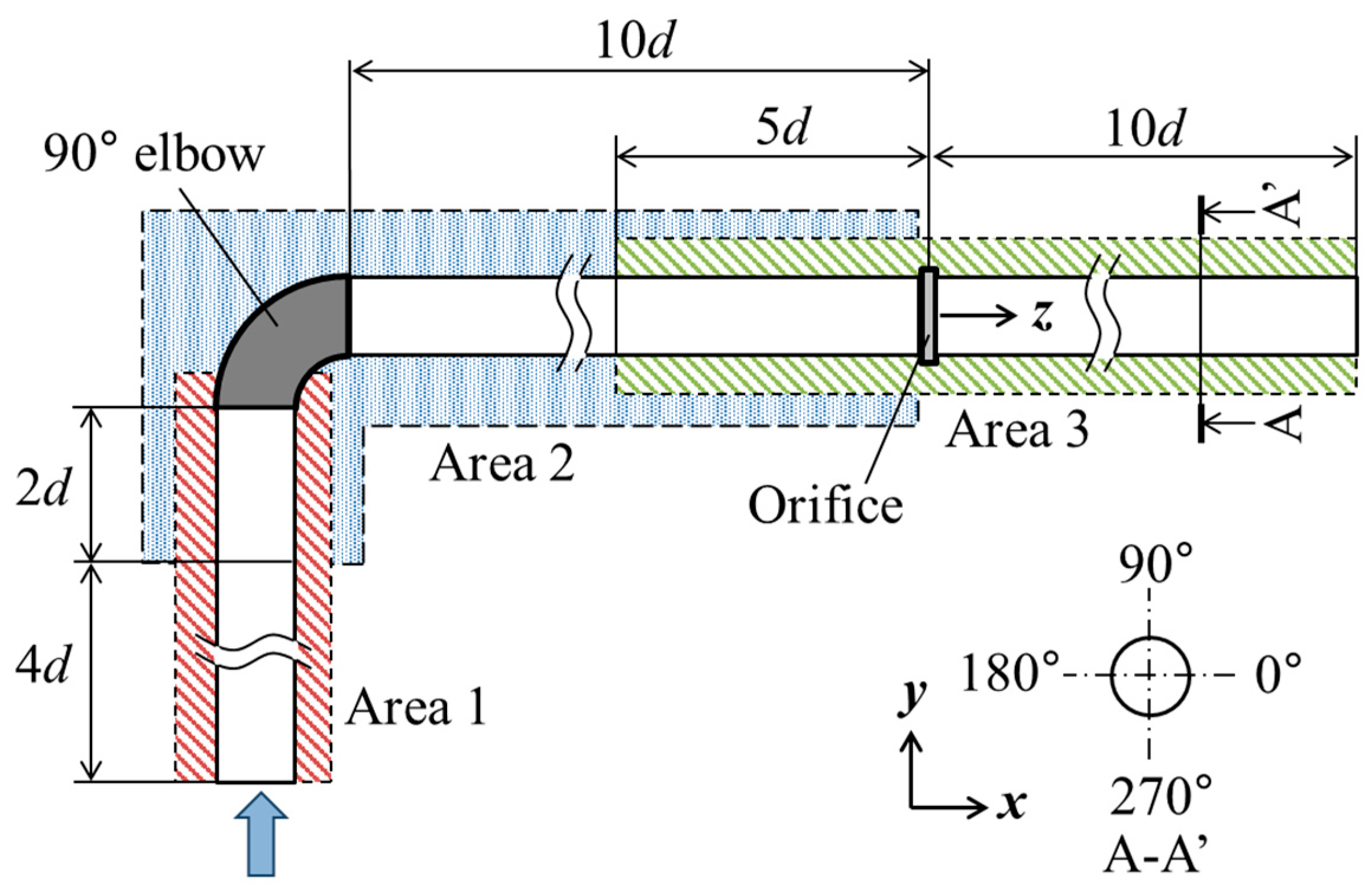
Figure 7 shows the Mihama pipeline model used for the numerical simulation [44]. To compute the flow and mass transfer characteristics in the Mihama pipeline model, the target pipeline was separated into three regions: the inlet section of the swirl flow (Area 1), the flow through the elbow and straight pipe section downstream (Area 2), and the flow downstream of the orifice (Area 3). In reference to the actual plant data of the Mihama pipeline [37], the mean velocity was set to U = 2.2 m/s, and the temperature of the flow was maintained at T = 413 K, which corresponds to a Reynolds number of Re (=Ud/ν) = 5.8 × 10⁶, where d is the pipe diameter (d = 539 mm). The upstream boundary conditions in Area 1 were given by the forced vortex flow to generate the swirl flow with intensity S at −3d upstream of the orifice. The inlet boundary conditions for Areas 2 and 3 were determined from the upstream computational results for Area 1. The outlet boundary conditions were set using zero-gradient conditions for all variables. The near-wall boundary conditions were given by the logarithmic law of the wall [44,53,59].
The wall thinning of the pipe per unit time was estimated using an analogy between the mass and momentum transfer near the wall boundary.
δh/δt = ((cscb)K)/ρ
where cs and cb represent the saturated and bulk-flow concentrations, respectively. Equation (10) shows that the wall-thinning rate δh/δt can be obtained from the concentration gradient multiplied by the estimated mass transfer coefficient K.

4. Experimental and Numerical Results for Mihama Pipeline Model

4.1. Flow Field Measurements and Numerical Simulations

Figure 8a shows the cross-sectional velocity contours measured by stereo PIV in a swirl flow of the Mihama pipeline model downstream of an orifice at x = 1d with S = 0.27 at Re = 3 × 10⁴. The results indicated an asymmetric velocity distribution with a high axial velocity near the top left of the pipe and a high circumferential velocity along the left wall of the pipe, whereas the velocity magnitude on the right side of the pipe remained small. Therefore, the flow downstream of the orifice coupled with the elbow was highly skewed by the influence of the swirl flow. In contrast, the flow downstream of the orifice without the swirl flow maintained an axisymmetric velocity contour with a high velocity at the center and a low velocity near the pipe wall, as shown in Figure 8b. This result indicates the formation of an axisymmetric flow downstream of the orifice, even if the elbow was attached upstream of the orifice and the orifice bias was kept small [39]. Thus, the asymmetric flow downstream of the orifice in Figure 8a can be induced in the Mihama pipeline model when the swirl intensity S of the flow exceeds approximately 0.3.
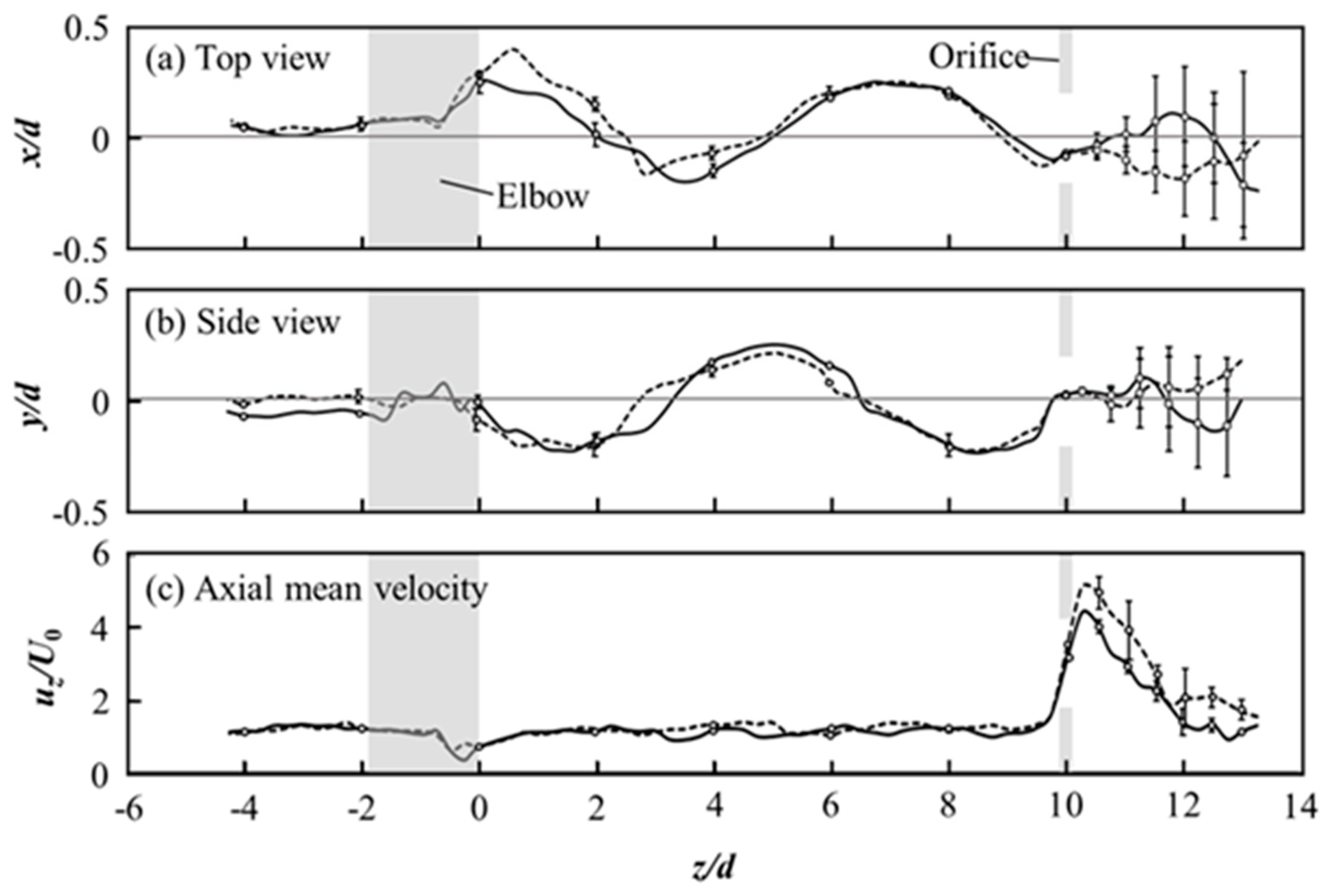
To understand the entire flow field in the Mihama pipeline model, a flow visualization study of the swirl flow in the pipeline was conducted using a transparent pipeline model with a diameter of 56 mm [47]. The experiment was performed using a bubble tracer method in water flow at Re = 3 × 10⁴, where the bubble tracers were successively supplied from an injection tube. The bubble images were captured using two digital cameras situated at a right angle through the water jacket. Note that the velocity measurement was conducted using an in-house PIV software and the bubble center was evaluated using image analysis. Further details of the experimental method are described in Ref. [47]. The bubble flow was observed using two CCD cameras, which made it possible to measure the three-dimensional positions of the bubbles and the axial velocity distribution in the Mihama pipeline model with the elbow and orifice with the aid of image analysis. Measurements were performed for bubbles with diameters of 2 and 3 mm, respectively.
The flow visualization results are summarized in Figure 9, which shows the top view (a), side view (b), and axial velocity variation (c) of the flow. The injected bubbles showed a spiral motion downstream of the orifice with 1.5 cycles in a straight pipe of length 10d, while the axial velocity was approximately constant at 1.2 times the mean velocity up to the position of the orifice. The flow visualization results of the different bubble sizes agreed closely with each other up to the orifice, whereas the flow visualization results indicated a large error and uncertainty in the bubble positions downstream of the orifice. This discrepancy may be attributable to the highly turbulent flow downstream from the orifice. Nevertheless, these results agree within the measurement error range. The axial mean velocity suddenly increased downstream of the orifice by up to 4.5 times the bulk velocity, as shown in Figure 9c, which was followed by a gradual decrease downstream. The position of the maximum axial velocity was 0.5d downstream of the orifice, in rough agreement with the pipe rupture position 1d of the actual Mihama pipeline [37].
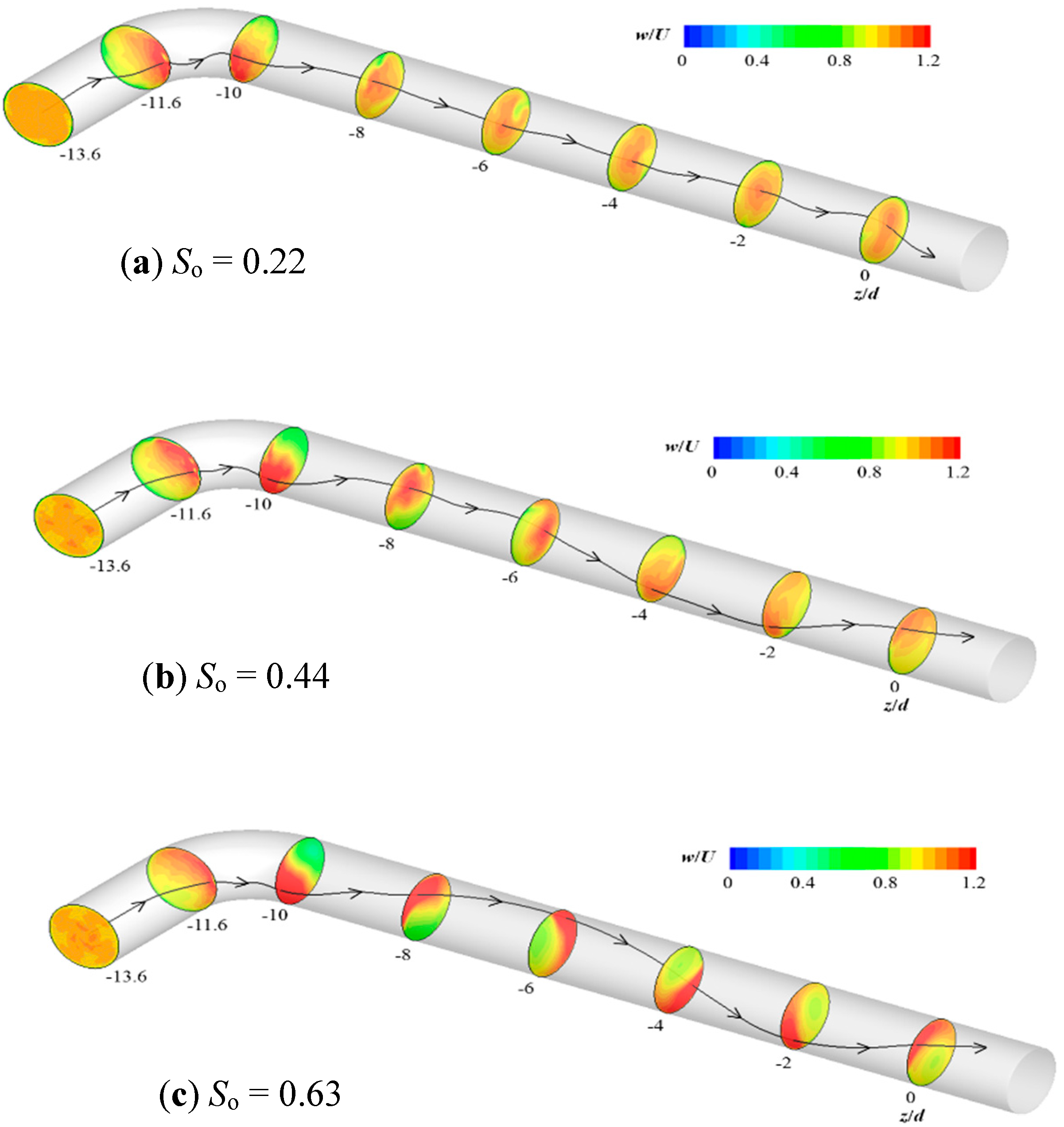
The numerical simulations of flow and mass transfer characteristics were performed using the Reynolds-averaged Navier–Stokes equations of mass, momentum, and concentration coupled with the k-ε model of turbulence at a Reynolds number of Re = 5.8 × 10⁶ [44]. The numerical results obtained from the OpenFOAM software are shown in Figure 10 for the three swirl intensities So defined at −3d upstream of the elbow: So = 0.22, 0.44, and 0.63, where So = 0.44 corresponds to the swirl intensity S = 0.27 at −3d upstream of the orifice in the Mihama pipeline.
When the swirl intensity is low (So = 0.22), the swirl flow through the elbow maintains a non-swirling behavior downstream of the orifice, as shown in Figure 10a. However, the flow through the elbow indicates a spiral flow in the straight pipe downstream of the elbow when the swirl intensity increases to So = 0.44, as shown in Figure 10b. This spiral flow can be generated by the secondary flow in the elbow in a swirl flow, which is induced by the centrifugal instability of the flow through the curved pipe. The secondary flow is generated in the cross section of the elbow, directed from the inner to the outer wall, followed by the return flow along the pipe wall. This results in the formation of a high-velocity region on the inner wall of the elbow that circulates in a spiral flow along the pipe downstream. When the swirl intensity is increased further to So = 0.63, as shown in Figure 10c, the spiral flow is more clearly observed in the pipe downstream of the elbow. The position of the highest mass transfer coefficient downstream of the orifice may be determined by the wavelength of the spiral flow. Therefore, the pipe length between the elbow and orifice is an important factor in determining the circumferential position of the highest mass transfer rate, which can be the position of pipe rupture. Thus, the formation of a spiral flow downstream of the elbow in the Mihama pipeline model was reproduced well in the numerical simulations.

4.2. Mass Transfer and Wall-Thinning Distributions Downstream in Mihama Pipeline Model

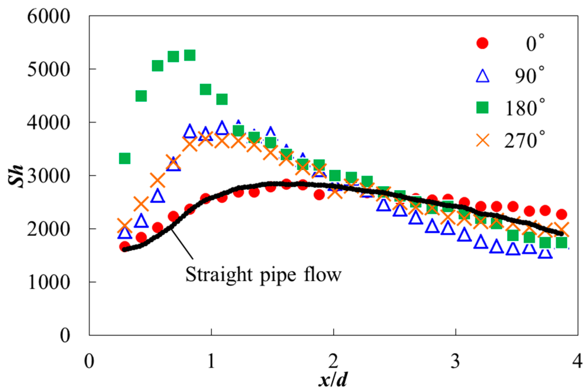
To understand the wall-thinning behavior downstream in the Mihama pipeline model, the Sherwood number distributions were measured in the water flow at T = 293 K using the benzoic acid method combined with a LVDT probe, and the results are shown in Figure 11. The Sherwood number Sh (=Kd/D) is the nondimensional mass transfer coefficient K with diffusion coefficient D and pipe diameter d. The results show that a high mass transfer occurred on the left side of the pipe (180°) and a low mass transfer occurred on the right side (0°), which is approximately the same magnitude as the result for the straight pipe. Thus, the mass transfer distribution downstream of the orifice coupled with the elbow became asymmetric because of the occurrence of a spiral flow downstream of the elbow. The maximum Sherwood number increased from Sh = 2800 at x/d = 1.5 in the straight pipe to Sh = 5400 at x/d = 0.8 in the Mihama pipeline model at Re = 3 × 10⁴. These results indicate that the mass transfer coefficient became almost twice as high downstream of the orifice in the Mihama pipeline model as in the straight pipe. Furthermore, the axial position of the maximum Sherwood number coincided with the actual pipe rupture position at x/d = 1 in the Mihama pipeline [37]. Thus, the pipe rupture mechanism in the Mihama pipeline could have been determined by the spiral flow behavior downstream of the elbow.
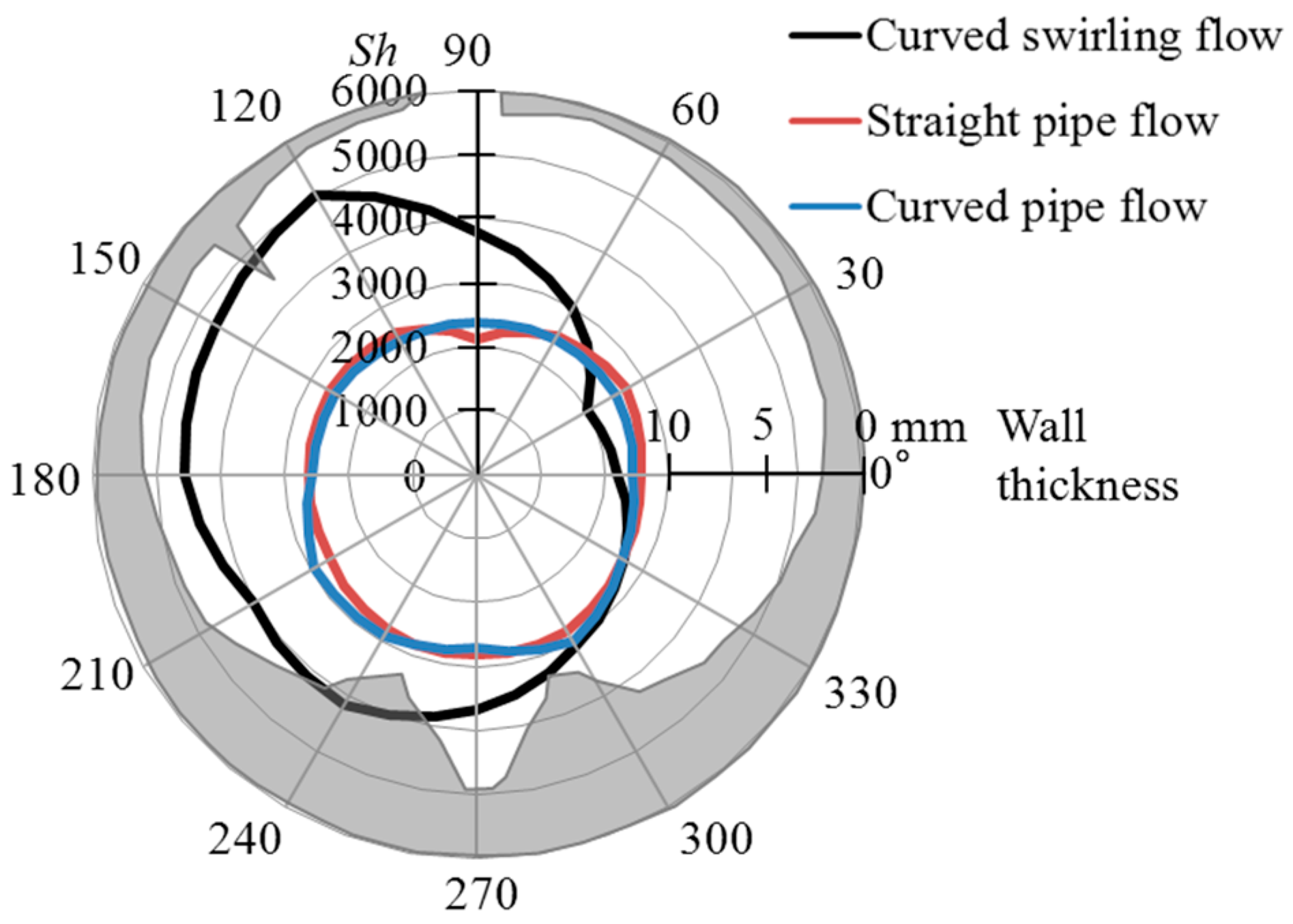
To investigate the mass transfer characteristics downstream of the orifice further, the cross-sectional distribution of the Sherwood number was compared with the actual pipe-wall thickness distribution of the Mihama pipeline data shown in Figure 12. The measurements were performed using the benzoic acid method combined with a LVDT probe. The experimental results indicate that the maximum Sherwood number distribution occurred on the top left side of the pipe wall and the minimum appeared on the right side of the pipe wall. The pipe wall thickness distribution of the actual Mihama pipeline downstream of the orifice at x/d = 1 [37] was nearly reproduced in the experimental results at Re = 3 × 10⁴. The Sherwood number distribution without swirl flow is shown in Figure 12 for comparison, and it agrees closely with the results of the straight pipe. These results indicate that the Sherwood number distribution became asymmetric downstream of the orifice and that the magnitude increased because of the swirl flow caused by the coupled effect of the elbow and orifice in the Mihama pipeline model.
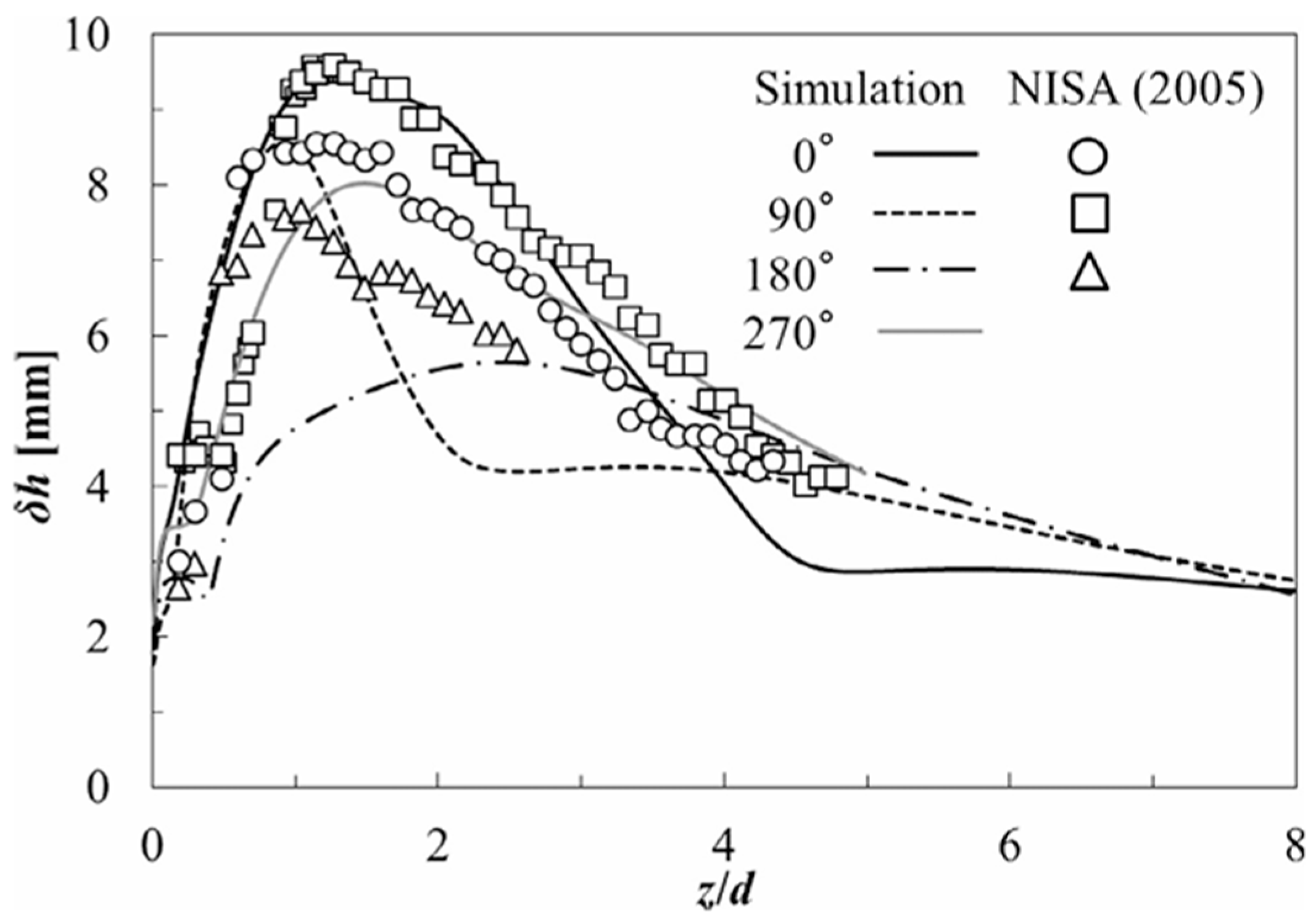
Figure 13 shows the axial variations of the wall-thinning distribution downstream of the orifice, comparing the numerical results obtained from the OpenFOAM software with the actual Mihama pipeline data [37]. The wall thinning δh was evaluated from Equation (9) at a water temperature of 413 K, pH of 9.1, and Re = 5.8 × 10⁶ in the numerical simulation. The wall-thinning distributions are shown at four typical circumferential positions, θ = 0°, 90°, 180°, and 270° (see Figure 4), at the same Reynolds number. The wall-thinning distributions were highly biased toward the upper-right side of the pipe. Although there were minor differences between the maximum wall thinning at angle at θ = 0° in the prediction and the actual Mihama pipeline data at θ = 0°, they occurred at the same axial position x/d = 1–1.5, indicating the agreement between the prediction and the actual plant data. In contrast, lower wall thinning was predicted on the lower side of the pipe, resulting in a wall-thinning distribution downstream of the orifice that was asymmetric. The actual pipe wall thickness was not measured around θ = 270°.

4.3. Numerical Studies on the Generation of Swirl Flow in Coupled T-Junction and Elbow

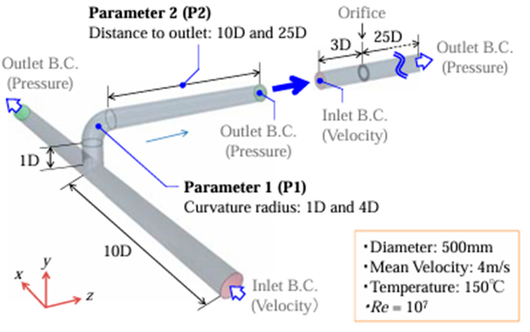
A numerical study was conducted on the generation of swirl flow in a coupled T-junction and elbow, which corresponds to the pipeline geometry in the Mihama pipeline before entering the 90° elbow (Figure 1). To understand the mechanism of swirl flow generation in the coupled T-junction and elbow, Suzuki et al. [60] conducted a numerical study to evaluate the flow and mass transfer coefficient using the Navier–Stokes equations combined with a realizable k-ε two-layer model. The mass transfer coefficient was approximately evaluated using the effective friction velocity with the Chilton–Colburn analogy. The numerical simulation was performed at temperature T = 413 K and Reynolds number Re = 1 × 10⁷ for various combinations of T-junction and elbows [61,62].
Figure 14 shows the numerical pipeline geometry with the coupled T-junction and elbow [48]. The flow computation was performed using STAR-CCM+ code with a realizable k-ε two-layer model of turbulence. Cross-sectional velocity contours downstream of the coupled T-junction and elbow are shown in Figure 15 at Re = 1 × 10⁷, which compares the velocity contours at 10d downstream of the elbow with different radiuses of elbow curvature r = 1d (a) and 4d (b). These results showed the occurrence of swirl flow downstream of the elbow when the distance between the T-junction and the elbow was kept small at 1d independent of the elbow curvature and they are placed in an out-of-plane configuration [48]. The swirl flow occurred downstream of the elbow, and the swirl intensity increased with a decrease in the radius of the elbow curvature r = 4d to 1d. The resulting swirl intensities of the flow through the pipeline were S = 0.11 (r = 4d) and S = 1.1 (r = 1d). Therefore, the results for the short elbow (r/d = 1) satisfied the experimental swirl intensity S > 0.3 of the increased mass transfer coefficient condition [36]. This implies that the generation of a swirl flow downstream of the T-junction combined with an elbow is possible when they are placed in an out-of-plane configuration. Furthermore, the numerical results show that the mass transfer coefficient increased by more than four times that of the straight pipe when the coupled T-junction and elbow were placed at a distance of 1d between the T-junction and short elbow [63]. These numerical results indicate the occurrence of strong swirl flow with an intensity S > 0.3 downstream of the coupled T-junction and elbow in the Mihama pipeline model.
These findings on the flow and mass transfer mechanism of the Mihama pipeline indicate the following guideline for pipeline design. To minimize the wall thinning of the pipeline, it is important to suppress the swirl intensity below 0.3 by decreasing the elbow curvature and increasing the distance between the T-junction and the elbow. The out-of-plane configuration of the T-junction and elbow should be avoided to minimize the swirl flow. Furthermore, attention should be paid to the pipeline layout effect on the wall thinning downstream of the orifice by increasing the distance between elbow and orifice.

5. Recent Advances in Flow and Mass Transfer Studies on Curved Pipes and Elbows

5.1. Flow Field Studies on Curved Pipes and Elbows

Flows through curved pipes and elbows are important topics of interest in nuclear science and technology. However, they are not well understood in the literature, especially at high Reynolds numbers. This may be because of the complex flow phenomenon dependent on the Reynolds number of the flows through the curved pipe and elbow, where the flows suffer from the influence of centrifugal forces and instability. Basic studies on the pressure drop and velocity measurements in curved pipes and elbows were summarized by Spedding et al. [64]. Since then, numerical and experimental studies on the turbulent structure and unsteady flow behavior through curved pipes and elbows have been conducted [65,66,67,68,69,70,71,72,73].
The flow through a short elbow is characterized by the elbow curvature (r/d = 1), where r is the radius of the elbow curvature, and d is the pipe diameter. The flow and unsteady behavior of the short elbow has become a topic of interest in nuclear plant research because it saves plant space in comparison with a long elbow (r/d = 1.5). However, the flow field inside the short elbow is more complex than that inside the long elbow because of the occurrence of flow separation downstream of the elbow, where the flow is unsteady owing to flow instability caused by centrifugal forces. The unsteady flow behavior was evaluated experimentally using high-speed PIV, and the flow separation characteristics in a short elbow were studied at a Reynolds number of Re = 5.4 × 10⁵ [67]. It should be mentioned that the unsteady flow behavior of the short elbow was examined from the perspective of flow-induced vibration using a scale model of the Japan sodium-cooled fast reactor (JSFR) for cold leg piping systems.
To investigate the mechanism of the unsteady flow behavior downstream of the short elbow, a numerical simulation of the flow field was performed using large-eddy simulation [68]. It showed that secondary flow occurred in the separating flow region downstream of the short elbow in the Reynolds number range from Re = 500 to 1.47 × 10⁷, covering laminar to postcritical Reynolds numbers. Furthermore, unsteady flow and pressure fluctuations were measured downstream of the short elbow [68,69,70,71,72,73]. These experimental results support the occurrence of a secondary flow in the separating flow region downstream of a 90° short elbow, and the flow structure was found to depend on the Reynolds number.
The flow through a 90° short elbow at a high Reynolds number is associated with low-frequency oscillation of the flow through the piping system, which is the unsteady behavior of the secondary flow and is called the “swirl switching phenomenon”. This is critical to the design of pipeline systems because the periodic oscillation of the flow downstream of the short elbow may cause flow-induced vibration as well as an increased mass transfer rate downstream of the elbow [74,75,76,77,78,79,80,81]. An example of a cross-sectional velocity contour of turbulent pipe flow downstream from a 90° long elbow is shown in Figure 16 at Re = 3.4 × 10⁴ [76]. The measurements were performed at the plane 0.67d downstream of the elbow using the commercial software DaVis 7.2. The top velocity contours in Figure 16 show an instantaneous snapshot of the velocity field, and the bottom velocity contours represent the reconstructed velocity fields from the first six proper orthogonal decomposition (POD) modes of POD analysis using MATLAB. These velocity contours indicate the presence of clockwise and counterclockwise swirl flows in the pipeline, resulting in periodic oscillation of the flow downstream of the long elbow, whereas similar oscillations were observed downstream of the short elbow [81]. This phenomenon may have contributed to an increase in the mass transfer rate downstream of the short elbow.
Furthermore, several studies on flows through dual and triple elbows have been performed from the perspective of practical application in nuclear piping [82,83,84,85,86]. An example of the flow structure shortly after the second elbow of the dual elbow is shown in Figure 17 at Re = 5 × 10⁴, measured using matched refractive-index PIV with a sodium iodide solution as the working fluid [82]. The PIV analysis was performed using the software Vid-PIV. The formation of a swirl flow downstream of the second elbow was observed when the elbows were placed in an out-of-plane configuration. These experimental findings for dual elbows were also reproduced in a numerical simulation [63], suggesting the presence of swirl flow downstream of the dual and triple elbows in the nuclear plant pipeline.

5.2. Mass Transfer Studies on Curved Pipes and Elbows

Mass transfer measurements on a 90° elbow were first performed by Achenbach [87], who employed the naphthalene sublimation method [88], using an air flow through a long elbow of a pipe with a radius-to-diameter ratio r/d = 1.5. The experiment was performed at Reynolds numbers Re = 4 × 10⁴ and 3.9 × 10⁵ and at Schmidt number Sc = 2.53. Subsequently, further mass transfer measurements were performed in water flows for several pipe radius-to-diameter ratios [89,90,91,92,93,94]. These experimental results showed that the mass transfer coefficient distributions were highly scattered inside the elbow. This is because of not only the influence of the pipe radius-to-diameter ratios but also the influence of the Reynolds numbers, Schmidt numbers, and surface roughness.
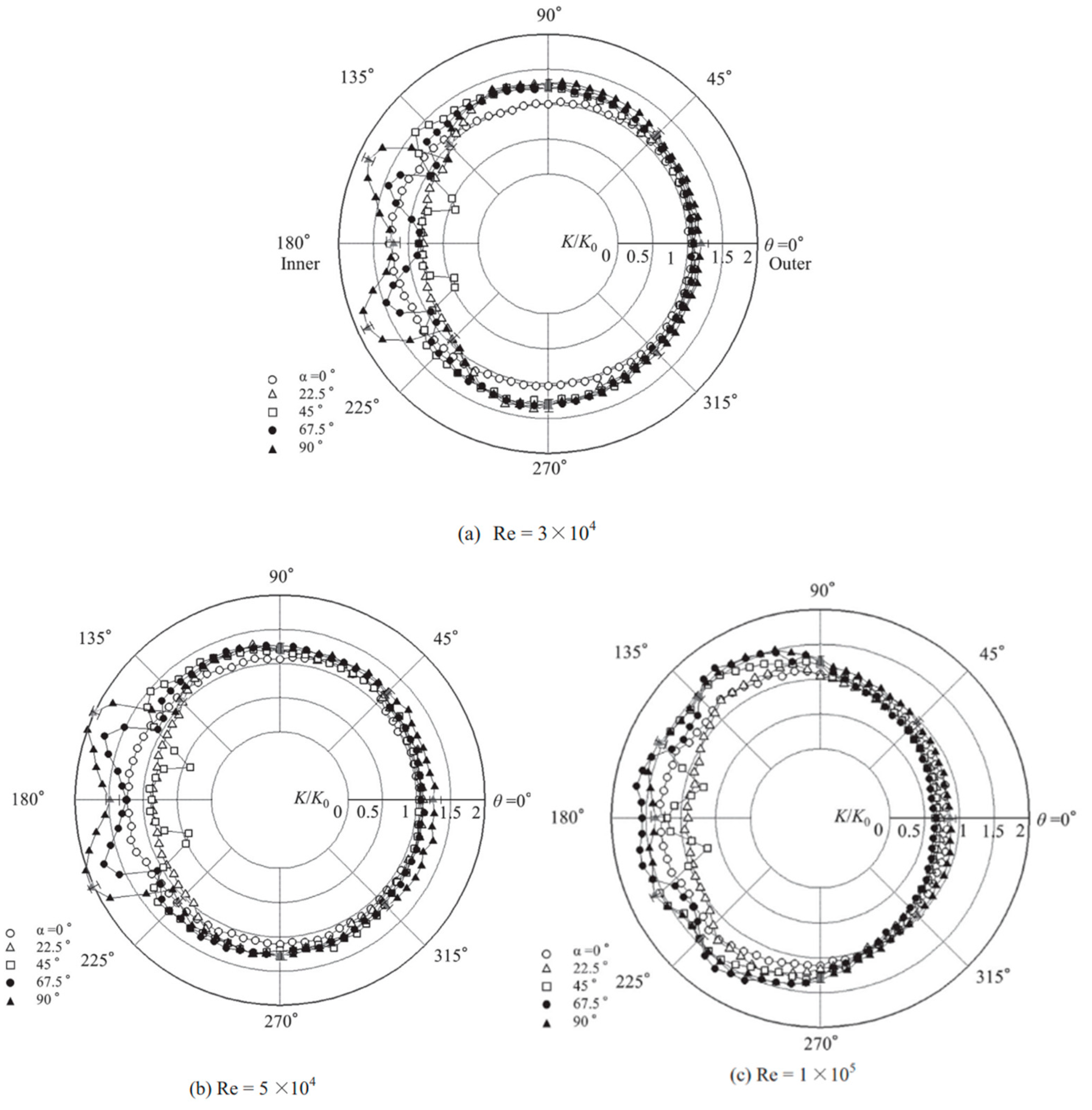
Figure 18a–c show examples of mass transfer distributions on a 90° short elbow with a radius-to-diameter ratio of 1 at Reynolds numbers of 3 × 10⁴, 5 × 10⁴, and 1 × 10⁵, respectively, which were measured using the plaster dissolution method combined with the laser displacement sensor [93]. The mass transfer distribution on the short elbow increased on the inner wall; however, the magnitude of the mass transfer coefficient showed the influence of the Reynolds number, particularly at higher Reynolds numbers. With lower Reynolds numbers of 3 × 10⁴ and 5 × 10⁴, the peak mass transfer coefficient on the inner wall increased by up to 2 times that of the straight pipe at θ = ±25°, whereas it decreased 1.5–1.6 times at a higher Reynolds number of 1 × 10⁵. These results indicate that the mass transfer coefficient increased in the first half of the inner wall of the short elbow; however, the degree of increment was influenced by the Reynolds number. The experimental results show an abrupt decrease in the mass transfer coefficient when the Reynolds number increased beyond 1 × 10⁵ [89,90,91,92,93]. Surface flow visualization of the short elbow showed that the secondary flow was weakened with an increased Reynolds number and that the flow was accelerated in the second half of the elbow, resulting in the weakening of the flow separation at higher Reynolds numbers [81,93,94]. This resulted in a decreased mass transfer coefficient in the second half of the short elbow, reflecting the influence of the Reynolds number.
Mass transfer measurements of the in-plane dual elbows were performed at Re = 7 × 10⁴ and Sc = 1280 [95]. The results indicated that the maximum mass transfer coefficients were found between the outlet of the first elbow and the inlet of the second elbow, and the magnitude increased with decreasing distance between the two elbows. This indicates an increased mass transfer coefficient between the two elbows because of the interaction of the flows through the two elbows.

5.3. Influence of Wall Roughness and Formation of Scallop Pattern

Further studies on the mass transfer characteristics were conducted to determine the influence of wall roughness because an increased mass transfer coefficient was observed on the rough surfaces of the pipeline [96,97,98,99,100,101,102,103,104]. The mass transfer coefficient on the rough wall increased in comparison with the smooth wall, and that on the periodic roughness increased to more than twice that of the smooth pipe. The peak mass transfer coefficient occurred around the flow reattachment point on the rough wall. This was caused by the occurrence of a local recirculating flow region over the periodic roughness, and an increased mass transfer coefficient was observed downstream of the flow reattachment region [101,102,103,104].
The formation of scallop patterns is often observed in the highly corroded region due to the flow-accelerated corrosion of the pipeline [2,4,5,20,21]. The scallop pattern is a three-dimensional roughness, and it plays the role of roughness. The mechanism of scallop formation was caused by the interaction of the flow and the wall [105]. When the pipe wall is soluble, the interaction of the flow and wall leads to the development of three-dimensional structure on the wall. The occurrence of this scallop was investigated theoretically and experimentally [106,107,108,109,110,111], and they showed a range of wavelengths and Reynolds numbers for the occurrence of the scallop pattern, which are closely related to the dissolution rate. It should be mentioned that the scallop pattern was determined not only by the hydraulic parameters, but also by the temperature, pH, and oxygen content. This suggests the complexity of physical and chemical phenomena in the scallop formation. Although the two-dimensional scallop geometry was predicted by numerical simulation considering the mass transfer [112,113], the actual three-dimensional scallop pattern was not predicted yet. Furthermore, the scallop formation was clearly observed on the outer wall of the curved pipe, not on the inner wall, where the higher mass transfer coefficient was expected to occur [114]. Thus, these topics are not clearly understood at present, and they require further study.
Furthermore, the flow and mass transfer phenomenon in the pipeline might be influenced by the Reynolds numbers, which were in the order of 106–107 in the actual nuclear plants, while most of the experimental studies in the literature were conducted at Reynolds numbers in the order of 104–105. It is generally known that the influence of Reynolds number on the flow and mass transfer behavior is considered small, but the influence is not fully understood in the present state of the art. Nevertheless, the present mass transfer data at low Reynolds number flow agree qualitatively with that of the plant data of Mihama at high Reynolds number. This suggests that the mass transfer characteristics of the plant at high Reynolds number can be approximately represented by that of the low Reynolds number flow. Therefore, the influence of the Reynolds number on the flow and mass transfer characteristics of the pipeline elements, along with the roughness effect, are important topics of interest in the future study of pipe wall thinning in nuclear power plants.

6. Conclusions

This review summarized the experimental and numerical studies on the pipe wall thinning in the Mihama nuclear power plant. The pipeline has a complex layout, including straight pipes, elbows, curved pipes, orifices, and T-junctions. The experimental and numerical results on coupled pipeline elements, flows through elbows and curved pipes, dual and triple elbows, and the influence of wall roughness are summarized as follows.
(1)
The rupture of the Mihama pipeline was caused by asymmetric wall thinning down-stream of the orifice owing to the FAC. This was caused by the pipeline layout effect of the mutual interaction of flows through the elbow, orifice, and other pipeline elements in a swirl flow. The orifice flow responded highly to the spiral flow generated by the elbow in the swirl flow, which was the major cause of asymmetric pipe wall thinning downstream of the orifice in the Mihama pipeline model.
(2)
The interaction of the flow through the elbow and orifice in the Mihama pipeline model exhibited an increased mass transfer coefficient downstream of the orifice when the swirl intensity exceeded 0.3. This might have been a cause of the pipe rupture in the Mihama pipeline downstream of the orifice. The position of the pipe rupture might depend on the distance between the elbow and orifice because the spiral flow behavior is closely related to the asymmetric wall thinning downstream of the elbow.
(3)
A numerical simulation revealed the generation of a swirl flow downstream of the elbow when the T-junction flow entered the elbow in an out-of-plane configuration. An increased mass transfer coefficient was observed downstream of the elbow, caused by the interaction of the flow through the T-junction and elbow. This suggests the possible generation of swirl flow at the entry of the Mihama pipeline model. When the elbow curvature and the distance between the T-junction and elbow decreases, the swirl intensity increases beyond 0.3 of an increased mass transfer coefficient condition.
(4)
The flow downstream of the curved pipes and coupled elbows is a critical issue at the high Reynolds number of the actual pipeline. This is because the flow downstream of the short elbow is affected by the secondary flow and flow separation, resulting in low-frequency flow oscillations downstream of the elbow. This flow oscillation could be the cause of the increased mass transfer coefficient in the piping system. When the dual and triple elbows were placed in an out-of-plane configuration, a swirl flow was generated downstream of the elbow. This results in an asymmetric mass transfer coefficient and increased wall thinning downstream of the elbow.
(5)
The mass transfer coefficients in the short elbow exhibited an increase in the first half of the inner wall, whereas it decreased in the second half of the inner wall at high Reynolds numbers. An increased mass transfer coefficient was observed in coupled short elbows when they were located in an out-of-plane configuration. Furthermore, the influence of surface roughness and scalloping on the mass transfer coefficient helped increase the mass transfer coefficient in the pipeline. However, these topics, including the influence of the Reynolds number, are not clearly understood at present and require further study.

Funding

This research received no external funding.

Data Availability Statement

No new data were created or analyzed in this study. Data sharing is not applicable to this article.

Acknowledgments

The author expresses gratitude to F. Inada and S. Watanabe of Central Research Institute of Electric Power Industry and S. Iio and M. Takizawa of Shinshu University for their helpful support during this study.

Conflicts of Interest

The author declares no conflict of interest.

Nomenclature

cconcentration
cbconcentration in bulk flow
cssaturated concentration
Ddiffusion coefficient
dpipe diameter
Jwwall mass flux
Kmass transfer coefficient
kturbulent energy
ppressure
Rpipe radius
rradial distance
ReReynolds number
Sswirl intensity at −3d upstream of orifice
Soswirl intensity at −3d upstream of elbow
ScSchmidt number
ShSherwood number
ttime
Ustreamwise mean velocity
uvelocity
waxial velocity component
x, y, zcoordinates (See Figure 4)
δh/δtwall thinning rate
εdissipation rate
θangle
μviscosity
νkinematic viscosity
ρdensity

References

  1. Dooley, R.B.; Chexal, V.K. Flow-accelerated corrosion of pressure vessels in fossil plants. Int. J. Pres. Ves. Pip. 2000, 77, 85–90. [Google Scholar] [CrossRef]
  2. Dooley, R.B. Flow-accelerated corrosion in fossil and combined cycle/HRSG plants. Power Plant Chem. 2008, 10, 68–89. [Google Scholar]
  3. Fujiwara, K.; Domae, M.; Yoneda, K.; Inada, F.; Ohira, T.; Hisamune, K. Correlation of flow accelerated corrosion rate with iron solubility. Nucl. Eng. Des. 2011, 241, 4482–4486. [Google Scholar] [CrossRef]
  4. Kain, V.; Roychowdhury, S.; Ahmedabadi, P.; Barua, D.K. Flow accelerated corrosion: Experience from examination of components from nuclear power plants. Eng. Fail. Anal. 2011, 18, 2028–2041. [Google Scholar] [CrossRef]
  5. Dooley, B.; Lister, D. Flow-accelerated corrosion in steam generating plants. Power Plant Chem. 2018, 20, 194–244. [Google Scholar]
  6. Khunphakdee, P.; Chalermsinsuwan, B. Review of flow accelerated corrosion mechanism, numerical analysis, and control measures. Chem. Eng. Res. Des. 2023, 199, 519–535. [Google Scholar] [CrossRef]
  7. Keller, H. Erosionskorrosion an nassdampfturbien. VGB-Kraftwerkstechnik 1974, 54, 292–295. [Google Scholar]
  8. Sanchez-Caldera, L.E. The Mechanism of Corrosion Erosion in Steam Extraction Lines of Power Station. Ph.D. Thesis, MIT Department of Mechanical Engineering, Cambridge, MA, USA, 1984. [Google Scholar]
  9. Uchida, S. Latest experience with water chemistry in nuclear power plants in Japan. Power Plants Chem. 2006, 8, 282–292. [Google Scholar]
  10. Yoneda, K.; Morita, R. Investigation of flow characteristics affecting on pipe wall thinning (part 1): Turbulent properties at orifice downstream in single phase flow. CRIEPI Res. Rep. 2006, L05007. (In Japanese) [Google Scholar]
  11. Yoneda, K.; Morita, R.; Satake, M.; Inada, F. Quantitative evaluation of effective factors on flow accelerated corrosion (part 2): Modelling of mass transfer coefficient with hydraulic features at wall. CRIEPI Res. Rep. 2008, L07015. (In Japanese) [Google Scholar]
  12. Uchida, S.; Okada, H.; Naitoh, M.; Uehara, Y.; Koshizuka, S.; Lister, D.H.; Svoboda, R. Effects of water chemistry on flow accelerated corrosion and liquid droplet impingement accelerated corrosion. Power Plant Chem. 2009, 11, 704–717. [Google Scholar]
  13. Hwang, K.M.; Jin, T.E.; Kim, K.H. Identification of relationship between local velocity components and local wall thinning inside carbon steel piping. J. Nucl. Sci. Technol. 2009, 46, 469–478. [Google Scholar] [CrossRef]
  14. Ahmed, W.H. Evaluation of the proximity effect on flow-accelerated corrosion. Ann. Nucl. Ene. 2010, 37, 598–605. [Google Scholar] [CrossRef]
  15. Kim, K.H.; Park, S.H.; Hwang, K.M. Verification of the interrelation between local wall thinning and velocity components observed in the deflected turbulent flow inside orifice of carbon steel piping. Microsyst. Technol. 2010, 16, 1945–1950. [Google Scholar] [CrossRef]
  16. Uchida, S.; Naitoh, M.; Okada, H.; Uehara, Y.; Koshizuka, S. Evaluation of flow accelerated corrosion by coupled analysis of corrosion and flow dynamics: Relationship of oxide film thickness, hematite/magnetite ratio, ECP and wall thinning rate. Nucl. Eng. Des. 2011, 241, 4585–4593. [Google Scholar] [CrossRef]
  17. Pietralik, J.M.; Schefski, C.S. Flow and mass transfer in bends under flow-accelerated corrosion wall thinning conditions. J. Eng. Gas Turbines Power 2011, 133, 012902. [Google Scholar] [CrossRef]
  18. Pietralik, J.M. The role of flow in flow-accelerated corrosion under nuclear power plant conditions. E-J. Adv. Maint. 2012, 4, 63–78. [Google Scholar]
  19. Utanohara, Y.; Nagaya, Y.; Nakamura, A.; Murase, M. Influence of local flow field on flow accelerated corrosion downstream from an orifice. J. Power Ene. Syst. 2012, 6, 18–33. [Google Scholar] [CrossRef]
  20. Kain, V. Flow accelerated corrosion: Forms, mechanisms and case studies. Procedia Eng. 2014, 86, 576–588. [Google Scholar] [CrossRef]
  21. Abe, H.; Watanabe, Y.; Nakashima, M.; Tatsuki, T. Characterization of the corroded surface morphology of a carbon steel piping elbow affected by flow-accelerated corrosion. E.-J. Adv. Mainte. 2017, 9, 26–32. [Google Scholar]
  22. Utanohara, Y.; Murase, M. Influence of flow velocity and temperature on flow accelerated corrosion rate at an elbow pipe. Nucl. Eng. Des. 2019, 342, 20–28. [Google Scholar] [CrossRef]
  23. Madasamy, P.; Chandramohan, P.; Mukunthan, M.; Mohan, T.K.; Rangarajan, S.; Uttam, N.; Nair, J.P. Flow accelerated corrosion rate on carbon steel pipe bend by thin layer activation technique and computational modeling: Under PHWR operating conditions. Eng. Fail. Anal. 2021, 121, 105125. [Google Scholar] [CrossRef]
  24. Bao, G.; Qin, W.; Pan, D.; Si, X. Empirical model of flow-accelerated corrosion at elbow of carbon steel pipeline based on dimensional analysis. Ann. Nucl. Ene. 2024, 201, 110462. [Google Scholar] [CrossRef]
  25. Moon, S.; Lee, J.Y.; Kim, K.M.; Han, S.W.; Lee, G.G.; Maeng, W.Y.; Kim, D.J. Assessment of flow-accelerated corrosion-induced wall thinning in SA106 pipes with elbow sections. Nucl. Eng. Technol. 2024, 56, 1244–1249. [Google Scholar] [CrossRef]
  26. Xu, T.; Zhang, R.; Si, X. Effects of fluid dynamics parameters on flow-accelerated corrosion at elbow of carbon steel pipeline. Mat. Res. Express 2024, 11, 056520. [Google Scholar] [CrossRef]
  27. Sydberger, T.; Lotz, U. Relation between mass transfer and corrosion in a turbulent pipe flow. J. Electrochem. Soc. 1982, 129, 276–283. [Google Scholar] [CrossRef]
  28. Nakamura, A.; Murase, M.; Utanohara, Y.; Nagaya, Y. The effect of local flow field on flow accelerated corrosion: The background of the research and measurements of corrosion rate after an orifice. INSS J. 2008, 15, 78–87. (In Japanese) [Google Scholar]
  29. Ahmed, W.H.; Bello, M.M.; Nakla, M.E.; Sarkhi, A.A. Flow and mass transfer downstream of an orifice under flow accelerated corrosion conditions. Nucl. Eng. Des. 2012, 252, 52–67. [Google Scholar] [CrossRef]
  30. El-Gammal, M.; Ahmed, W.H.; Ching, C.Y. Investigation of wall mass transfer characteristics downstream of an orifice. Nucl. Eng. Des. 2012, 242, 353–360. [Google Scholar] [CrossRef]
  31. Ahmed, W.H.; Bello, M.M.; El Nakla, M.; Al Sarkhi, A.; Badr, H.M. Experimental investigation of flow accelerated corrosion under two-phase flow conditions. Nucl. Eng. Des. 2014, 267, 34–43. [Google Scholar] [CrossRef]
  32. Fujisawa, N.; Yamagata, Y.; Kanno, S.; Ito, A.; Takano, T. The mechanism of asymmetric pipe-wall thinning behind an orifice by combined effect of swirling flow and orifice bias. Nucl. Eng. Des. 2012, 252, 19–26. [Google Scholar] [CrossRef]
  33. Takano, T.; Yamagata, T.; Ito, A.; Fujisawa, N. Mass transfer measurements behind an orifice in a circular pipe flow for various combinations of swirl intensity and orifice bias. J. Power Energy Syst. 2012, 6, 402–411. [Google Scholar] [CrossRef]
  34. Shan, F.; Fujishiro, A.; Tsuneyoshi, T.; Tsuji, Y. Particle image velocimetry measurements of flow field behind a circular square-edged orifice in a round pipe. Exp. Fluids 2013, 54, 1–18. [Google Scholar] [CrossRef]
  35. Shan, F.; Fujishiro, A.; Tsuneyoshi, T.; Tsuji, Y. Effects of flow field on the wall mass transfer rate behind a circular orifice in a round pipe. Int. J. Heat Mass Transf. 2014, 73, 542–550. [Google Scholar] [CrossRef]
  36. Fujisawa, N.; Kanatani, N.; Yamagata, T.; Takano, T. Mechanism of non-axisymmetric pipe-wall thinning in pipeline with elbow and orifice under influence of swirling flow. Nucl. Eng. Des. 2015, 285, 126–133. [Google Scholar] [CrossRef]
  37. NISA Secondary Piping Rupture Accident at Mihama Power Station, Unit 3, of the Kansai Electric Power Co. Inc. Final Report. 2005. Available online: https://www.aec.go.jp/kaigi/teirei/2005/siryo13/1-1_haifu.pdf (accessed on 12 June 2025). (In Japanese).
  38. Aloui, F.; Souhar, M. Experimental study on turbulent asymmetric flow in a flat duct symmetric sudden expansion. ASME J. Fluid Eng. 2000, 122, 174–177. [Google Scholar] [CrossRef]
  39. Fujisawa, N.; Yamamoto, H. Occurrence of asymmetric flow pattern behind a double orifice in a square pipe. J. Vis. 2009, 12, 93–94. [Google Scholar] [CrossRef]
  40. Ohkubo, M.; Kanno, S.; Yamagata, T.; Takano, T.; Fujisawa, N. Occurrence of asymmetrical flow pattern behind an orifice in a circular pipe. J. Vis. 2011, 14, 15–17. [Google Scholar] [CrossRef]
  41. Rani, H.P.; Divya, T.; Sahaya, R.R.; Kain, V.; Barua, D.K. Numerical investigation of energy and Reynolds stress distribution for a turbulent flow in an orifice. Eng. Fail. Anal. 2013, 34, 451–463. [Google Scholar] [CrossRef]
  42. Takano, T.; Yamagata, T.; Sato, Y.; Fujisawa, N. Non-axisymmetric mass transfer phenomenon behind an orifice in a curved swirling flow. J. Flow Contr. Meas. Vis. 2013, 1, 1–5. [Google Scholar] [CrossRef]
  43. Takano, T.; Ikarashi, Y.; Uchiyama, K.; Yamagata, T.; Fujisawa, N. Influence of swirling flow on mass and momentum transfer downstream of a pipe with elbow and orifice. Int. J. Heat Mass Transf. 2016, 91, 394–402. [Google Scholar] [CrossRef]
  44. Yamagata, T.; Ishizuka, A.; Fujisawa, N. Numerical investigation on non-axisymmetric pipe wall thinning downstream of elbow-orifice pipeline with swirling flow. Ann. Nucl. Ene. 2017, 101, 196–202. [Google Scholar] [CrossRef]
  45. Escudier, M. Vortex breakdown: Observations and explanations. Prog. Aero. Sci. 1988, 25, 189–229. [Google Scholar] [CrossRef]
  46. Anwar, M.; So, R.M.C. Swirling turbulent flow through a curved pipe (part 1): Effect of swirl and bend curvature. Exp. Fluids 1993, 14, 85–96. [Google Scholar] [CrossRef]
  47. Fujisawa, N.; Yamagata, T.; Abe, A.; Maxey, M. Characterization of swirling-flow behavior in complex pipeline using bubble trajectory method with stereo particle tracking/image velocimetry. Flow Meas. Instrum. 2022, 85, 102159. [Google Scholar] [CrossRef]
  48. Watanabe, S.; Yoneda, K.; Nakamura, T.; Matsushita, M. Effect of swirl flow on wall thinning phenomenon by flow accelerated corrosion. Proc. Natl. Symp. Power Energy Syst. 2015, 20, 209–210. (In Japanese) [Google Scholar] [CrossRef]
  49. JSME Codes for Nuclear Power Generation Facilities: Rules on Pipe Wall Thinning Management for PWR Power Plants, JSME S NG1. 2022. (In Japanese)
  50. JSME Codes for Nuclear Power Generation Facilities: Rules on Pipe Wall Thinning Management for BWR Power Plants, JSME S NH1. 2022. (In Japanese)
  51. Tamura, A. A review, Recent advances in pipe-wall thinning inspection technologies in nuclear power plants. J. Flow Energy 2024, 2, 118–135. [Google Scholar]
  52. Cragnolino, G.; Czajkowski, C.; Shack, W.J. Review of Erosion-Corrosion in Single-Phase Flows; No. NUREG/CR-5156; ANL-88-25; Nuclear Regulatory Commission: Washington, DC, USA; Argonne National Lab.: Lemont, IL, USA, 1988.
  53. Yamagata, T.; Ito, A.; Sato, A.; Fujisawa, N. Experimental and numerical studies on mass transfer characteristics behind an orifice in a circular pipe for application to pipe-wall thinning. Exp. Therm. Fluid Sci. 2014, 52, 239–247. [Google Scholar] [CrossRef]
  54. Funatani, S.; Fujisawa, N. Simultaneous measurement of temperature and three velocity components in planar cross-section by liquid crystal thermometry combined with stereoscopic particle image velocimetry. Meas. Sci. Technol. 2002, 13, 1197–1205. [Google Scholar] [CrossRef]
  55. Raffel, M.; Willert, C.E.; Werely, S.T.; Kompenhans, J. Particle Image Velocimetry: A Practical Guide, 2nd ed.; Springer: Berlin/Heidelberg, Germany, 2007; pp. 211–225. [Google Scholar]
  56. Issa, R.I. Solution of implicitly discretized fluid flow equations by operator-splitting. J. Comput. Phys. 1986, 62, 40–65. [Google Scholar] [CrossRef]
  57. Xiong, J.; Koshizuka, S.; Sakai, M. Turbulence modelling for mass transfer enhancement by separation and reattachment with two-equation eddy viscosity models. Nucl. Eng. Des. 2011, 241, 3190–3200. [Google Scholar] [CrossRef]
  58. Lin, C.H.; Ferng, Y.M. Predictions of hydrodynamic characteristics and corrosion rates using CFD in the piping systems of pressurized-water reactor power plant. Ann. Nucl. Ene. 2014, 65, 214–222. [Google Scholar] [CrossRef]
  59. Kader, B.A. Temperature and concentration profiles in fully turbulent boundary layers. Int. J. Heat Mass Transf. 1981, 24, 1541–1544. [Google Scholar] [CrossRef]
  60. Suzuki, S.; Nakamura, T. Evaluation of mass transfer coefficient under swirl flow generated by the combination of pipe elements. In Proceedings of the ASME 2012 Pressure Vessels and Piping Conference, Toronto, ON, Canada, 15–19 July 2012; ASME: New York, NY, USA, 2012. [Google Scholar]
  61. Yamamoto, K.; Suzuki, S.; Nakamura, T. Evaluation of mass transfer coefficient under swirl flow generated by the combination of pipe elements (part 2). In Proceedings of the ASME 2013 Pressure Vessels and Piping Conference, Paris, France, 14–18 July 2013. [Google Scholar]
  62. Matsushita, M.; Yamamoto, K.; Nakamura, N. Evaluation of mass transfer coefficient under swirl flow generated by the combination of pipe elements (part 3): Analysis of geometry factor under swirl flow on pipe element. In Proceedings of the ASME 2014 Pressure Vessels and Piping Conference, Anaheim, CA, USA, 20–24 July 2014; ASME: New York, NY, USA, 2014. [Google Scholar]
  63. Watanabe, S.; Yoneda, K.; Morita, R. Evaluation of swirl flow effect on pipe wall thinning phenomenon by flow-accelerated corrosion. CRIEPI Res. Rep. 2016, L15002. (In Japanese) [Google Scholar]
  64. Spedding, P.L.; Benard, E.; McNally, G.M. Fluid flow through 90 degree bends. Dev. Chem. Eng. Mineral Process. 2004, 12, 107–128. [Google Scholar] [CrossRef]
  65. Rütten, F.; Schröder, W.; Meinke, M. Large-eddy simulation of low frequency oscillations of the Dean vortices in turbulent pipe bend flows. Phys. Fluids 2005, 17, 035107. [Google Scholar] [CrossRef]
  66. Ono, A.; Kimura, N.; Kamide, H.; Tobita, A. Influence of elbow curvature on flow structure at elbow outlet under high Reynolds number condition. Nucl. Eng. Des. 2011, 241, 4409–4419. [Google Scholar] [CrossRef]
  67. Yamano, H.; Tanaka, M.; Murakami, T.; Iwamoto, Y.; Yuki, K.; Sago, H.; Hayakawa, S. Unsteady elbow pipe flow to develop a flow-induced vibration evaluation methodology for Japan sodium-cooled fast reactor. J. Nucl. Sci. Technol. 2011, 48, 677–687. [Google Scholar] [CrossRef]
  68. Tanaka, M.; Ohshima, H. Numerical investigation on large scale eddy structure in unsteady pipe elbow flow at high Reynolds number conditions with large eddy simulation approach. J. Power Energy Syst. 2012, 6, 210–228. [Google Scholar] [CrossRef]
  69. Iwamoto, Y.; Kondo, M.; Minamiura, H.; Tanaka, M.; Yamano, H. Unsteady flow characteristics in a 90 degree elbow affected by developed, undeveloped and swirling inflow conditions. J. Fluid Sci. Technol. 2012, 7, 12–0244. [Google Scholar] [CrossRef]
  70. Sakakibara, J.; Machida, N. Measurement of turbulent flow upstream and downstream of a circular pipe bend. Phys. Fluids 2012, 24, 041702. [Google Scholar] [CrossRef]
  71. Takamura, H.; Ebara, S.; Hashizume, H.; Aizawa, K.; Yamano, H. Flow visualization and frequency characteristics of velocity fluctuations of complex turbulent flow in a short elbow piping under high Reynolds number condition. ASME J. Fluids Eng. 2012, 134, 101201. [Google Scholar] [CrossRef]
  72. Iwamoto, Y.; Yamano, H. Unsteady wall pressure characteristics of a 90 degree elbow in high Reynolds numbers. J. Fluid Sci. Technol. 2014, 9, 14–00047. [Google Scholar] [CrossRef]
  73. Ono, A.; Tanaka, M.; Kobayashi, J.; Kamide, H. Influence of inlet velocity condition on unsteady flow characteristics in piping with a short elbow under a high-Reynolds-number condition. Mech. Eng. J. 2017, 4, 16–00217. [Google Scholar] [CrossRef]
  74. Guala, M.; Hommema, S.E.; Adrian, R.J. Large-scale and very-large-scale motions in turbulent pipe flow. J. Fluid Mech. 2006, 554, 521–542. [Google Scholar] [CrossRef]
  75. Hellström, L.H.; Zlatinov, M.B.; Cao, G.; Smits, A.J. Turbulent pipe flow downstream of a a 90° bend. J. Fluid Mech. 2013, 735, R7. [Google Scholar] [CrossRef]
  76. Kalpakli, A.; Örlü, R. Turbulent pipe flow downstream a 90° pipe bend with and without superimposed swirl. Int. J. Heat Fluid Flow 2013, 41, 103–111. [Google Scholar] [CrossRef]
  77. Kalpakli, A.; Örlü, R.; Alfredsson, P.H. Turbulent flows in curved pipes: Recent advances in experiments and simulations. Appl. Mech. Rev. 2016, 68, 050802. [Google Scholar] [CrossRef]
  78. Hufnagel, L.; Canton, J.; Örlü, R.; Marin, E.; Merzari, O.; Schlatter, P. The three-dimensional structure of swirl-switching in bent pipe flow. J. Fluid Mech. 2018, 835, 86–101. [Google Scholar] [CrossRef]
  79. Wang, Z.; Örlü, R.; Schlatter, P.; Chung, Y.M. Direct numerical simulation of a turbulent 90° bend pipe flow. Int. J. Heat Fluid Flow 2018, 73, 199–208. [Google Scholar] [CrossRef]
  80. Discetti, S.; Bellani, G.; Örlü, R.; Serpieri, J.; Vila, C.S.; Raiola, M.; Zheng, X.; Tallamelli, A.; Ianiro, A. Characterization of very-large-scale motions in high-Re pipe flows. Exp. Therm. Fluid Sci. 2019, 104, 1–8. [Google Scholar] [CrossRef]
  81. Ikarashi, Y.; Yamagata, T.; Yamagishi, F.; Fujisawa, N. Unsteady turbulence structure in and downstream of a short elbow at post-critical Reynolds numbers. Nucl. Eng. Des. 2020, 364, 110649. [Google Scholar] [CrossRef]
  82. Yuki, K.; Hasegawa, S.; Sato, T.; Hashizume, H.; Aizawa, K.; Yamano, H. Matched refractive-index PIV visualization of complex flow structure in a three-dimensionally connected dual elbow. Nucl. Eng. Des. 2011, 241, 4544–4550. [Google Scholar]
  83. Ebara, S.; Takamura, H.; Hashizume, H.; Yamano, H. Characteristics of flow field and pressure fluctuation in complex turbulent flow in the third elbow of a triple elbow piping with small curvature radius in three-dimensional layout. Int. J. Hydrog. Ene. 2016, 41, 7139–7145. [Google Scholar] [CrossRef]
  84. Mazhar, H.; Ewing, D.; Cotton, J.S.; Ching, C.Y. Measurement of the flow field characteristics in single and dual S-shape 90° bends using matched refractive index PIV. Exp. Therm. Fluid Sci. 2016, 79, 65–73. [Google Scholar] [CrossRef]
  85. Takahashi, H.; Shwin, S.; Hamdani, A.; Fujisawa, N.; Kikura, H. Experimental and numerical investigation of swirling flow on triple elbow pipe layout. J. Flow Contr., Meas. Visual. 2020, 8, 45. [Google Scholar] [CrossRef]
  86. Yoneda, K.; Uchiyama, Y.; Morita, R.; Fujiwara, K. Prediction of flow-accelerated corrosion in single/dual elbow in pipelines considering geometric parameters and layout effect. Mech. Eng. J. 2023, 10, 22–00344. [Google Scholar] [CrossRef]
  87. Achenbach, E. Mass transfer from bends of circular cross section to air. In Future Energy Production Systems; Academic Press: New York, NY, USA, 1976; pp. 327–337. [Google Scholar]
  88. Goldstein, R.J.; Cho, H.H. A review of mass transfer measurements using naphthalene sublimation. Exp. Therm. Fluid Sci. 1995, 10, 416–434. [Google Scholar] [CrossRef]
  89. Mazhar, H.; Ewing, D.; Cotton, J.S.; Ching, C.Y. Experimental investigation of mass transfer in 90° pipe bends using a dissolvable wall technique. Int. J. Heat Mass Transf. 2013, 65, 280–288. [Google Scholar] [CrossRef]
  90. Ikarashi, Y.; Taguchi, S.; Yamagata, T.; Fujisawa, N. Mass and momentum transfer characteristics in and downstream of 90° elbow. Int. J. Heat Mass Transf. 2017, 107, 1085–1093. [Google Scholar] [CrossRef]
  91. Ikarashi, Y.; Uno, T.; Yamagata, T.; Fujisawa, N. Influence of elbow curvature on flow and turbulence structure through a 90° elbow. Nucl. Eng. Des. 2018, 339, 181–193. [Google Scholar] [CrossRef]
  92. Taguchi, S.; Ikarashi, Y.; Yamagata, T.; Fujisawa, N.; Inada, F. Mass and momentum transfer characteristics in 90° elbow under high Reynolds number. Int. Comm. Heat Mass Transf. 2018, 90, 103–110. [Google Scholar] [CrossRef]
  93. Ikarashi, Y.; Fujisawa, N. Mass transfer measurements and flow separation behavior in a 90° short elbow. Int. J. Heat Mass Transf. 2019, 136, 1106–1114. [Google Scholar] [CrossRef]
  94. Fujisawa, N.; Takizawa, T.; Yamagata, T. Comparative study of mass transfer distributions and oil-flow visualizations with image analysis on long and short 90° elbows. Exp. Therm. Fluid Sci. 2021, 123, 110332. [Google Scholar] [CrossRef]
  95. Mazhar, H.; Ewing, D.; Cotton, J.S.; Ching, C.Y. Mass transfer in dual pipe bends arranged in an S-configuration. Int. J. Heat Mass Transf. 2014, 71, 747–757. [Google Scholar] [CrossRef]
  96. Dawson, D.A.; Trass, O. Mass transfer at rough surfaces. Int. J. Heat Mass Transf. 1972, 15, 1317–1336. [Google Scholar] [CrossRef]
  97. Poulson, B. Mass transfer from rough surfaces. Corros. Sci. 1990, 30, 743–746. [Google Scholar] [CrossRef]
  98. Zhao, W.; Trass, O. Electrochemical mass transfer measurements in rough surface pipe flow: Geometrically similar V-shaped grooves. Int. J. Heat Mass Transf. 1997, 40, 2785–2797. [Google Scholar] [CrossRef]
  99. Lolja, S.A. Momentum and mass transfer on sandpaper-roughened surfaces in pipe flow. Int. J. Heat Mass Transf. 2005, 48, 2209–2218. [Google Scholar] [CrossRef]
  100. Wang, D.; Ewing, D.; Ching, C.Y. Time evolution of surface roughness in pipes due to mass transfer under different Reynolds numbers. Int. J. Heat Mass Transf. 2016, 103, 661–671. [Google Scholar] [CrossRef]
  101. Wang, D.; Ewing, D.; Ching, C.Y. The effect of naturally developing roughness on the mass transfer in pipes under different Reynolds numbers. J. Heat Transf. 2017, 139, 102005. [Google Scholar] [CrossRef]
  102. Fujisawa, N.; Uchiyama, K.; Yamagata, T. Mass transfer measurements on periodic roughness in a circular pipe and downstream of orifice. Int. J. Heat Mass Transf. 2017, 105, 316–325. [Google Scholar] [CrossRef]
  103. Fujisawa, N.; Yamagata, T.; Nagasaki, T. Mass transfer behaviors on sinusoidal wavy walls at different Reynolds numbers. Int. Commun. Heat Mass Transf. 2020, 110, 104383. [Google Scholar] [CrossRef]
  104. Yamagata, T.; Fujisawa, N. Experimental and numerical studies of flow field and mass transfer phenomena on sinusoidal wavy walls. Hear. Mass Transf. 2021, 57, 715–722. [Google Scholar] [CrossRef]
  105. Curl, R.L. Scallops and flutes. Trans. Cave Res. Group Great Br. 1966, 7, 121–160. [Google Scholar]
  106. Blumberg, P.N.; Curl, R.L. Experimental and theoretical studies of dissolution roughness. J. Fluid Mech. 1974, 65, 735–751. [Google Scholar] [CrossRef]
  107. Thomas, R.M. Size of scallops and ripples formed by flowing water. Nature 1979, 277, 281–283. [Google Scholar] [CrossRef]
  108. Hanratty, T.J. Stability of surfaces that are dissolving or being formed by convective diffusion. Annu. Rev. Fluid Mech. 1981, 13, 231–252. [Google Scholar] [CrossRef]
  109. Poulson, B. Complexities in predicting erosion corrosion. Wear 1999, 233, 497–504. [Google Scholar] [CrossRef]
  110. Villien, B.; Zheng, Y.; Lister, D. Surface dissolution and the development of scallops. Chem. Eng. Comm. 2005, 192, 125–136. [Google Scholar] [CrossRef]
  111. Meakin, P.; Jamtveit, B. Geological pattern formation by growth and dissolution in aqueous systems. Proc. R. Soc. A Math. Phys. Eng. Sci. 2010, 466, 659–694. [Google Scholar] [CrossRef]
  112. Hammer, O.; Lauritzen, S.E.; Jamtveit, B. Stability of dissolution flutes under turbulent flow. J. Cave Karst Stud. 2011, 73, 181–186. [Google Scholar] [CrossRef]
  113. Poulson, B. Predicting and preventing flow accelerated corrosion in nuclear power plant. Int. J. Nucl. Energy 2014, 2014, 423295. [Google Scholar] [CrossRef]
  114. Abe, H.; Yano, T.; Watanabe, Y.; Nakashima, M. Characteristics of scalloped surface and its relation to FAC rate of carbon steel piping elbow. Trans. JSME 2017, 83, 16–00453. (In Japanese) [Google Scholar]
Figure 1. Illustration of Mihama pipeline layout [36].
Jne 06 00019 g001
Figure 2. Temperature dependency of FAC rate [3].
Jne 06 00019 g002
Figure 3. FAC model [3].
Jne 06 00019 g003
Figure 4. Experimental test section of Mihama pipeline model [36].
Jne 06 00019 g004
Figure 5. Stereo PIV measurement of cross-sectional velocity field in Mihama pipeline model [36].
Jne 06 00019 g005
Figure 6. Experimental test section of mass transfer measurement in Mihama pipeline model [36].
Jne 06 00019 g006
Figure 7. Computational geometry of Mihama pipeline model with elbow and orifice in swirl flow [44].
Jne 06 00019 g007
Figure 8. Cross-sectional velocity contour 1d downstream of orifice in Mihama pipeline model in swirl flow measured by stereo PIV (Re = 3 × 10⁴) [36].
Jne 06 00019 g008
Figure 9. Observation of the bubble trajectories and axial mean velocity distribution of a swirl flow in the Mihama pipeline model: solid line, small bubbles (2 mm); dashed line, large bubbles (3 mm) (Re = 3 × 10⁴) [47].
Jne 06 00019 g009
Figure 10. Numerical simulation of swirl flow behavior in the Mihama pipeline model downstream of the elbow (Re = 5.8 × 10⁶) [44].
Jne 06 00019 g010
Figure 11. Axial variations of the Sherwood number downstream of the elbow and orifice in the Mihama pipeline model using the benzoic acid method (Re = 3 × 10⁴) [36].
Jne 06 00019 g011
Figure 12. Cross-sectional Sherwood number distributions downstream of the elbow and orifice in the Mihama pipeline model at x/d = 1 (Re = 3 × 10⁴) [42].
Jne 06 00019 g012
Figure 13. Numerical and actual wall-thinning distributions downstream of Mihama pipeline in swirling flow (Re = 5.8 × 10⁶) [44].
Jne 06 00019 g013
Figure 14. Numerical pipeline geometry with coupled T-junction and elbow (D: pipe diameter) [48].
Jne 06 00019 g014
Figure 15. Cross-sectional velocity contours downstream of coupled T-junction and elbow (Re = 1 × 10⁷, D: pipe diameter) [48].
Jne 06 00019 g015
Figure 16. Three examples of cross-sectional velocity contours (iiii) of turbulent pipe flow downstream of a 90° long elbow (Re = 3.4 × 10⁴): instantaneous raw fields (top) and reconstructed fields (bottom) from the first six POD modes [76].
Jne 06 00019 g016
Figure 17. Cross-sectional velocity field of secondary flow shortly after dual elbow (Re = 5 × 10⁴) [82].
Jne 06 00019 g017
Figure 18. Mass transfer coefficient distributions in a short elbow at different Reynolds numbers [93].
Jne 06 00019 g018
Disclaimer/Publisher’s Note: The statements, opinions and data contained in all publications are solely those of the individual author(s) and contributor(s) and not of MDPI and/or the editor(s). MDPI and/or the editor(s) disclaim responsibility for any injury to people or property resulting from any ideas, methods, instructions or products referred to in the content.