1. Introduction
With the consequences of the interconnected energy and climate crises becoming more apparent, countries across the globe are considering building new nuclear power plants (NPPs) to decrease their carbon dioxide emissions whilst increasing their electricity generation capacity [
1]. Most of the nuclear reactors in operation or under construction today utilise conventional second and third/third+ generation reactor concepts, primarily pressurised water reactor (PWR) and boiling water reactor (BWR) designs [
2]. These reactors are both cooled and moderated by light water, necessitating the study of the fluid dynamics and energy transfer properties of water, both separate and with coupled neutronic phenomena, to ensure the safe design and operation of these reactors. For example, to illustrate the importance of nuclear thermal hydraulics, consider the behaviour of a water-cooled reactor, specifically a BWR type, during multiphase flow development as a result of heat conduction from the fuel cladding into the coolant. This multiphase flow has a higher convective heat transfer coefficient in comparison to single-phase flow but precludes the use of a chemical reactivity control mechanism as found in PWRs. BWR technology provides a simplified NPP design, as the reactor core provides control over steam and pressure generation, removing the need for a secondary coolant loop. The main concern in BWRs is potential violations of thermal margin-related quantities, i.e., the linear heat generation rate (LHGR), pellet–clad interaction (PCI) limits and the critical power ratio (CPR). Violation of the CPR limit causes what in BWRs is referred to as
dry out in some of the cooling channels, which in turn can lead to fuel cladding barrier penetration or in a serious case, even partial fuel meltdown [
3]. This phenomenon has traditionally been subject to extensive nuclear thermal hydraulics study. Alternatively, by increasing the operational pressure of a water-cooled reactor design (typically to 155 bar [
4]), the coolant can be kept in single-phase flow conditions throughout most of the reactor (though some boiling will usually occur in the upper part of the core, but this phenomenon is insignificant enough to be ignored for most purposes) but with higher temperatures as found in PWRs. Unlike BWRs, where boiling is a desired process, PWRs must in principle maintain subcooled conditions. Although some nucleation sites occur also in the sub-cooled regions within the core, the bubbles formed at these sites are not stable and usually collapse. However, with increased heat flux, bubbles can stably form on the fuel cladding and create an insulating vapour layer. This reduces heat removal at this location, which can result in what in PWRs is referred to as departure from nucleate boiling (DNB), which also may cause fuel damage or partial meltdown [
5].
Although in the last 70 years much research has been directed to the investigation of subcooled and fully developed boiling, there remain many unanswered questions, leading to excessively conservative thermal safety margins being applied to reactor designs and regulations, which increases the cost of NPPs. Therefore, by better understanding the formation, breakaway and propagation of phase structures (such as bubbles) within a nuclear reactor, more accurate thermal margins can be determined for PWRs and BWRs. Therefore, the continued development of thermal hydraulic simulations, experiments and instrumentation techniques will enable the design and operation of increasingly efficient nuclear reactors.
A large range of fluid characterisation techniques have been utilised within the experimental thermal hydraulics field throughout the history of nuclear industry, primarily aimed at the measurement of the void fraction and the imaging of phase structures. These fluid characterisation techniques include wire mesh sensors (WMSs) [
6], particle image velocimetry (PIV) [
7], ultrasonic imaging [
8], fibre optic needle probes [
9], gamma ray densitometry [
10] and infrared imaging techniques [
11], as well as hybrid approaches, such as electrical–optical probes [
12,
13]. However, all of these instruments have their own advantages and disadvantages within different application regimes, necessitating the further development of new instruments to bridge the capability gaps arising from their limitations.
An under-researched instrumentation technology that shows great potential to address some of these instrumentation challenges is FBG grid sensors. These sensors utilise the flexibility, small diameter, multiplexability, and strain sensitivity of FBGs to produce a high-temperature, high-pressure and corrosion-resistant grid sensor. It has been shown that an FBG grid sensor can be utilised to produce data to enable the 3D reconstruction of bubbles that pass through the sensor [
14,
15,
16,
17]. This sensing principle is based upon the difference in hydrodynamic forces imparted on the sensor by different phases in the multiphase flow. There are many existing literature reviews which cover a broad range of applications of optical fibre sensors [
18,
19,
20], including a comprehensive survey of optical fibre-based flowmeters [
21]. However, no literature review has been conducted on the utilisation of FBG-based instruments for the imaging of phase structures, in particular, for two-phase flow. Hence, this paper focuses on weighing the benefits of FBGs against the traditionally developed methods for multiphase flow monitoring, based on current knowledge.
This paper will begin by outlining the principle of operation of FBG sensors before presenting an overview of FBG-based flow characterisation techniques for measuring flow rate and void fraction, as well as for the imaging of phase structures. Following this, a systematic review of how these techniques have been applied in nuclear thermal hydraulics research is presented and then discussed. On this basis, research opportunities to advance this instrumentation technology are then proposed, highlighting how FBG-based sensors can be improved to benefit experimental thermal hydraulics. Finally, an overview of Bangor University’s Thermal Hydraulics Open-access Research (THOR) facility is then given, alongside a brief synopsis regarding how this facility can be utilised to expand the development of FBG-based grid sensors.
2. Sensing Principles of FBG-Based Instruments for Thermal Hydraulic Experiments
2.1. General Principle of Operation of an FBG-Based Sensor
Regardless of the property that an instrument based on the use of FBGs has been designed to measure, the fundamental principle of operation remains the same. All FBG-based instruments incorporate into their sensing apparatus an optical fibre upon which a region where the refractive index of the fibre’s core is periodically varied [
22,
23]. This region of periodic refractive index variation, classified as a distributed Bragg reflector, is typically a few millimetres in length and constitutes the sensing region of the instrument [
24,
25]. When light is directed through an optical fibre with an FBG created upon it, the FBG will selectively transmit and reflect part of the wavelength spectrum of the incident light. The wavelengths of this reflected light spectra will be centred around the Bragg wavelength of the FBG, which can be calculated using Equation (
1) [
23]:
where
is the Bragg wavelength (m),
is the effective refractive index of the Bragg grating (dimensionless), and
is the grating pitch (m).
Equation (
1) shows that the value of the Bragg wavelength of an FBG is directly proportional to its effective refractive index and grating pitch; this is the distance between the periodic variations of refractive index—also known as the grating period. Therefore, by changing either of these properties of an FBG, the characteristics of the spectra that will be transmitted or reflected by the FBG can be altered. For example, this can be achieved by varying the temperature which surrounds the optical fibre, causing the refractive index to shift via the thermo-optic effect [
26], or by applying mechanical strain to the optical fibre, causing fibre extension, which will affect value of the grating period [
27]. This property of FBGs has been utilised to develop numerous different instruments to measure a range of physical properties, both directly (e.g., temperature and strain) and indirectly (e.g., flow rate and void fraction).
In addition to an optical fibre with FBGs created upon it, the majority of FBG-based sensors encountered in the literature require a spectrum analysis apparatus and a light source, usually a laser or superluminescent diode (SLD), to emit a light signal through the optical fibre [
28,
29]. This typically takes the form of an interrogator unit consisting of connection ports for optical fibres, optical circulators, a light source and a spectrum analyser, along with accompanying software [
29]. A spectrum analyser allows the wavelength spectra of the reflected and transmitted light to be displayed as a graph of wavelength against intensity, enabling the analysis of changes in the FBG signal response to be recorded. This is particularly important when there are multiple FBGs on a single optical fibre, necessitating the application of multiplexing techniques in the design of the FBGs and in the approach taken to signal analysis [
30].
Low-reflectivity gratings have also been developed that are illuminated through sweeping tunable laser passes (to compensate for the lower spectral power of the response signal) that are interrogated instead through interferometric analysis [
31]. This involves combining the reflected signal from the low-reflectivity FBGs, with a reference signal from the light source and analysing the phase shift and intensity variations [
32]. The phase shift corresponding to a given change in the Bragg wavelength can be calculated using Equation (
2) [
32]. An unbalanced Mach–Zehnder interferometer can be used for this application, where the optical path difference is calculated as the product of the effective refractive index of the fibre and difference in length of the interferometer’s branches [
33,
34]. The use of low-reflectivity gratings, interrogated in this manner, can significantly increase the number of sensing points that can be created along an optical fibre [
31]:
where
is the phase and
is the difference in length of the interferometer’s branches. All other terms have their previously defined meanings [
32].
2.2. FBG-Based Instruments for Flow Characterisation
Sensors based on the use of FBGs can be designed to measure a wide range of fluid properties. In this section, these various instrumentation concepts are described and presented along with the foundational and pre-eminent publications related to their development.
2.2.1. Pressure
Because of the small surface area and rigidity of optical fibres, FBGs have very low sensitivity to changes in pressure (which is a natural advantage when aiming to measure other quantities). Despite this, a 1993 paper by Xu et al. [
35] describes the use of an FBG-based sensor for pressure measurements. In this work, a bare fibre with a single FBG created upon it was inserted into a pressure chamber, and the shift in the peak wavelength of the reflected spectra was measured as the pressure was increased. A fractional change in the peak wavelength resulting from this change in pressure was reported to be
MPa
[
35]. However, this low sensitivity to pressure, combined with the instrument’s cross sensitivity to temperature and strain, limited the potential applications of this technology, necessitating further research.
Research efforts to address these limitations will be categorised into two broad approaches: fibre modifications [
36,
37,
38] and indirect sensing [
39,
40,
41,
42]. The first of these categories describes ways in which an optical fibre can be modified, such as by adding polymer cladding or superimposing multiple FBGs, to resolve changes in the Bragg wavelength arising from different parameters. For example, by surrounding an FBG in two different polymer coatings (with one half of the FBG covered in both polymers, and the other with one polymer), if both of these materials have different and higher thermal expansion coefficients than the bare fibre, as well as different elastic properties, when this fibre is heated or put under pressure, the expansion or compression of both polymer coatings will exert different strains along the lengths of each half of the FBG. This creates a dual Bragg peak response from a single sensing location, corresponding to the differently coated halves of the FBG. In addition, because of the greater thermal expansion of the cladding, this temperature-induced shift in Bragg wavelength will be a combination of thermal and strain effects as described in the equation
By measuring the shift in wavelength of both Bragg peaks and experimentally determining the indices
and
beforehand (defined below, measured via independently varying temperature and pressure to record the subsequent Bragg wavelength shift), the equation
can be used to simultaneously measure temperature and pressure using a single FBG sensor [
36], where
in Equation (
4) is the fractional shift in the Bragg wavelength,
p is the applied hydrostatic pressure (Pa),
is the change in temperature around the FBG (K),
is the temperature sensitivity of the FBG (related to the fibres’ thermo-optic and thermal expansion coefficients), and
is the pressure sensitivity coefficient of the FBG [
36,
43]. The study also found that by adding a coating to a bare fibre, the pressure sensitivity of the FBG was found to improve, with fractional changes of
MPa
(a factor ~25 vs. Xu et al. [
35]) and
MPa
(a factor ~10) being reported by Liu et al. [
36] and Zhang et al. [
37], respectively.
The second category, indirect sensing, describes instruments designed to measure pressure indirectly by converting the effects of pressure acting upon an apparatus connected to an FBG into strain experienced by an FBG, instead of pressure acting upon the FBG itself. One such application of this concept is to use a thin diaphragm to separate two regions of differing pressure. An FBG is then pre-strained and perpendicularly attached to this diaphragm at one end and to a fixed surface at the other end. As pressure is increased on the side of the diaphragm with the FBG affixed, the diaphragm will be deflected into the other lower pressure region, imposing an axial strain along the FBG allowing for a shift in Bragg wavelength to be measured. The exact implementation of this concept has been achieved differently by various research groups, such as surrounding an FBG in a compressible polymer and confining it within a metal cylinder open at one face [
44] or via optical fibres arranged as a cantilever [
40], but it offers a method to significantly increase the sensitivity of an FBG-based pressure sensor. Correspondingly, the indirect sensing of pressure has become the preferred approach to FBG-based pressure sensor design. For example, in papers published by Sheng et al. and Pachava et al., fractional changes in the peak wavelength of
MPa
[
42] (a factor ~250,000 vs. Xu et al. [
35]) and
MPa
[
39] (a factor ~10,000), respectively, have been reported.
2.2.2. Flow Rate
Similar in principle to the indirect sensing approaches of FBG-based pressure sensors, FBG-based flow rate sensors can be produced by positioning FBGs (or incorporating them into an apparatus) to convert the hydrodynamic force imposed by a given flow rate against a surface into a strain experienced by an FBG. The simplest way to achieve this is to position an optical fibre, at tension, across a fluid domain and monitor the strain-induced Bragg wavelength shift as the flow rate is varied [
45]. The high-temperature, high-pressure and corrosion-resistant nature of optical fibres, as well as their imperviousness to external electromagnetic fields, indicates that FBG-based flow rate sensors have great potential for utilisation in a range of industrial applications [
45,
46].
Despite the simplicity of the measurement principle described above, other FBG-based flow rate sensors have been developed to increase the sensitivity of these instruments. The most common approach taken is to suspend a cantilever, with a target plate connected at one end, into a flowing fluid [
47,
48,
49]. Two optical fibres, each with an FBG created upon them, are positioned on opposite sides along the centre of the cantilever so that they are in line with the direction of flow. When the fluid exerts a force on the cantilever, the strain experienced along the length of the cantilever will vary as it is deflected by the flowing fluid, leading to strain-induced shifts in the Bragg wavelengths of the FBGs along its centre. In this setup, one FBG will experience a compressive force, whereas the other experiences a complimenting stretching force, leading to strain-induced shifts in the Bragg wavelengths of both FBGs that are opposite in direction but equal in magnitude. By measuring the shift in the difference in the Bragg wavelength between both FBGs, the flow rate can be determined—a theoretical value for this wavelength shift can be calculated using the following equation [
47,
49]:
In a 2005 study by Zhao et al. [
47], which utilised an isosceles triangle-shaped cantilever, an expression was derived for the strain term
. This expression, as shown in the Equation (
6) following substitution into Equation (
5), shows the effect of the cantilever’s material and geometry on the strain-induced Bragg wavelength shift [
47]:
In Equations (
5) and (
6),
is the fractional shift in the difference in Bragg wavelength between both FBGs,
is the fibre’s photo-elastic coefficient,
is the original (unshifted) Bragg wavelengths of FBG 1 (m),
is the original (unshifted) Bragg wavelengths of FBG 2 (m),
is the applied strain from the fluid flow,
L is the cantilever length (m),
is the fluid density (kg·m
),
V is the fluid flow rate (m
s
−1),
E is the cantilever’s Young’s modulus (Pa),
is the width of the cantilever across its fixed base (m),
h is the cantilever thickness (m),
d is the diameter of the target at the end of the cantilever (m), and
R is the diameter of the test section (m).
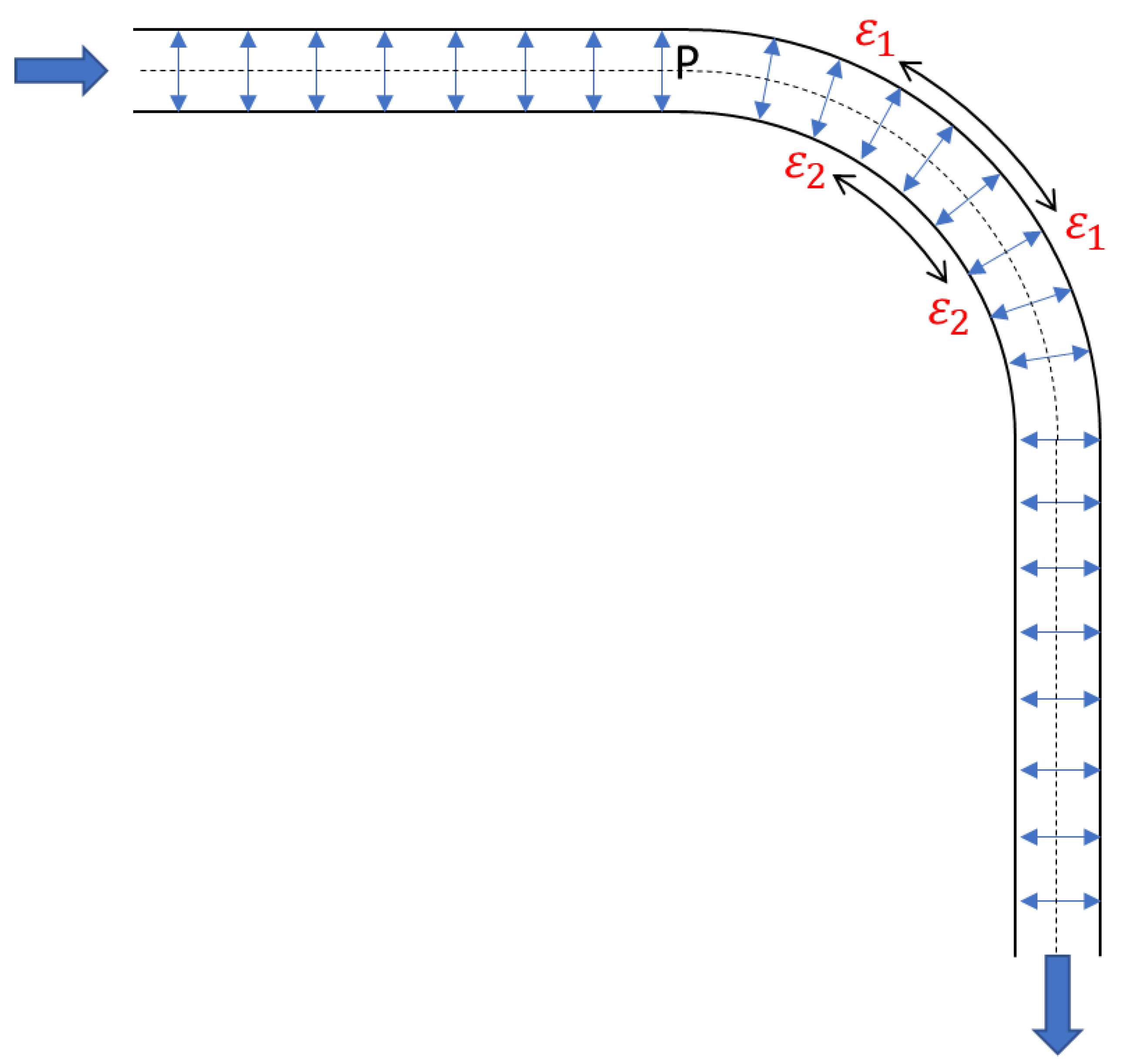
A drawback of the flow rate-measuring techniques described thus far, especially the cantilever-based instruments, is their invasive nature in the fluid domain. To address this disadvantage, a recent study, published in 2022 by Li et al., reports the development of a noninvasive FBG-based flow rate instrument [
50]. In this study, two FBGs are placed on opposite sides of a
bend in a pipe, specifically at the apex:
along the curve of the bend. When the fluid changes direction as it passes through the bend of the pipe, it exerts a force upon the pipe walls, causing them to slightly deform as shown in
Figure 1. This distortion arises from the inertia of the fluid as well as the hydraulic effects instigated by the centrifugal force acting on the fluid. When the pipe walls deform, the FBGs aligned upon them experience an axial strain, causing a shift in their Bragg wavelength. The greater the flow rate, the greater the Bragg wavelength shift. By monitoring this shift in the Bragg wavelength, and using a differential interrogation method to account for temperature cross sensitivity, the integral flow rate through the bend is determined from the strain-induced wavelength shift of the FBGs [
50].
2.2.3. Speed of Sound
The rate at which pressure waves propagate through a multiphase flow is heavily influenced by the void fraction due to the compressibility effects of gases. The propagation rate of these pressure waves is typically referred to as the speed of sound, and they arise from eddy-induced pressure fluctuations in a turbulent flow [
51]. This is an important parameter to understand to help infer flow regimes within a pipe.
Noninvasive optical flowmeters have been developed, utilising FBGs, that are able to measure the speed of sound, flow rate and direction, within a pipe [
52]. When a sound wave travels through a fluid, the density and pressure of the flow medium will vary. This creates a small, radially acting, variable pressure from the fluid against the pipe wall, changing the pipe’s diameter by a small amount as the pressure wave passes. This can be described using Equation (
7) [
52]. If an optical fibre, with FBGs created upon it, is wrapped around the external surface of a pipe, this slight expansion of the pipe’s diameter imposes a strain along the optical fibre, producing a proportional shift in the reflected spectra of the FBGs:
where
is the change in the pipe radius (
m),
is the change in the radially acting pressure (
),
r is the pipe radius (
m),
E is Young’s modulus of the pipe (
), and
t is the time over which the pressure changes (
s) [
53].
If multiple optical fibres are wrapped around the outside of a pipe at a known distance from each other, then the speed of sound and flow rate can be calculated based on the time difference between the FBGs of each fibre coil detecting the pipe diameter expansion. It should be noted that this expansion is a combination of effects arising from both pressure wave propagation and turbulent eddies acting against the pipe walls [
53]. For the application, where flows impose rapidly varying dynamic strains on a pipe, low-reflectivity FBGs interrogated through interferometric techniques are commonly used due to the high resolution and sensitivity this method provides [
52].
Optical flowmeters of this type have been extensively utilised in the oil and gas industry to analyse multiphase flows, including the in-well instrumentation measuring flow rate, direction and void fraction, and have been commercialised [
53,
54,
55,
56]. However, as discussed in
Section 3 and
Section 4.1, no example of this technology being utilised in nuclear thermal hydraulic experiments has been identified. Therefore, optical fibre-based flowmeters, and other related instrumentation developed within the petrochemical industry, represent an interesting technological suite that may greatly benefit nuclear thermal hydraulic research when applied in prototypical experimental facilities.
2.2.4. Void Fraction and Flow Regime Identification
Under certain flow conditions, different phases of a fluid can have different densities and can travel at different velocities within a multiphase fluid as it flows along a pipe. However, it should be noted that liquids and gases can have comparable properties at higher temperatures and pressures [
51,
57]. If an FBG on an optical fibre is positioned across a pipe so that the FBG is centred in the middle of the pipe and perpendicular to the flow direction, then the hydrodynamic forces exerted on the fibre by the fluid will depend on the phase of the fluid interacting with the sensor. The denser the fluid, the greater the exerted force, the greater the axial strain along the FBG, and thus, the greater the strain-induced Bragg wavelength shift from the FBG [
58]. Therefore, in a liquid–gas two-phase flow, the greater the void fraction, the smaller the strain-induced Bragg wavelength shift caused by the fluid interacting with the FBG. In a 2012 study by Baroncini et al. [
58], this principle was utilised to create an FBG-based instrument for the characterisation of multiphase flow. This was achieved by using a three-grating FBG array that was passed through a test section, as described above, so that each FBG was positioned in the centre of the test section and at an axial distance of 5 cm from the next FBG along the pipe. When an air/water slug flow was passed through the sensing region, the resulting strain-induced Bragg wavelength shifts, and the times between these shifts, were observed, allowing for the void fraction and fluid velocities to be inferred. These results were then compared to the void fractions and fluid velocities measured by two coaxially aligned wire mesh sensors. From this comparison, it was found that both the FBG and wire mesh sensors produced the same overall trend in their measured variations in the void fraction, with the numerical values being in reasonable agreement. Furthermore, the fluid velocity measured by both sensors were in good agreement for liquid phase velocity values of less than 2 m·s
but began to diverge beyond this value [
15,
58].
Additionally, hybrid instruments, where conductivity or impedance-based probes are co-operated with optical fibre sensors, have been demonstrated [
12,
59]. In these instruments, the sensing principle of the FBG elements remains the same as described above, whereas the electrical-based components of the system utilise the difference in conductivity of the different phases of a fluid to determine the phase of the fluid interacting with the sensor, similar to the operation of a WMS. An instrument using this principle was investigated by Winter et al. [
12]. In this study, changes in the electrical and optical signals from the sensor were monitored, allowing for the presence of bubbles interacting with the sensor to be detected, theoretically allowing for the determination of flow regime and void fraction—though this is yet to be explicitly demonstrated for this hybrid-type instrument [
60]. Similarly, FBGs have been incorporated into hot-wire anemometers, which utilise the temperature sensitivity of FBGs to measure thermal changes in a heated wire arising from the difference in the cooling effects of different phases of a fluid as it interacts with the sensor [
60,
61].
By combining FBGs into existing detector designs it allows the cross validation of data produced simultaneously at the same point in the fluid domain using different sensing techniques—increasing the reliability of the measurements produced by the instrument. Another advantage of this hybrid approach is that it increases the amount of data that can be extracted from a single penetration into the fluid domain without increased flow disruption, allowing for the design of less invasive instruments.
2.2.5. Flow Imaging
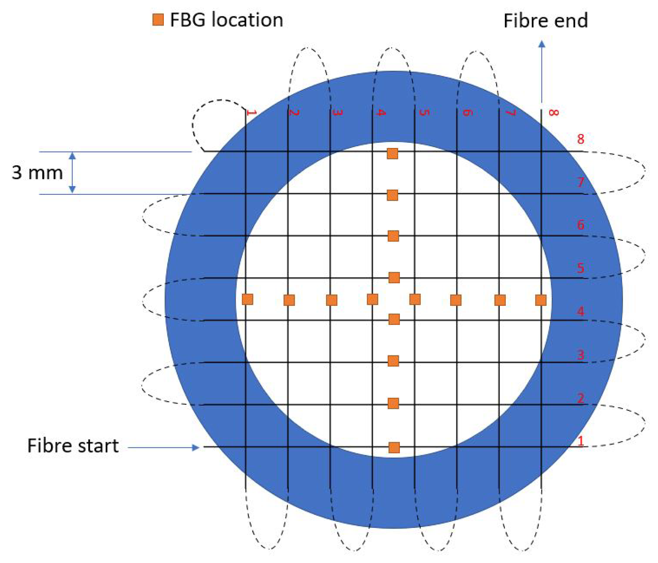
Arguably the most novel and, as determined by this review of the literature, most under-explored application of FBG-based sensors (in the context of thermal hydraulics) is the use of FBG-based instruments for phase structure imaging. While existing phase structure imaging technology exists and is well developed (most notably WMS), FBG-based instruments may provide a number of advantages over existing technologies—such as being operable in conductive fluids at greater temperatures, pressures and flow rates. Despite this, as far as the authors of this review could determine, only one example of this application has been found in the literature, this being the work of Zamarreno et al. [
14,
15,
16,
17]. In these studies, an FBG grid sensor was constructed by concertinaing a 16-grating FBG array from a single fibre into a grid structure; this was in turn held in place, at tension, within grooves cut into a modified flange using adhesive. This created an 8 × 8 grid with an FBG located in the centre of each part of the fibre that crossed the fluid domain, producing eight vertical and eight horizontal sensing points as shown in
Figure 2. This instrument was then installed within a horizontal test section of a light water loop to investigate the capabilities of this sensor in single-phase and multiphase conditions. The principle of operation for this instruments is the same as the sensors described in the previous sub-section for the measurement of void fraction, except that the location of each fibre within the fluid domain is now also used to provide spatial resolution to the measurements produced from this instrument.
To begin with, the instrument’s ability to measure the velocity profile of single-phase flow was investigated. In single-phase flow, there is no difference in the phase density to elicit a difference in the strain-induced Bragg wavelength shift from the FBGs of the sensor. However, especially in laminar flow, the velocity profile of the fluid at a given cross section assumes a quadratic profile, with the peak velocity located in the centre of the pipe. Therefore, basic fluid dynamics theory suggests that the further the distance of an FBG from the centre of the pipe, the lower the fluid velocity in that position, the lower the hydrodynamic forces imparted on the FBG by the fluid, and the lower the axial strain experienced along the FBG, leading to a lower Bragg wavelength shift. By plotting the shift in Bragg wavelength from each FBG at different flow rates in a 2D plot, Zamarreno et al. [
15,
17] showed that this expected behaviour is observed from the distribution of Bragg wavelength shifts across the sensor. Next, the single-phase turbulence monitoring capabilities of the sensor were investigated by observing how the strain-induced wavelength shifts from each FBG varied when the vortices and flow irregularities of turbulent flow imparted varying hydrodynamic forces across the sensor [
17]. From this experiment, it was found that different local hydrodynamic forces could be resolved clearly at flow velocities above 2 m·s
[
15]. Below this value, this could not be achieved, likely due to the lower hydrodynamic force, and lower regional variations in hydrodynamic forces, accompanying a lower flow velocity. Despite this, at flow velocities above this value, different Bragg wavelength shifts were observed—showing the sensor’s use as a single-phase velocity profiler.
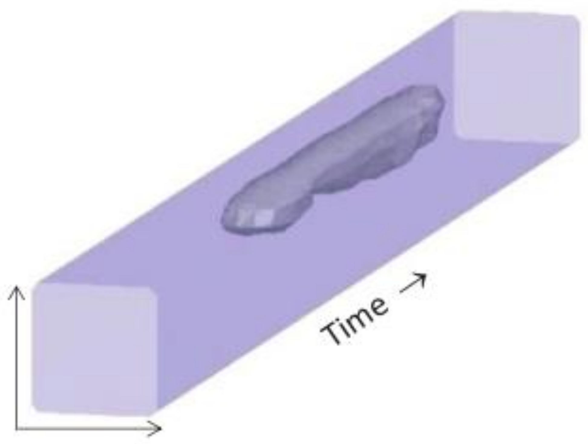
Finally, the two-phase monitoring capabilities of the sensor were explored [
14,
15,
16]. This was achieved by passing an air–water slug flow through the FBG grid sensor and monitoring the strain-induced Bragg wavelength shifts arising from the drop in hydrodynamic force acting on each FBG when the gaseous phase interacted with the sensor. In this experiment, the velocity of the two-phase flow was kept constant at 1.5 m·s
and 0.5 m·s
for the liquid and gaseous phases, respectively [
15]. Because the sensor was installed within a horizontal test section, the bubbles of the slug flow travelled along the top part of the pipe resulting in a decrease in the strain-induced wavelength shift from the upper FBGs. By normalising each recorded Bragg wavelength shift against the maximum Bragg wavelength shift and applying a threshold value corresponding to the normalised wavelength shift which occurs when a bubble interacts with an FBG, it is possible to reconstruct a 2D map of a bubble as it passes through the sensor [
14,
15,
16]. By combining these 2D plots as they vary over time, and using a suitable reconstruction algorithm, it is possible to create a 3D model of the phase structure interacting with the instrument over time, as shown in
Figure 3 [
16]. It should be noted that, due to the cross-sensitivity of FBGs to temperature and strain, efforts should be taken to ensure that the temperature of the fluid remains constant or that other procedures are established to account for this cross sensitivity as discussed in
Section 4.3.
3. FBG-Based Flow Characterisation in Nuclear Thermal Hydraulics Experiments
To best ascertain how FBG-based sensors can be further developed to benefit nuclear thermal hydraulics research, it is first essential to identify how this technology is currently deployed in this field. In this section, a semi-systematic review procedure is first defined and then applied to searching the published literature. For the purposes of this review, flow characterisation in nuclear thermal hydraulics applications is defined as the use of FBGs to analyse fluid flows in prototypical NPP conditions, or industrially relevant analogues. This includes the measurement of a void fraction, imaging of phase structures (such as bubbles), and identification of flow or boiling regime. However, this literature search will exclude FBG-based sensors for measuring general parameters, such as temperature, pressure and vibration (which have been covered in other reviews [
62,
63,
64,
65]), and focus instead on identifying specialised flow characterisation technologies.
For the semi-systematic component of this review, the Web of Science (WoS) and Scopus paper databases were searched to identify published articles and conference papers for combinations of keywords or phrases, starting by searching for articles including the phrases “fibre Bragg gratings” and “nuclear”, before refining the search by iteratively adding one of the following terms to the search criteria: “flows”, “coolant”, “water”, “multiphase”, “hydraulics”, “void fraction”, “boiling”, and “bubbles”. This produced eight unique three-phrase search queries. After completing this search, the collection of papers produced from both databases, following the removal of any duplicates, consisted of 37 publications. From this collection, any articles relating to non-nuclear applications were removed, leaving 20 publications. The papers that were removed during this initial filtering processes typically related to medical, nuclear magnetic resonance, or structural monitoring applications. The remaining papers were then read and filtered again, removing any papers that did not meet the above-defined nuclear thermal hydraulics applications definition. Strikingly, this just left two papers.
The first of these papers, a 2011 overview paper by Willsch et al. [
66], discussed a range of applications of fibre optics sensor arrays in a power plant. One such discussed application was the velocity profiling of a single-phase gas flow, taken from an earlier work of Willsch et al. [
67]. In this study, an FBG array was combined with heated wire anemometer principles by co-axially aligning an optical fibre, with FBGs multiplexed upon it, alongside a heated wire. As an inhomogeneous gas flow passes over the sensor, the varying flow rates of a given cross section will cool the heated wire by different rates at different positions along its length, producing different temperature-induced Bragg wavelength shifts of the fibre’s FBGs, depending on the FBGs location in the flow. The higher the flow rate, the greater the cooling, and the more substantial the Bragg wavelength shift. By calibrating Bragg wavelength shifts to different flow rates, measurements of the velocity profile of the gas can be produced.
The second identified paper, published by Villanueva et al. in 2022 [
68], includes the use of FBG arrays for studying melt infiltration and solidification within the Multicomponent Remelting, Relocation, and Solidification in Porous Debris (MRSPOD) facility. In these experiments, FBG arrays were utilised to measure the melt pool height and position of a eutectic Sn–Bi melt infiltrating a particle bed, enabling investigations to gain a better understanding of the behaviour of molten fluids, such as corium, in a NPP accident scenario. This demonstrates a nuclear thermal hydraulic application of FBGs, outside of the more typical thermal hydraulic studies of coolants.
Beyond the two papers emerging from the filtering process of this systematic review, it should also be noted that other publications were identified that reported FBGs being utilised in prototypical NPP conditions—but for applications outside of the scope of this review. These include measuring temperature [
69,
70], vibrations [
71,
72,
73], and structural monitoring applications [
74,
75].
Moreover, to identify any relevant publications that met the aforementioned “nuclear thermal hydraulics applications” definition that were not found during the systematic review, a less exhaustive literature review was also conducted by entering the same eight search queries into Google Scholar. This produced a large, but generally less relevant, set of articles and conference papers. Nevertheless, the first twenty papers of each Google Scholar search was manually checked, reducing the likelihood that no relevant publications were missed. After applying the same filtering process, this produced no additional publications describing nuclear thermal hydraulics applications of FBG-based sensors.
4. Discussion
4.1. Commentary on Literature Review Results
Despite finding examples of FBG-based sensors being developed to characterise various properties of multiphase flows in the published literature; such as for the measurement of void fractions, flow velocity profiles, and for the imaging phase structures—as seen in the works of Allil et al. [
45], Baroncini et al. [
58], and Zamarreno et al. [
14,
15,
16,
17] mentioned in
Section 2.2—no study was identified in the literature, by this systematic review, which detailed the application of these techniques to nuclear thermal hydraulics experiments or related fundamental studies. Nonetheless, this review did identify two papers [
67,
68] that showcased FBGs being applied to explore industrially relevant thermal hydraulic phenomena. Given the many desirable characteristics of optical fibres and FBGs, including their high temperature, high pressure and corrosion resistance, this indicates a potential large area of under-explored research opportunities to develop and use FBG-based instruments targeted for nuclear thermal hydraulics research. Therefore, in the following sections, the advantages and disadvantages of FBG-based sensors for flow characterisation are discussed, alongside the potential applications of these techniques.
4.2. Advantages of FBG-Based Instruments for Flow Characterisation
The FBG-based instrumentation techniques described in
Section 2.2 all share a number of advantages that highlight the benefits of using FBG-based sensors for flow characterisation; these include good resistance to high temperatures and high pressures as well as corrosion tolerance and durability. For example, Zhang et al. [
76], demonstrated in 2007 that an FBG can be fabricated that functions as a temperature sensor for conditions up to 1100 °C. This sensor is able to operate reliably with a steady and clear response, but a 25% drop in reflectivity at temperatures over 1000 °C was reported [
76]. This temperature is far above the operating temperatures of typical light water reactors and even well above those seen in the advanced coolants of many novel reactor concepts. Similarly, the pressure resistance of FBGs has been well reported, such as by Hong et al., who produced an FBG sensor capable of withstanding pressures up 45 MPa through a temperature range of −10 °C to 300 °C [
77]. The durability and corrosion resistance of FBGs, even under high temperatures, has also been well documented as shown by Pauw et al. [
73], and Grandal et al. [
78], who demonstrated the ability of FBGs to measure temperature and strain even when immersed in molten lead–bismuth and molten salt flows, respectively. These are highly desirable characteristics for instruments intended for use in nuclear thermal hydraulics experiments and related industrial applications, especially for experimental research into advanced, fourth generation reactor designs, where operating conditions can significantly exceed the temperature and pressure limits of existing instrumentation, and then particularly when considering sensors for flow characterisation and imaging.
The multiplexability of FBGs also enables the creation of multiple sensing points on a single fibre used in an invasive FBG-based sensor, allowing for more data collection without increased flow disruption from the instrument.
Additionally, because of the flexible nature and small diameter of optical fibres (typically between 50–550
m [
79,
80]), FBG-based sensors can be used to create both embedded instrumentation and novel sensor geometries [
79]. In terms of flow characterisation, this can allow for the design of noninvasive and minimally invasive instrumentation, reducing or removing disruption to the fluid domain.
Moreover, despite limited published work characterising and comparing the mechanical properties of different optical fibres and fibre coating materials, it has been reported that commercially available optical fibres have high moduli of elasticity, experience minimal plastic deformation and have good ultimate tensile strength, reinforcing the justification of using optical fibres to produce resilient instruments to be used in harsh conditions [
81,
82]. However, it should be noted that the characterisation of the mechanical properties of optical fibres at high temperatures (in excess of 100 °C) has not been subjected to extensive research, and should be the target of future projects.
Another desirable trait of FBG-based instruments is the high data acquisition rates achievable by interrogators, with common commercial interrogators available with sample rates up to 40 kHz [
83]. However, work by Bentell et al. reports the development of an FBG interrogator with a 250 kHz sample rate [
84]. This is a highly beneficial characteristic for instruments designed to image phase structures or measure void fractions via changes in strain across an FBG because of the limited time that phase structures have to interact with a sensor in a high flow rate environment. In work published by Zamarreno et al., it is reported that an FBG grid sensor designed to image phase structures was unable to image fast-moving phase structures and turbulent velocity profiles when its interrogator’s sample rate was below 800 Hz [
15].
Table 1 provides a selection of published examples that showcase the desirable properties of FBG sensors, in the context of thermal hydraulics experiments.
4.3. Disadvantages and Limitations of FBG-Based Instruments for Flow Characterisation
The advantages of FBG-based instruments for fluid analysis are partially offset by a number of the limitations of optical fibre technology. These limitations manifest both as surmountable challenges, to be targeted by future research, and the intrinsic disadvantages of using FBG-based instruments for flow characterisation. The following subsections identify and discuss these issues.
4.3.1. General Disadvantages and Limitations
A property of FBGs that must be addressed in the design of all instruments or experiments utilising FBGs is the cross sensitivity of FBGs to changes in both temperature and strain. This is because, without proper measures to deconvolute these effects, it is challenging to isolate shifts in the Bragg wavelength of an FBG arising from changes in temperature from those arising from changes in strain [
87]. Nevertheless, this limitation can be mitigated using a range of proven and established methods. For example, instruments based on the strain sensitivity of FBGs can account for the effects of temperature variations by selecting fibres and fibre coating materials with small thermal expansion and thermo-optic coefficients, leading to the FBG being significantly more sensitive to changes in strain than temperature, minimising the cross-sensitivity effect [
36,
88]. Another approach is to utilise two FBGs: one exposed to temperature and strain variations, the other exposed to the same temperature variations but isolated from other effects imposing strain on the sensor. By comparing the reflected spectra of the FBG effected only by temperature (the reference FBG) to the reflected spectra of the FBG affected by both temperature and strain (the sensor FBG), the contribution of temperature on the Bragg wavelength shift can be removed, allowing the sensing of strain to be isolated [
89]. Conversely, temperature can be isolated from strain by photo-inducing birefringence in an FBG during manufacture. This causes the two orthogonal polarisations of light to experience different refractive indices, producing two separate peaks in the reflected spectra, which can be optimised to have different sensitivities to temperature and strain, allowing for simultaneous, and decoupled measurements, of both parameters [
87,
90,
91]. Alternatively, an FBG sensor can simply be placed within a thermowell before being inserted into a fluid domain to prevent the fluid from imparting a strain on the FBGs. There have also been efforts to address cross sensitivity by utilising machine learning to distinguish changes in the Bragg wavelength of an FBG arising from either temperature or strain [
92].
Furthermore, as most FBG-based instruments for fluid analysis take the form of probes or grids inserted into the fluid domain, a disadvantage common to most FBG-based instruments is their invasive nature. This may constitute a significant limitation of FBG sensors when used to image the propagation of phase structures within a fluid. This is because the presence of the instrument will disrupt the flow of the fluid, thus effecting the propagation of phase structures beyond the instrument. However, at higher temperatures, and because of the small diameter of optical fibres, the breakup of bubbles caused by an invasive FBG probe or grid sensor will be minimised due to the surface tension of the gas–liquid interface decreasing as temperature increases—promoting bubble recombination [
93].
Lastly, striking a balance between over- and under-engineered FBG flow characterisation solutions is well worth consideration, particularly given the context that no current FBG grid sensor has yet been mass produced, introducing cost considerations for custom prototype instruments. As market prices are fluctuating and inflationary pressures remain applied in the aftermath of the COVID-19 pandemic (and other crises) with uneven global recovery, the procurement of raw materials for the production of bespoke mechanical and electronic instruments has become increasingly costly and difficult.
4.3.2. FBG and Fibre Material Limitations
Many unanswered questions exist concerning the environmental and mechanical reliability of existing optical fibres, including how these properties change over extended time scales and in harsh conditions. A challenge is also presented when attempting to compare and generalise the properties of optical fibres, as most published studies that present FBG-based instruments use custom fibres or fibre coatings and do not report an accompanying analysis of these materials’ properties [
82]. This restricts an assessment of the material limitations of optical fibres on the design of FBG-based instruments for flow characterisation. Furthermore, when analysis of the mechanical properties of optical fibres is published, the range of temperatures and pressure for which the material has been characterised is generally significantly below the conditions relevant to nuclear thermal hydraulics experiments. Therefore, in order to advise the design of future FBG sensors and fibre optic systems in harsh conditions, more extensive research into the characterisation of the environmental, mechanical, and dimensional stability of optical fibres is essential.
Despite the limited published material regarding the mechanical properties of optical fibres, following discussions with a range of FBG manufacturing companies, an often described material limitation of optical fibres is their low modulus of rigidity, indicating susceptibility to breaking via shear forces. This is an important factor to consider when designing instruments for flow characterisation, as the hydrodynamic forces imparted on a sensor inserted into a fluid domain may prove sufficient to break the fibre, limiting the applications in which FBG-based instruments can be deployed. Remediating approaches to this limitation have been developed, such as encasing fibres in steel capillaries [
94], aligning fibres axially along the fluid domain [
73], and coating optical fibres in materials to improve their mechanical properties [
78,
95]. Nevertheless, when designing an FBG-based sensor, it is important to account for the material limitations of optical fibres, especially when designing instruments intended to be transversely inserted into a fluid domain, or used in high flow rates or in high-viscosity fluids. This consideration is particularly important for nuclear thermal hydraulics research, as a sensor of this type is yet to be demonstrated under prototypical NPP flow rates.
Additionally, although the flexibility of optical fibres is a useful characteristic when designing novel instrument geometries, the optical critical bending radius of the fibre must be considered. This value, which is separate and potentially larger than the mechanical critical bending radius of the fibre, denotes the minimum radius through which an optical fibre can be bent without significantly increasing signal attenuation—also known as bending loss [
96,
97]. While this limitation can be addressed when designing an instrument by ensuring that both the optical and physical bending radii are not violated, this property of optical fibres may pose situational limitations, such as when designing sensors for use in small diameter pipes with small bending radii, similar to those found within boiler tube bundles.
Another property of the fibre material that should advise the design of FBG-based sensors is the significance of the birefringence effect within a fibre. Birefringence is the property of a material to have a different refractive index depending on the propagation direction and polarisation of the light interacting with the material [
98]. This may arise from the material properties of the fibre or from deformation of the fibre by external stress, giving the fibre a non-circular cross section [
99]. Hence, birefringence can cause undesirable modifications to the properties of an electromagnetic wave being transmitted along an optical fibre, such as pulse broadening, frequency shifts or changes in a wave’s polarisation state [
99]. This effect poses a particular issue when utilising optical fibres for telecom applications, as data are encoded into the properties of the transmitted waves, which can be altered by birefringence. In the context of FBG-based sensors, the main limitation introduced by birefringence is polarisation-dependent frequency shifts (PDFSs), which produce wavelength shifts in the reflected spectra. These wavelength shifts arising from PDFS are typically sub-picometer in magnitude but can be as large as 40 pm, decreasing a sensor’s accuracy [
100].
4.3.3. Light Source and Interrogator Electronics Limitations
Monitoring shifts in the Bragg wavelength of an FBG necessitates the selection of appropriate light source and optical analysis electronics. These electronics should enable the accurate, low noise, high sensitivity and high sample rate monitoring of the reflected spectra from an FBG. It is the limitations of these electronics that can ultimately restrict the performance of an FBG-based instrument regardless of the properties of the selected optical fibre. To begin with, consider the properties of the light source used by an interrogator. Typically, this will be either a superluminescent diode (SLD) or a laser. Both of these options have their own advantages and disadvantages. For example, the well-defined narrow-band wavelength width of light emitted from a fibre laser diode allows for low noise and high precision reflected spectra to be produced from an FBG [
101]. However, this same narrow-band characteristic of laser light significantly limits the number of FBGs that can be interrogated along a single fibre [
102]. In addition, as laser light is heavily polarised, the effect of PDFSs on the peak wavelength of the reflected spectra is more significant than for non-polarised light, leading to a reduction in accuracy [
102]. However, this same polarisation allows for the birefringent decoupling of temperature and strain effects from a suitably optimised FBG [
87]. Conversely, SLDs allow for the interrogation of a greater number of FBGs upon a single optical fibre. This is because of the greater range of available wavelengths for multiplexing from a broad band light source. Also, as the light emitted by SLDs originate from both amplified and spontaneous emissions, the produced electromagnetic waves are not fully polarised, reducing the effect of PDFS on the reflected spectra [
103]. Nonetheless, the lower spectral power density of SLDs, when compared to laser light sources, elicits a weaker response from FBGs that in turn increases measurement uncertainty and noise, especially across long fibre lengths [
101].
In addition, when using FBG sensors for the measurement of void fraction or the imaging of phase structures, the data acquisition rate of the chosen interrogator is essential. If this rate is too small (indicating poor temporal resolutions), then because of the short interaction time that phase structures have to interact with a sensor inserted into a fluid domain, the brief change in Bragg wavelength arising from the variation of strain experienced by an FBG might not be recorded. While limited experimental work has been conducted to identify a data acquisition rate threshold below which a sensor would be unable to detect different phases in multiphase flow, Zamarreno et al. reported that a sample rate above 800 Hz was required to image fast-moving phase structures and turbulent velocity profiles for their FBG grid sensor [
15].
4.4. Future Applications of FBG-Based Sensors in Nuclear Thermal Hydraulics Experiments
4.4.1. Harsh Environment Flow Characterisation
The study of molten metal or molten salt flows, such as those within proposed fourth generation reactor designs, presents experimental conditions where current flow characterisation techniques will struggle to be practically applied. For instance, due to the opaque nature of molten coolant multiphase flows, PIV techniques cannot be utilised because of the requirement of optical access to the bulk of the fluid to observe the movement of particles. Similarly, for molten lead flows (depending on the diameter of the fluid domain), lead’s high attenuation of gamma rays will largely limit the application of radiation densitometry or tomography techniques. Furthermore, the conductivity of metal coolants, as well as the high operating temperatures, will also limit the utilisation of WMS. However, none of these properties of molten coolants immediately prevents the use of FBG grid sensors, as FBGs can operate at temperatures above that of molten lead, are unaffected by a fluid’s conductivity or electromagnetic effects, and have mechanical properties which, if properly optimised, may enable the instruments to withstand the hydrodynamic forces imparted on the sensor by the flow. Nevertheless, significant future work is still needed to successfully develop and validate this concept, including exploration of the wetting effects of molten lead on optical fibres, as well as an in-depth characterisation of the mechanical properties of optical fibres at temperatures from 450 °C to 750 °C [
104,
105,
106]. If such an FBG grid sensor can be developed, the authors hypothesise that the ability of the instrument to distinguish between different phases in a molten coolant multiphase flow will be superior to the sensors’ performance in water–steam flows due to the greater difference in densities between the phases. An application for which an FBG-based instrument could be particularly well suited is the profiling of temperature or velocity gradients for a given cross section of a molten flow. This enables the study of the stratification properties of advanced reactor coolants, including the solidification behaviours of liquid metal and molten salt coolants.
4.4.2. Counter Flow and Cross Flow Analysis
Furthering our understanding of counter flow and cross flow in multiphase fluids, such as those observed in flooding phenomena in water-cooled reactor accident scenarios [
107,
108] or as generally occurring in reactor core structural geometries, will greatly assist the design of new water-cooled reactors and improved thermal hydraulic reactor simulation codes. This necessitates the development of flow imaging instrumentation that is not only capable of reproducing the shape of phase structures but also determining the direction of their propagation. Therefore, because of the development of direction-sensitive flow rate sensors based on FBGs [
48,
109], an interesting research opportunity is presented by investigating whether these concepts can be incorporated into an FBG grid sensor or a similar instrument. If successfully developed, this instrument would not only be able to image phase structures as they pass through the sensor but also produce a cross section of the regional flow directions.
The study of counter-flow and cross-flow phenomena could also be furthered by using the same optical fibre flowmeter technology used in the petrochemical industry for in-well instrumentation as presented in
Section 2.2.3. This technology is capable of accurately determining flow rate and direction through analysis of pipe wall deformation by the flow conditions within. For example, consider a T-junction study, where each branch of the junction is equipped with a flow meter of this type. In such an experiment, these sensors may be able to deliver insights into the flow effects that arise when fluid from the third branch is injected across the main flow at different temperatures and pressures—provided each fibre loop of the sensors are suitably close together to detect small flow reversal effects [
110]. These sensor will have an advantage over FBG grid sensors or WMS in this application, given their ability to resolve flow direction, enabling the analysis of dynamic 3D effects along a length of a pipe without disrupting the flow. Moreover, the same technology could also be used to study boiling regimes in prototypical conditions, where the noninvasiveness and temperature resistance of this sensor type lends itself for use in large-scale rigs for validating new SMR designs.
4.4.3. Flow Imaging
Arguably the most insufficiently researched application of FBG-based instruments, in the area of flow characterisation, is the use of FBGs to create grid sensors to image phase structures and turbulent velocity profiles within a fluid. The properties of optical fibres and FBGs, alongside the limited published research into this application (which is presented in full in
Section 2.2.5) demonstrates the potential benefits of this technology to expand flow-imaging capabilities.
Due to the limited published research regarding the design of FBG grid sensors for flow imaging, future designs of FBG grid sensor can improve upon the published examples via a number of small iterations. For example, the spatial resolution of these sensors can be improved by simply increasing the number of FBGs on each fibre, as well as the number of fibres (or passes of a fibre) that cross the fluid domain. This increases the number of data points that can be used to reconstruct a model of a bubble as it passes through the sensor. However, it should be noted that there is a limit to the number of FBGs that can be multiplexed and interrogated on a single fibre: usually between 20 and 60 FBGs using currently available commercial interrogators. Additionally, the temporal resolution of FBG grid sensors can be improved by designing or utilising higher sample rate interrogators to increase the frequency of data capture.
4.5. Cost and Maintenance Considerations
The cost of an FBG-based sensor is influenced by two main factors: the environmental conditions of the target application, and the number of FBGs. For example, the higher the temperature or shear strain applied against an FBG, the more robust or bespoke the selected fibre coating or fibre encapsulation technique must be. For nuclear thermal hydraulic applications, where high temperature and flow rates are present, this is an important consideration. For example, an FBG encapsulated in a steel capillary will cost significantly more, from commercial manufacturers, than a polyimide-coated fibre. Similarly, emerging fibre coatings or manufacturing techniques, such as those suitable for use in temperatures over 1000 °C, are not widely commercially available [
76]. This introduces additional costs, especially when prototyping. Furthermore, following discussions with commercial FBG manufacturers, it was also noted that the number of FBGs created upon an optical fibre is a significant driver of the cost of the array. This is a key consideration in the design of FBG grid sensors when a high number of FBGs are required to achieve the desirable spatial resolution.
The maintenance of such a sensor is also expected to be low, given the environmental robustness of optical fibres. However, in a sensor consisting of one FBG array concertinaed into a grid, if one crossing strand of the sensor breaks, then all FBGs further along the array will also fail. To prevent this, sensors could be designed so that each crossing strand is a separate optical fibre, which would be easier to replace, increasing the overall resilience of the sensor to damage, but also increasing the overall cost.
4.6. Thermal Hydraulics Open-Access Research (THOR) Facility
Bangor University’s Nuclear Futures Institute (NFI) has deployed two facilities on Anglesey’s Menai Science Park (M-SParc). The first of these facilities is the Thermal Hydraulics Open-access Research (THOR) facility. This is a highly modular light water thermal hydraulic loop designed to support a wide range of experiments and packaging integration options for flow imaging instrumentation—including WMS, high-speed cameras, and prototype FBG grid sensors—in most parts of its loop structures, including dedicated test sections, pumping loop sections and its main pressurisation vessel. Later, this instrumentation suite should be expanded further to include PIV, and noninvasive fibre optic flowmeters for studying flow speed, flow regime and phase fraction as described in
Section 2.2.3. This will allow for the study of dynamic flow phenomena over the length of a pipe geometry, complementing the higher-resolution cross-sectional analysis achievable with WMS and FBG grid sensors at a given point.
The initial maximum operating temperature and pressure of the facility is 200 °C and 16 bar, respectively, allowing for a range industrially relevant thermal hydraulic experiments to be conducted, including flow obstruction, multiphase heat transfer and T-junction flow studies. The flexible design of THOR allows for significant future upgrades of these system operating parameters, providing increasingly challenging environments for components and instrumentation testing to proceed through in the years to come. Alongside this rig, Bangor University’s Lead Loop for Erosion/corrosion Testing (BULLET) has also been constructed. This facility comprises a molten lead flow loop optimised for material testing but can also be adapted in the future for molten lead fluid dynamics studies.
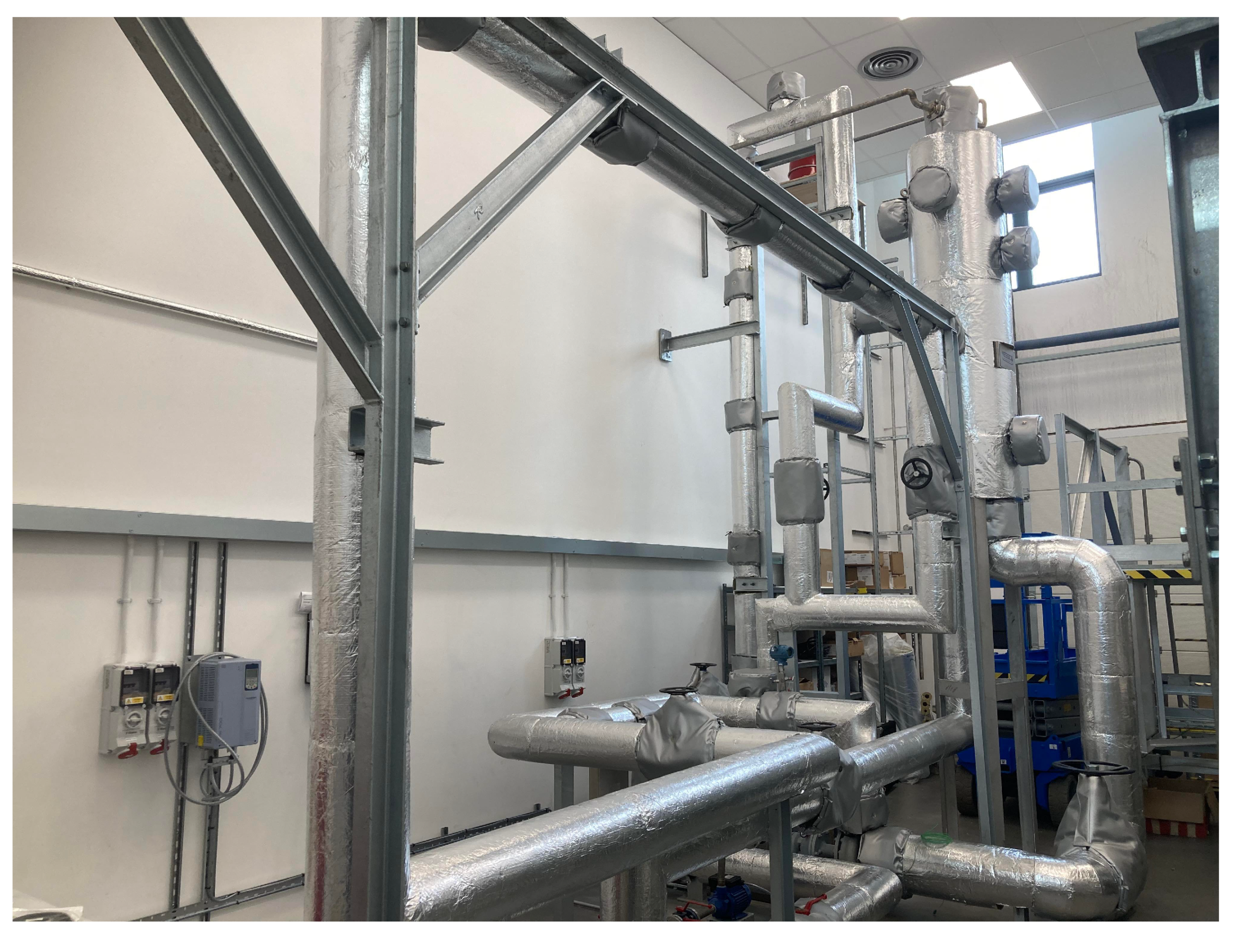
In its initial configuration, the THOR facility allows for WMS and FBG grid sensors to be installed between the flanges of either the facility’s vertical or horizontal 4 m modular test sections as shown in
Figure 4. In addition to this flow imaging instrumentation, the THOR facility is outfitted with a range of other instruments to record measurements of flow rate, pressure, and temperature across the system in real time. Moreover, this facility will be utilised by researchers within the NFI to develop improved FBG grid sensors by assessing their ability to image water–steam flows at high temperatures and pressures. Comparisons can then be made between the performance of WMS and FBG grid sensors within the facility. This rig will also be utilised to explore how the cross sensitivity of FBGs will be affected by the rapidly varying temperatures and strains encountered in different boiling regimes.
5. Concluding Remarks
Despite the adoption of FBG sensors by a wide range of industries over the last four decades, the use of FBG-based instrumentation for flow characterisation in nuclear thermal hydraulics research is ripe for further development. Of particular significance is the substantially under-researched use of FBG grid sensors for void fraction measurement using multiphase flow imaging. This technology shows great potential to complement existing multiphase flow characterisation techniques by providing a technology that can operate in scenarios where existing flow characterisation techniques (such as WMS, PIV, ultrasound, or radiation densitometry) cannot be practically applied.
After conducting this analysis of the published literature, several research opportunities for expanding the capabilities of FBG-based instruments were proposed and discussed. It is hoped that these suggested research directions will enable future FBG grid sensor developments to be optimally targeted to benefit nuclear thermal hydraulics research. For example, to better reconstruct images of bubbles that pass through an FBG grid sensor, it is recommended that sensors are designed with a greater number of optical fibres to enable more FBGs (and fibre passes) to be inserted into a fluid domain, increasing a sensor’s spatial resolution. Low-reflectivity FBGs and interferometric techniques should also be explored as ways to increase instrument sensitivity and resolution. Furthermore, noninvasive optical fibre flowmeters, as mentioned in this report and commonly used in the oil and gas industry, should also be considered as instrumentation in nuclear thermal hydraulic experiments, given their ability to resolve flow direction and phase fraction.
Accompanying the proposed future research on new sensor designs should be efforts to develop optical fibres with enhanced mechanical properties to improve an FBG grid sensor’s resilience to hydrodynamic shear forces imparted upon it, especially at high temperatures. Additionally, advances in FBG multiplexing and superposition techniques, alongside research on improved data reconstruction algorithms and higher sample rate interrogators, will also significantly benefit this flow imaging technology.
Finally, beyond water thermal hydraulic studies, a scenario where FBG grid sensors can further benefit nuclear thermal hydraulic research is the study of molten salt and liquid metal flows, such as those within the proposed advanced, fourth generation nuclear reactor designs. The high-temperature, high-density, conductivity, and translucent or opaque nature of these coolants prevents or limits the use of existing flow characterisation technologies. However, these properties of molten salt and liquid metal coolants do not immediately exclude the use of FBG-based sensors—especially when fibre encapsulation is considered. This could enable the design of temperature and velocity profiling instruments for molten coolant experiments, demonstrating the importance of further research to assess the feasibility of this proposed application.


