Article

Comparing CrN and TiN Coatings for Accident-Tolerant Fuels in PWR and BWR Autoclaves

1
Department of Physics, Chalmers University of Technology, 412 96 Gothenburg, Sweden
2
Department of Chemistry and Chemical Engineering, Chalmers University of Technology, 412 96 Gothenburg, Sweden
3
KTH-Royal Institute of Technology, 114 28 Stockholm, Sweden
4
Westinghouse Electric Sweden AB, 721 63 Västerås, Sweden
*
Author to whom correspondence should be addressed.
J. Nucl. Eng. 2022, 3(4), 321-332; https://doi.org/10.3390/jne3040019
Submission received: 8 September 2022 / Revised: 11 October 2022 / Accepted: 1 November 2022 / Published: 4 November 2022

Abstract

:
The development of coatings for accident-tolerant fuels (ATFs) for light water reactor (LWR) applications promises improved corrosion resistance under accident conditions and better performances during operation. CrN and TiN coatings are characterized by high wear resistance coupled with good corrosion resistance properties. They are generally used to protect materials in applications where extreme conditions are involved and represent promising candidates for ATF. Zr cladding tubes coated with 5 µm-thick CrN or TiN, exposed in an autoclave to simulated PWR chemistry and BWR chemistry, were characterized with SEM, EDS, and STEM. The investigation focused on the performance and oxidation mechanisms of the coated claddings under simulated reactor chemistry. Both coatings provided improved oxidation resistance in a simulated PWR environment, where passivating films of Cr2O3 and TiO2, less than 1 µm-thick, formed on the CrN and TiN outer surfaces, respectively. Under the more challenging BWR conditions, any formed Cr2O3 dissolved into the oxidizing water, resulting in the complete dissolution of the CrN coating. For the TiN coating, the formation of a stable TiO2 film was observed under BWR conditions, but the developed oxide film was unable to stop the flux of oxygen to the substrate, causing the oxidation of the substrate.

1. Introduction

The development of accident-tolerant fuels (ATFs) for light water reactors (LWRs) has been proposed to offer new materials that are able to withstand severe accident conditions and to improve the performance of the currently used Zr alloys [1,2]. In LWRs, the cladding tube encloses the fuel pellets and prevents any release of radioactive material into the cooling water. The main degradation mechanisms that affect Zr claddings under accident conditions are rapid oxidation and hydrogen pick-up [3]. Cladding degradation is critically detrimental to safety and accident management, as it can lead to severe consequences. Two proposed solutions to the need for ATFs are: the integral substitution of the Zr cladding with a cladding material that is better able to endure severe accident conditions and the application of a protective coating on top of the currently used cladding tubes. FeCrAl alloys [2,4] and SiC/SiC composite materials [2,5] are currently being studied as substitutes for Zr alloys, but their implementation in commercial reactors might still take some time. Coatings such as metallic Cr and a wide range of ceramic coatings are instead being investigated as possible short-term answers for ATFs [6,7,8]. Chromia-forming coatings, metallic Cr in particular [8,9,10,11], have emerged as highly effective under accident conditions, while they are able to improve performance during operation in pressurized water reactors (PWRs), but no coating has been identified yet for use in boiling water reactor (BWR) operating conditions.
Nitride coatings display very good corrosion properties and offer very high hardness values that can help protect against debris fretting (one of the most common rod failure modes [12,13]), making them promising candidates for both PWR and BWR [2,14,15,16,17,18,19]. CrN is meant to form a Cr2O3 passivating layer that is able to stop the diffusion of oxygen and significantly slow any oxidative process [6,20], both during operation and in the event of an accident. TiN, instead, is expected to form TiO2 as a passivating layer [21,22]. Nitride coatings have been widely investigated for such applications and have demonstrated improved corrosion resistance in air [23] and supercritical water [24] and improved resistance to abrasion [25]. CrN coatings have been tested in high-temperature steam (simulating a loss-of-coolant accident) and have demonstrated excellent steam oxidation resistance [26,27,28]. It is worth mentioning that CrN starts decomposing into Cr and N2 gas above 1000 °C, and this results in the formation of porosities in the coating when exposed to high-temperature steam corrosion. Nonetheless, the presence of such porosities did not deteriorate the performance of the coating. CrN was shown to be able to withstand these temperatures for the duration of the tests, allowing the CrN-coated cladding to clearly outperform the uncoated cladding [26]. The coatings in this study were obtained with cathodic arc physical vapor deposition (arc-PVD), one of the most commonly used deposition techniques for nitride coatings and thin films. In arc-PVD, a diffuse electric arc discharge is used to enhance the kinetic energy of the atoms on the target surface so as to create a very dense plasma that is then driven to the sample by a magnetic field [29]. Arc-PVD allows the production of fully dense nitride coatings layer by layer, with excellent control of the chemical composition of the final coating [29,30,31]. The obtained coatings are usually characterized by textured, columnar grains aligned with the growth direction [29,32].
In this work, the corrosion protection properties of arc-PVD CrN and TiN coatings were tested in an autoclave simulating both PWR and BWR water chemistries. The coatings were deposited onto a Zr alloy cladding tube, then exposed to the simulated operating environment and characterized with a range of electron microscopy techniques. Scanning electron microscopy (SEM) was used to study the morphology of the as-fabricated coating and the coating after exposure. Energy-dispersive x-ray spectroscopy (EDS) was used to measure the compositions of the coatings and to understand what type of oxide developed on the coated samples in the different environments. Scanning transmission electron microscopy (STEM) was used to access smaller details in some of the tested samples. Schematic corrosion mechanisms for each material and environment are proposed.

2. Materials and Methods

2.1. Materials

CrN- and TiN-coated HiFi® Zr-claddings, in the form of tubes that were 4 cm-long and 10 mm in diameter, were analyzed. Both as-fabricated samples, coated with 5 µm-thick coatings, and material exposed to autoclave corrosion testing were studied. The coatings were obtained by arc-PVD onto HiFi® alloy cladding tubes (1.50 wt.% Sn, 0.40 wt.% Fe, 0.10 wt.% Cr, 0.08 wt.% Ni, and balance Zr [33]). The coating deposition was performed by IonBond IHI Group (Zurich, Switzerland), and the CrN and TiN coatings utilized in this study are two of their commercial products. The PWR exposure was performed in a static, closed steam loop autoclave at 415 °C and 220 bar for a total of 90 days in PWR chemistry. The test temperature for a static steam autoclave according to ASTM is 400 °C [34], but a temperature of 415 °C was chosen to exert more intense corrosion on the specimens. The BWR exposure was performed in a once-through circuit and water autoclave at 360 °C and 220 bar for a total of 60 days in BWR chemistry. Beside the duration, the main difference between the two chemistries was that in the BWR autoclave exposure the oxygen content was monitored and kept constant at 8 ppm. In the PWR autoclave, the oxygen content was below 45 ppb.

2.2. Sample Preparation and Analysis

A low-speed saw was used to cut the received samples into rings 5 mm in height. The rings were embedded in conductive Bakelite and ground and polished with SiC paper and diamond particle suspensions. TEM specimens were extracted from the Bakelite-embedded samples with a dual-beam focused ion beam/scanning electron microscope (FIB/SEM) on a Versa 3D workstation from FEI (Hillsboro, OR, USA) while implementing standard procedures for sample preparation [35,36]. The SEM and EDS analyses, conducted on a GAIA3 microscope from TESCAN (Brno, Czech Republic), allowed us to access the morphology, microstructure, and chemistry of the exposed samples. STEM imaging was conducted on a 7800F Prime microscope from JEOL (Tokyo, Japan).

3. Results

An overview of the results for the exposure of the two different coatings to both the PWR and BWR chemical environments is displayed in Figure 1. Here, cross-sectional SEM images and the corresponding EDS maps are presented and help visually track the oxidation of the coatings, the chemistry of the formed oxide, and the overall performance of the coated claddings. Both as-fabricated coatings appeared to be single-phase and homogeneous. No porosities were found in the coatings, and the coating–substrate interface appeared smooth and continuous. No intermixing between the coating and the substrate was visible at this scale. The CrN and TiN coatings performed well in the PWR environment forming, respectively, a Cr-rich oxide and a Ti-rich oxide on the outer surface. However, when exposed to BWR environment, both coatings failed to protect the substrate, and ZrO2 could be found after the exposure. Hence, a first important general finding that can be extracted from Figure 1 is that the BWR autoclave environment appears to be significantly more challenging for the tested materials, as expected from the higher amount of dissolved oxygen. Interestingly, even if the BWR exposure conditions were identical for CrN and TiN, the two coatings failed following two different mechanisms.
CrN dissolved completely, leaving behind the bare surface of the cladding that was then attacked by the corrosive environment to form a few-micrometer-thick ZrO2 layer. TiN did not dissolve. Instead, it fully oxidized, transforming into TiO2, which appeared to be stable under these conditions. However, oxygen managed to reach the substrate anyway, and ZrO2 could be found growing at the coating–substrate interface. In this process, the TiO2 appeared to have peeled off from the substrate, leaving a gap between the ZrO2 and the TiO2.

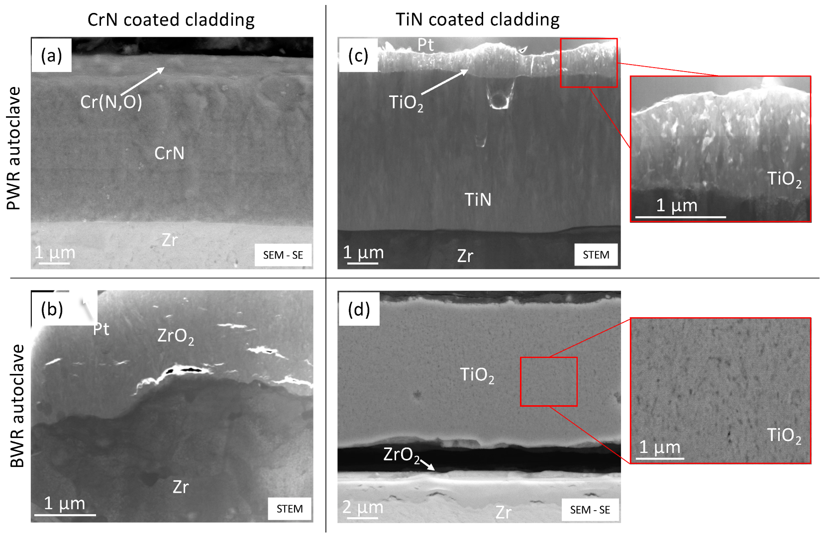
3.1. CrN-Coated Cladding Tubes in PWR Autoclave

In the second row of Figure 1a, the O signal shows that a thin O-enriched layer grew on the outer surface of the CrN-coated cladding after the PWR exposure. From this EDS map, it is difficult to tell the thickness of this band and if N can also be found in it. To better quantify the amount of O enrichment and the composition of this band, an EDS point analysis was performed, and the results are summarized in Table 1a. From the EDS point analysis, it is clear that the measured composition of the as-fabricated coating approached 50 at.% Cr and 50 at.% N, fitting the expected stoichiometry of the CrN compound. A similar composition was measured from the bulk of the coating after PWR autoclave exposure, demonstrating that a major part of the coating had not been oxidized during the corrosion testing. Fluctuations around the 50/50 composition can be attributed to deposition inhomogeneities, local fluctuations, and measurement inaccuracy. The composition of the outer layer of the coating after PWR exposure was measured to be around 50 at.% Cr, 28 at.% N, and 22 at.% O. This composition suggests that the formation of a Cr (N,O) phase (chromium oxynitride) was the main phenomenon occurring during exposure. Details of the Cr (N,O) band are displayed in Figure 2a, and from this SEM image it is possible to see that around 1 µm of Cr (N,O) formed on the surface of the coating. The layer appeared to be dense, and the interface with the underlying CrN coating was flat and continuous without any porosity. The remaining portion of the coating appeared to be unmodified by the exposure.

3.2. CrN-Coated Cladding Tubes in BWR Autoclave

No trace of the CrN coating was left after exposure in the BWR autoclave, as demonstrated by the EDS maps presented in the third row of Figure 1a. The EDS map showed no signal from Cr or N from the outer surface of the cladding when measured on the cross-section. The EDS point analysis confirmed that the coating was dissolved and was substituted by a 2 µm-thick layer of ZrO2. This oxide layer is shown in Figure 2b. It was similar to any zirconia scale that would grow onto an uncoated cladding, but it was significantly thinner than the scale that developed on the uncoated HiFi® cladding tested under similar conditions [37]. It is reasonable to imagine that the CrN coating, while dissolving, offered some protection to the substrate, delaying the onset of its oxidation.

3.3. TiN-Coated Cladding Tubes in PWR Autoclave

The measured composition of the as-fabricated TiN coating, presented in Table 1b, was around 45 at.% Ti and 55 at.% N. The stability range for TiN is relatively wide [38], and the measured composition fell reasonably within this range. The same Ti/N ratio was measured for the TiN coating bulk after the PWR exposure, with the difference that after PWR exposure the coating seemed to have absorbed a small amount of O as well. As shown in Figure 1b, the TiN coating formed a stable 1 µm-thick oxide scale under these conditions, but O seemed to be able to penetrate the scale and reach the coating. The EDS analysis of this oxide confirmed it to be TiO2 with a measured composition of 33 at.% Ti and 66 at.% O. A higher magnification STEM image of the TiO2 scale is presented in Figure 2c, and here the scale appears dense, with little or no porosities and with crystallites in the 100 nm range.

3.4. TiN-Coated Cladding Tubes in BWR Autoclave

Different from the CrN coating, the TiN coating did not dissolve in the BWR environment. TiN oxidized, and it was then able to survive the entire 60 days of exposure as TiO2. The main drawback, visible in Figure 1b and Figure 2d, was that oxygen was able to penetrate the oxidized coating and reach the substrate. As a result, ZrO2 could be observed at the coating–substrate interface. The formation of both TiO2 and ZrO2 came with significant volume expansion, which could lead to the peeling of the TiO2 from the substrate. A detailed SEM image of the cross-section is shown in Figure 2d, where it is possible to notice the presence of a significant number of porosities distributed uniformly in the TiO2 scale. The composition of both oxides was measured with an EDS point analysis, and the results are contained in Table 1b. The measured compositions fit well with the stoichiometry of the two compounds, but the oxygen content in the TiO2 was slightly higher than expected. The allowed composition range for TiO2 is 63–67 at.% O [39], so higher amounts of O might have to be attributed to gas [40] or liquid trapped in the large number of porosities that developed in the oxide layer.

3.5. Overall Performance of the Coatings

A summary of the coating performance is given in Table 2. In PWR autoclave corrosion testing, the CrN-coated cladding formed 1 µm of Cr (N,O), but the rest of the coating and the substrate were unaffected. TiN-coated cladding formed 1 µm of TiO2, and a small concentration of O could be detected in the bulk of the coating. Neither of the tested coatings survived the BWR autoclave corrosion testing. CrN dissolved completely, and the underlying substrate oxidized, forming 2 µm of ZrO2. TiN fully oxidized into TiO2, and oxygen managed to penetrate to the substrate. ZrO2 formed at the coating–substrate interface, and the TiO2 layer was found to be peeling off of the substrate.

4. Discussion

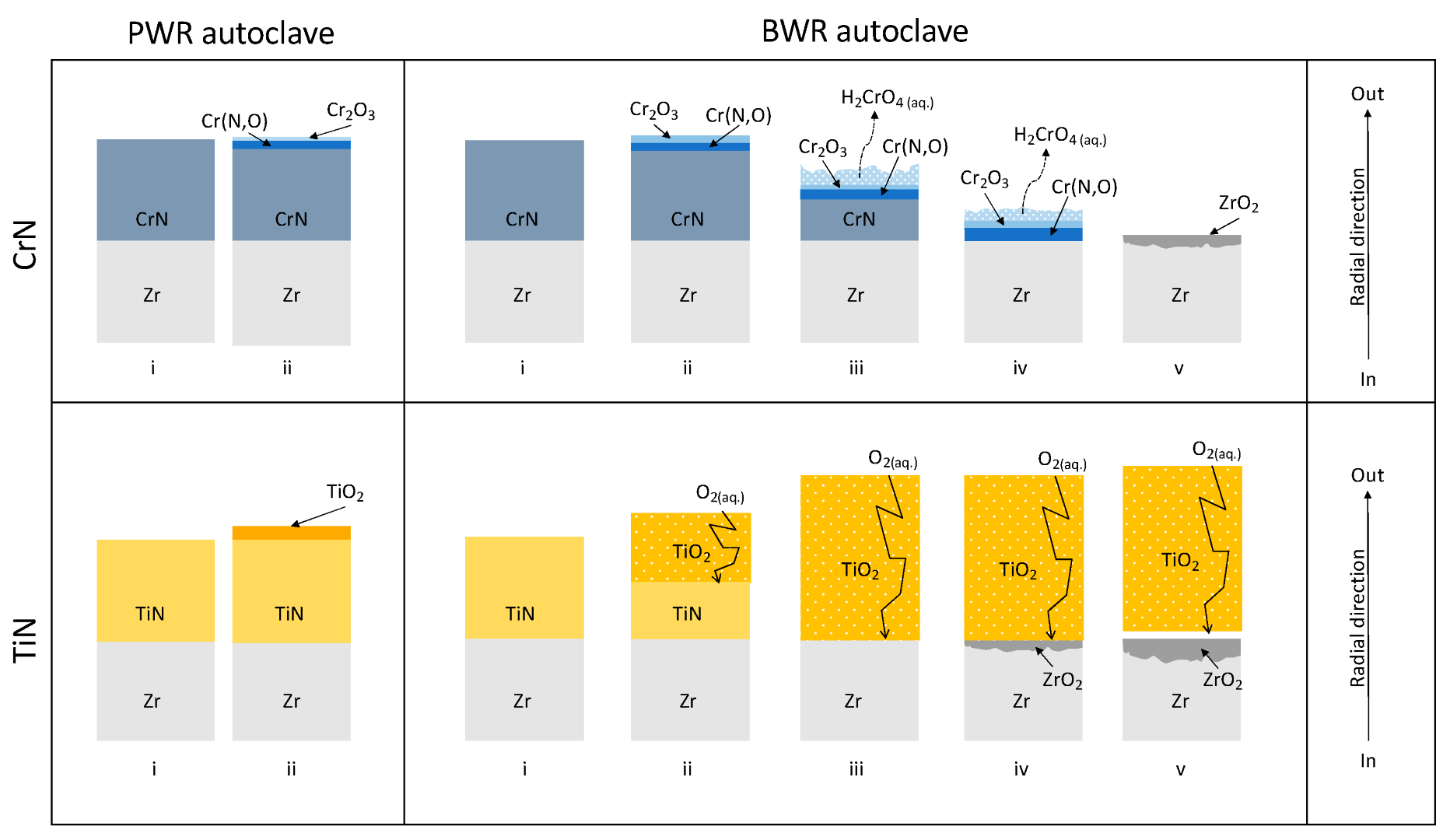
4.1. Oxidation of CrN and the Stability of Cr2O3 in the PWR and BWR Chemical Environments

It is generally accepted in the literature that the oxidation of CrN coatings involves the substitution of N by O in the CrN lattice, which leads to the formation of chromium oxynitrides [20,21,40,41,42]. The N, released as N2 [43] or NH3 [41,44,45], is progressively substituted by O to the point where the nucleation of chromia (Cr2O3) occurs and an oxide scale forms on the surface of the CrN coating. Chromia, once formed, acts as a diffusion barrier for the entrance of oxygen into the coating, slowing the oxidation and effectively passivating the surface of the coated material. For this reason, the stability of chromia in the corroding environment used for the exposure is crucial in determining if the coating will be protective. If chromia is stable or its dissolution rate is very low, the oxidation of the coating stops. However, if the chromia layer starts dissolving, the oxidation of the coating is allowed to progress, more Cr (N,O) forms, and it subsequently transforms into new Cr2O3, which likewise dissolves. This process of the transformation and dissolution of the CrN coating progresses until the entire coating is dissolved and the substrate becomes exposed.
To study the thermodynamic stability of compounds in specific chemical environments and to establish if a material is going to corrode or passivate, Pourbaix diagrams are often used. These diagrams summarize chemical and electrochemical equilibria, at a specific temperature and pressure, in a potential–pH space. The resulting maps are used to predict the absence of corrosion (immunity), the formation of a solid reaction product (passivation), or the formation of a dissolved reaction product (corrosion). Pourbaix diagrams for Cr in water at the temperature of 350 °C and 250 bar (high subcritical water), close to the BWR autoclave conditions, and 400 °C and 250 bar pressure (low supercritical water), close to the PWR autoclave conditions, were calculated by Cook et al. [46]. When calculating these diagrams, a concentration of dissolved species of 10 8 mol/kg, representative of the high-purity water used in power plants [46,47,48] and in the current corrosion tests, was assumed.
In the diagram calculated at 400 °C, a region of stable Cr2O3 stretches across the entire range of pH. Chromia can be further oxidized into H2CrO4 (aq.) and dissolved for higher values of electrochemical potential (i.e., at high concentrations of oxidizing species in the water), but the low concentration of oxygen in the simulated PWR environment makes this unlikely. Any Cr2O3 formed in this chemical environment is likely to be stable, and passivation of the coating can occur. This is in agreement with the experiments. The CrN coating tested under similar conditions in this study appeared to be able to survive with little or no modification or dissolution into the autoclave water, as demonstrated by Figure 1a and Figure 2a.
At 350 °C, no stable Cr2O3 can be found in the Pourbaix diagram. As a consequence, pure metallic Cr is predicted to dissolve directly into H2CrO4 (aq) without forming any Cr2O3. It is difficult to imagine what exactly would happen for CrN or Cr (N,O), but the strategy behind the use of CrN coatings for corrosion resistance stands on the assumption that the developed Cr2O3 will be stable in the chemical environment of interest. If this passivating oxide is not thermodynamically stable, no passivation can be expected, and corrosion is likely to proceed. This is what the results of the BWR autoclave corrosion test presented in Figure 1 and Figure 2 would suggest happened to the CrN coating. In order to have stable chromia at 350 °C, a higher concentration of dissolved species would be needed, as the Pourbaix diagram calculated at 10 6 mol/kg shows a region of stable Cr2O3. Even under such conditions, the formed chromia can dissolve in water as H2CrO4 (aq) for high electrochemical potential values. Hence, the relatively high concentration of oxygen (8 ppm) in the BWR autoclave can probably push the system into the corrosion field, even if a higher solute concentration in the water would theoretically allow for the formation of chromia. A possible sequence of the chemical reactions that would lead to the dissolution of the coating is presented in Equations (1) and (2). These chemical reactions are formulated according to the proposed oxidation mechanism of nitrides [44] and the dissolution of chromia [46] in oxygenated water:
2 CrN s + 3 H 2 O aq   Cr 2 O 3 s + 2 NH 3 aq
2 Cr 2 O 3 s + 4 H 2 O aq + 3 O 2 aq   4 H 2 CrO 4 aq
In PWR, the CrN coating is expected to oxidize into Cr (N,O) and then into Cr2O3. Chromia would be stable in this chemical environment and would stop further oxidation, effectively passivating the coating. This Cr2O3 layer is likely extremely thin and not visible in Figure 2a. However, in BWR water chemistry, chromia is not stable, and the coating is expected to oxidize and subsequently dissolve into the water, as confirmed by the presented experiment. The transformation of CrN into Cr (N,O) probably still occurs, but the products of any further oxidation of the coating are dissolved into the water, progressively consuming the coating down to the Zr substrate. A schematic of the two proposed mechanisms is presented in the first row of Figure 3.
Overall, the role of the oxygen activity in determining the stability of chromia and the consequent passivation of the oxidizing surface is well-established in the literature [46,47,49,50], and it appears to be a very important factor to consider when deciding where to use a chromia-forming coating if effective passivation needs to be achieved. The dissolution of chromium oxide films on steels or Ni alloys, for example, can be avoided by employing Fe and Ni in the alloy, which can form other solid oxides, producing protective oxide layers on top of the chromia scale. In the case of CrN, this protection mechanism cannot be triggered, as there is no other element that can oxidize to form other solid oxides. Hence, the stability of chromia in the tested environments is the only factor that can determine the passivation or corrosion of such coatings. Previous autoclave corrosion studies in BWR water chemistry on CrN coatings for ATF applications have suggested that this coating could survive the BWR environment [51]. In the mentioned work, the oxygen content used for the exposure was not stated. It is possible that the oxygen content chosen for the test did not represent a significant challenge for the formation of Cr2O3. The concentration of 8 ppm of dissolved oxygen in water employed in this work is representative of the actual oxygen concentration in the cooling water of a BWR in the top part of the cladding tube, where steam is present [52], and the resulting dissolution of the CrN coating shows how important this parameter is when assessing oxidation resistance.

4.2. Oxidation of TiN and the Protectiveness of TiO2 in the PWR and BWR Chemical Environments

As for CrN, the oxidation of TiN involves the substitution of N with O with the formation of Ti (N,O), followed by further oxidation of the oxynitride into TiO2 [20,21,53]. The formation of TiO2 was observed in both the PWR and the BWR autoclave experiments, as shown in Figure 1b and Figure 2c,d. However, the effectiveness values of the TiO2 films formed in the PWR and BWR autoclaves were very different. Both oxide films appeared to be stable, but TiO2 seemed to be able to passivate the system in the PWR water chemistry, while a small degree of substrate corrosion could be observed in the BWR environment. The stability of TiO2 in the test conditions was confirmed by the Pourbaix diagram calculated by Cook et al. [46].
The TiO2 film developed under simulated PWR conditions on the TiN-coated cladding displayed in Figure 2c appeared to be compact with no porosities. As a result, the TiO2 film was able to successfully halt the oxidation process. It is worth mentioning that the presence of a small amount of O in the coating bulk indicated that the transition to Ti-oxynitride was initiated in the entire coating. This means that small amounts of oxygen can somehow permeate the TiO2 scale, possibly diffusing along TiO2 grain boundaries to reach the coating. TiO2 is generally not considered the most effective passivating oxide, so the corrosion resistance of Ti alloys is often improved with the addition of elements such as Pd and Pt [54,55]. Similar improvements can be obtained in TiN by adding noble elements or doping with Si [56,57,58,59]. With these modifications, it could be possible to achieve full protection in a PWR environment, improving the performance of the tested TiN coating even further.
However, after the BWR autoclave exposure, the obtained TiO2 film presented a very large number of nanoporosities that could be observed to be uniformly distributed throughout the entire thickness of the oxide scale (see Figure 2d). TiO2 is prone to form porosities, cavities, and other structures, and this peculiarity has often been exploited to obtain nanostructured materials [60,61,62]. The formation of these nanostructures is usually controlled by the addition of elements in the electrochemical environment that promote competition between anodic oxide formation on the outermost surface and the chemical dissolution of the oxide as a soluble complex in crevices [62]. These two phenomena make the growth of a flat oxide surface unstable and foster the formation of pores and crevices. It is therefore possible that the simulated BWR conditions promoted a similar mechanism, causing the porous morphology reported in this work. The resulting TiO2 film was unable to stop the oxygen diffusion, suggesting that the porosities were interconnected into a network of channels, enabling the transport of water, and consequently oxygen, from the outer surface of the TiO2 scale to the coating, fostering the continuous oxidation of the coating. Once the coating was fully transformed into TiO2, the porous oxide scale still allowed water and oxygen to the coating–substrate interface, causing the oxidation of the substrate. The formation of ZrO2 was likely the cause behind the TiO2 delamination [54,63], as the volume expansion induced by the transformation from Zr to ZrO2 produced stresses on the interface. A schematic of the proposed oxidation mechanism is presented in the lower row of Figure 3.

5. Conclusions

CrN and TiN performed well in the simulated PWR environment, offering a significant improvement to the oxidation resistance of the cladding under simulated PWR operating conditions. The 90 days of exposure in the autoclave resulted in the formation of a Cr (N,O) layer less than 1 µm-thick on the outer surface of the CrN coating and no other modifications to the system, making it an excellent candidate for a coated accident-tolerant cladding. A Cr2O3 scale, only a few nanometers thick, at the very surface of the Cr (N,O) layer was likely present, but it could not be confirmed experimentally with SEM-EDS. The TiN-coated cladding developed a 1 µm-thick TiO2 layer that appeared to be able to passivate the coated cladding in the simulated PWR conditions. Small amounts of O could be measured in the bulk of the remaining TiN coating, suggesting that the transformation to Ti-oxynitride was slowly progressing. Small additions to the TiN coating chemistry could possibly result in full protection under simulated PWR conditions.
In the BWR autoclave corrosion test, CrN was fully dissolved during the 60 days of exposure, and a 2 µm-thick layer of ZrO2 was found on the surface of the cladding. The TiN coating oxidized entirely into TiO2. The formed oxide film was porous, and oxygen managed to reach the substrate, causing the formation of a 2 µm-thick ZrO2 layer at the coating–substrate interface. Both coatings appeared to be very effective in the PWR conditions but were only partially effective in the BWR conditions. In BWR chemistry, both coatings could delay the oxidation of the substrate but ultimately ended up exposing the Zr cladding to the reactor water. Interestingly, the failure mechanisms of CrN and TiN in BWR followed completely different paths, as the former was dissolved and the latter oxidized fully into a stable but unprotective scale. Finally, we proposed a schematic representation of the oxidation and degradation mechanism of the two coatings in the PWR and BWR autoclaves. Future work involving advanced analytical methods such as XRD and XPS would allow the confirmation of the proposed mechanisms and a deeper understanding of the corrosion of nitrides in water at these temperatures, pressures, and oxygen concentrations.
The tested environments proved to be very different challenges for the studied materials. While both coatings were shown to be good candidates for ATF in simulated PWR water chemistry, the addition of 8 ppm of dissolved oxygen in the BWR autoclave water caused the coatings to go from practically unaffected to fully dissolved or oxidized. The awareness of the challenges that the BWR environment represents is going to be crucial in the future exploration of possible ATF candidates for this reactor design.

Author Contributions

A.F.: Investigation, Writing—Original Draft, Visualization, and Conceptualization; P.L.: Investigation; D.A.L.: Conceptualization; K.S.: Writing—Review and Editing, and Conceptualization; H.-O.A.: Writing—Review and Editing, and Conceptualization; M.T.: Supervision, Project Administration, Funding Acquisition, Writing—Review and Editing, and Conceptualization. All authors have read and agreed to the published version of the manuscript.

Funding

This project was financially supported by the Swedish Foundation for Strategic Research (SSF) (grant number: EM16-0031).

Data Availability Statement

Not applicable.

Acknowledgments

Westinghouse Electric Sweden is acknowledged for providing the material for the study. All the experimental work presented in this paper was performed at Chalmers Materials Analysis Laboratory (CMAL). Sezgin Cengiz is acknowledged for helping with sample preparation.

Conflicts of Interest

The authors declare no conflict of interest.

References

  1. Zinkle, S.J.; Terrani, K.A.; Gehin, J.C.; Ott, L.J.; Snead, L.L. Accident tolerant fuels for LWRs: A perspective. J. Nucl. Mater. 2014, 448, 374–379. [Google Scholar] [CrossRef]
  2. Terrani, K.A. Accident tolerant fuel cladding development: Promise, status, and challenges. J. Nucl. Mater. 2018, 501, 13–30. [Google Scholar] [CrossRef]
  3. Zieliński, A.; Sobieszczyk, S. Hydrogen-enhanced degradation and oxide effects in zirconium alloys for nuclear applications. Int. J. Hydrogen Energy 2011, 36, 8619–8629. [Google Scholar] [CrossRef]
  4. Sakamoto, K.; Miura, Y.; Ukai, S.; Oono, N.H.; Kimura, A.; Yamaji, A.; Kusagaya, K.; Takano, S.; Kondo, T.; Ikegawa, T.; et al. Development of accident tolerant FeCrAl-ODS fuel cladding for BWRs in Japan. J. Nucl. Mater. 2021, 557, 153276. [Google Scholar] [CrossRef]
  5. Kim, H.G.; Yang, J.H.; Kim, W.J.; Koo, Y.H. Development Status of Accident-tolerant Fuel for Light Water Reactors in Korea. Nucl. Eng. Technol. 2016, 48, 1–15. [Google Scholar] [CrossRef] [Green Version]
  6. Krejčí, J.; Ševeček, M.; Kabátová, J.; Manoch, F.; Kočí, J.; Cvrček, L.; Málek, J.; Krum, S.; Šutta, P.; Bublíková, P.; et al. Experimental behavior of chromium-based coatings. In Proceedings of the TopFuel 2018, Prague, Czech Republic, 30 September–4 October 2018; Volume 156, p. A0233. [Google Scholar]
  7. Wei, T.; Zhang, R.; Yang, H.; Liu, H.; Qiu, S.; Wang, Y.; Du, P.; He, K.; Hu, X.; Dong, C. Microstructure, corrosion resistance and oxidation behavior of Cr-coatings on Zircaloy-4 prepared by vacuum arc plasma deposition. Corros. Sci. 2019, 158, 108077. [Google Scholar] [CrossRef]
  8. Maier, B.; Yeom, H.; Johnson, G.; Dabney, T.; Walters, J.; Xu, P.; Romero, J.; Shah, H.; Sridharan, K. Development of cold spray chromium coatings for improved accident tolerant zirconium-alloy cladding. J. Nucl. Mater. 2019, 519, 247–254. [Google Scholar] [CrossRef] [Green Version]
  9. Brachet, J.-C.; Idarraga-Trujillo, I.; le Flem, M.; le Saux, M.; Vandenberghe, V.; Urvoy, S.; Rouesne, E.; Guilbert, T.; Toffolon-Masclet, C.; Tupin, M.; et al. Early studies on Cr-Coated Zircaloy-4 as enhanced accident tolerant nuclear fuel claddings for light water reactors. J. Nucl. Mater. 2019, 517, 268–285. [Google Scholar] [CrossRef]
  10. Fazi, A.; Aboulfadl, H.; Iyer, A.H.S.; Sattari, M.; Stiller, K.M.; Lokhande, P.; Thuvander, M.; Andren, H.O. Characterization of as-deposited cold sprayed Cr-coating on Optimized ZIRLOTM claddings. J. Nucl. Mater. 2021, 549, 152892. [Google Scholar] [CrossRef]
  11. Fazi, A.; Stiller, K.; Andrén, H.-O.; Thuvander, M. Cold sprayed Cr-coating on Optimized ZIRLOTM claddings: The Cr/Zr interface and its microstructural and chemical evolution after autoclave corrosion testing. J. Nucl. Mater. 2022, 560, 153505. [Google Scholar] [CrossRef]
  12. IAEA. TECDOC-709: Fuel failure in normal operation of water reactors: Experience, mechanisms and management. In Proceedings of a Technical Committee Meeting, Dimitrovgrad, Russia, 26–29 May 1992. [Google Scholar]
  13. Kopeć, M.; Pasta, O.; Mala, M.; Halodova, P.; Cvrček, L.; Krejčı, J. On debris-fretting impact—The study of oxide and chromium layer application. J. Nucl. Eng. Radiat. Sci. 2021, 7, 021802. [Google Scholar] [CrossRef]
  14. Rodrı́guez, R.; Garcı́a, J.; Medrano, A.; Rico, M.; Sánchez, R.; Martı́nez, R.; Labrugère, C.; Lahaye, M.; Guette, A. Tribological behaviour of hard coatings deposited by arc-evaporation PVD. Vacuum. 2002, 67, 559–566. [Google Scholar] [CrossRef]
  15. Bobzin, K.; Lugscheider, E.; Nickel, R.; Bagcivan, N.; Krämer, A. Wear behavior of Cr1−xAlxN PVD-coatings in dry running conditions. Wear 2007, 263, 1274–1280. [Google Scholar] [CrossRef]
  16. Aihua, L.; Jianxin, D.; Haibing, C.; Yangyang, C.; Jun, Z. Friction and wear properties of TiN, TiAlN, AlTiN and CrAlN PVD nitride coatings. Int. J. Refract. Met. Hard Mater. 2012, 31, 82–88. [Google Scholar] [CrossRef]
  17. Tang, C.; Stueber, M.; Seifert, H.J.; Steinbrueck, M. Protective coatings on zirconium-based alloys as accident-Tolerant fuel (ATF) claddings. Corros. Rev. 2017, 35, 141–165. [Google Scholar] [CrossRef]
  18. Liu, J.; Cui, Z.; Ma, D.; Lu, J.; Cui, Y.; Li, C.; Liu, W.; Hao, Z.; Hu, P.; Yao, M. Investigation of oxidation behaviors of coated Zircaloy as accident-tolerant fuel with CrAlN and CrAlSiN coatings in high-temperature steam. Corros. Sci. 2020, 175, 108896. [Google Scholar] [CrossRef]
  19. Chen, S.L.; He, X.J.; Yuan, C.X. Recent studies on potential accident-tolerant fuel-cladding systems in light water reactors. Nucl. Sci. Tech. 2020, 31, 32. [Google Scholar] [CrossRef]
  20. Milošev, I.; Strehblow, H.-H.; Navinšek, B. XPS in the study of high-temperature oxidation of CrN and TiN hard coatings. Surf. Coat. Technol. 1995, 74–75, 897–902. [Google Scholar] [CrossRef]
  21. Esaka, F.; Furuya, K.; Shimada, H.; Imamura, M.; Matsubayashi, N.; Sato, H.; Nishijima, A.; Kawana, A.; Ichimura, H.; Kikuchi, T. Comparison of surface oxidation of titanium nitride and chromium nitride films studied by x-ray absorption and photoelectron spectroscopy. J. Vac. Sci. Technol. A Vac. Surf. Film. 1997, 15, 2521–2528. [Google Scholar] [CrossRef]
  22. Milošv, I.; Strehblow, H.; Navinšek, B.; Metikoš-Huković, M. Electrochemical and thermal oxidation of TiN coatings studied by XPS. Surf. Interface Anal. 1995, 23, 529–539. [Google Scholar] [CrossRef]
  23. Meng, C.; Yang, L.; Wu, Y.; Tan, J.; Dang, W.; He, X.; Ma, X. Study of the oxidation behavior of CrN coating on Zr alloy in air. J. Nucl. Mater. 2019, 515, 354–369. [Google Scholar] [CrossRef]
  24. Khatkhatay, F.; Jiao, L.; Jian, J.; Zhang, W.; Jiao, Z.; Gan, J.; Zhang, H.; Zhang, X.; Wang, H. Superior corrosion resistance properties of TiN-based coatings on Zircaloy tubes in supercritical water. J. Nucl. Mater. 2014, 451, 346–351. [Google Scholar] [CrossRef]
  25. Alat, E.; Brova, M.J.; Younker, I.M.; Motta, A.T.; Fratoni, M.; Wolfe, D.E. Neutronic and mechanical evaluation of rare earth doped and undoped nitride-based coatings for accident tolerant fuels. J. Nucl. Mater. 2019, 518, 419–430. [Google Scholar] [CrossRef]
  26. Liu, J.; Hao, Z.; Cui, Z.; Ma, D.; Lu, J.; Cui, Y.; Li, C.; Liu, W.; Xie, S.; Hu, P.; et al. Oxidation behavior, thermal stability, and the coating/substrate interface evolution of CrN-coated Zircaloy under high-temperature steam. Corros. Sci. 2021, 185, 109416. [Google Scholar] [CrossRef]
  27. Li, Z.; Liu, C.; Chen, Q.; Yang, J.; Liu, J.; Yang, H.; Zhang, W.; Zhang, R.; He, L.; Long, J.; et al. Microstructure, high-temperature corrosion and steam oxidation properties of Cr/CrN multilayer coatings prepared by magnetron sputtering. Corros. Sci. 2021, 191, 109755. [Google Scholar] [CrossRef]
  28. Kashkarov, E.; Afornu, B.; Sidelev, D.; Krinitcyn, M.; Gouws, V.; Lider, A. Recent Advances in Protective Coatings for Accident Tolerant Zr-Based Fuel Claddings. Coatings 2021, 11, 557. [Google Scholar] [CrossRef]
  29. Deng, Y.; Chen, W.; Li, B.; Wang, C.; Kuang, T.; Li, Y. Physical vapor deposition technology for coated cutting tools: A review. Ceram. Int. 2020, 46, 18373–18390. [Google Scholar] [CrossRef]
  30. Özkan, D.; Yılmaz, M.A.; Szala, M.; Türküz, C.; Chocyk, D.; Tunç, C.; Göz, O.; Walczak, M.; Pasierbiewicz, K.; Yağcı, M.B. Effects of ceramic-based CrN, TiN, and AlCrN interlayers on wear and friction behaviors of AlTiSiN + TiSiN PVD coatings. Ceram. Int. 2021, 47, 20077–20089. [Google Scholar] [CrossRef]
  31. Kelly, P.J.; Arnell, R.D.; Ahmed, W.; Afzal, A. Novel engineering coatings produced by closed-field unbalanced magnetron sputtering. Mater. Des. 1996, 17, 215–219. [Google Scholar] [CrossRef]
  32. Postolnyi, B.O.; Araujo, J.P. Structural analysis of Arc-PVD multilayer metal nitride coatings CrN/MoN using electron backscatter diffraction (EBSD). In Proceedings of the 2016 International Conference on Nanomaterials: Application & Properties (NAP), Lviv, Ukraine, 14–19 September 2016. [Google Scholar] [CrossRef]
  33. Karoutas, Z.; Brown, J.; Atwood, A.; Hallstadius, L.; Lahoda, E.; Ray, S.; Bradfute, J. The maturing of nuclear fuel: Past to Accident Tolerant Fuel. Prog. Nucl. Energy 2018, 102, 68–78. [Google Scholar] [CrossRef]
  34. ASTM G2/G2M—19. Standard Test Method for Corrosion Testing of Products of Zirconium, Hafnium, and Their Alloys in Water at 680 °F or in Steam at 750 °F; ASTM: West Conshohocken, PA, USA, 2019. [Google Scholar] [CrossRef]
  35. Thompson, K.; Lawrence, D.; Larson, D.J.; Olson, J.D.; Kelly, T.F.; Gorman, B. In situ site-specific specimen preparation for atom probe tomography. Ultramicroscopy 2007, 107, 131–139. [Google Scholar] [CrossRef] [PubMed]
  36. Langford, R.M.; Rogers, M. In situ lift-out: Steps to improve yield and a comparison with other FIB TEM sample preparation techniques. Micron 2008, 39, 1325–1330. [Google Scholar] [CrossRef] [PubMed]
  37. Itagaki, N.; Kakiuchi, K.; Mozumi, Y.; Furuya, T.; Kubota, O. Development of new high corrosion resistance Zr Alloy HiFi for high burn-up BWR Fuel. In Proceedings of the Topfuel—2003 Conference, Würzburg, Germany, 16–19 March 2003. [Google Scholar]
  38. Aghajani, H.; Motlagh, M.S. Effect of temperature on surface characteristics of nitrogen ion implanted biocompatible titanium. J. Mater. Sci. Mater. Med. 2017, 28, 29. [Google Scholar] [CrossRef] [PubMed]
  39. Wagner, I.A.S.; Seifert, H.J. Materials Science International Team, The Binary System Ti-O [99Wal]: Datasheet from MSI Eureka in Springer Materials. 2001. Available online: https://materials.springer.com/msi/phase-diagram/docs/smmsir1001080101fullLnkDia0 (accessed on 5 October 2022).
  40. Milošev, I.; Strehblow, H.-H.; Navinšek, B. Comparison of TiN, ZrN and CrN hard nitride coatings: Electrochemical and thermal oxidation. Thin Solid Film. 1997, 303, 246–254. [Google Scholar] [CrossRef]
  41. Suzuki, K.; Endo, T.; Fukushima, T.; Sato, A.; Suzuki, T.; Nakayama, T.; Suematsu, H.; Niihara, K. Controlling Oxygen Content by Varying Oxygen Partial Pressure in Chromium Oxynitride Thin Films Prepared by Pulsed Laser Deposition. Mater. Trans. 2013, 54, 1140–1144. [Google Scholar] [CrossRef] [Green Version]
  42. Korablov, S.; Ibrahim, M.; Yoshimura, M. Hydrothermal corrosion of TiAlN and CrN PVD films on stainless steel. Corros. Sci. 2005, 47, 1839–1854. [Google Scholar] [CrossRef]
  43. Lin, J.; Mishra, B.; Moore, J.J.; Sproul, W.D. A study of the oxidation behavior of CrN and CrAlN thin films in air using DSC and TGA analyses. Surf. Coat. Technol. 2008, 202, 3272–3283. [Google Scholar] [CrossRef]
  44. Sunder, S.; Miller, N.H. XPS and XRD studies of corrosion of uranium nitride by water. J. Alloys Compd. 1998, 271–273, 568–572. [Google Scholar] [CrossRef]
  45. Somiya, S. Hydrothermal corrosion of nitride and carbide of silicon. Mater. Chem. Phys. 2001, 67, 157–164. [Google Scholar] [CrossRef]
  46. Cook, W.G.; Olive, R.P. Pourbaix diagrams for chromium, aluminum and titanium extended to high-subcritical and low-supercritical conditions. Corros. Sci. 2012, 58, 291–298. [Google Scholar] [CrossRef]
  47. Beverskog, B.; Puigdomenech, I. Revised pourbaix diagrams for chromium at 25–300 °C. Corros. Sci. 1997, 39, 43–57. [Google Scholar] [CrossRef]
  48. Cubicciotti, D. Potential-pH diagrams for alloy-water systems under LWR conditions. J. Nucl. Mater. 1993, 201, 176–183. [Google Scholar] [CrossRef]
  49. Mahboubi, S.; Zurob, H.S.; Botton, G.A.; Kish, J.R. Effect of water vapour partial pressure on the chromia (Cr2O3)-based scale stability. Can. Metall. Q. 2018, 57, 89–98. [Google Scholar] [CrossRef]
  50. Pujilaksono, B.; Jonsson, T.; Halvarsson, M.; Panas, I.; Svensson, J.-E.; Johansson, L.-G. Paralinear Oxidation of Chromium in O2 + H2O Environment at 600–700 °C. Oxid. Met. 2008, 70, 163–188. [Google Scholar] [CrossRef]
  51. Van Nieuwenhove, R.; Andersson, V.; Balak, J.; Oberländer, B. In-pile testing of CrN, TiAlN, and AlCrN coatings on zircaloy cladding in the Halden reactor. In Proceedings of the Zirconium in the Nuclear Industry: 18th International Symposium, Bilbao, Spain, 26–30 June 2022; ASTM International: West Conshohocken, PA, USA, 2018; pp. 965–982. [Google Scholar] [CrossRef]
  52. Ullberg, M.; Gott, K.; Lejon, J.; Granath, G. Advanced ECP model for BWRs. In Proceedings of the Canadian Nuclear Society, 13th International Conference on Environmental Degradation of Materials in Nuclear Power Systems, Toronto, ON, Canada, 19–23 August 2007; pp. 1237–1249. [Google Scholar]
  53. Chen, H.-Y.; Lu, F.-H. Oxidation behavior of titanium nitride films. J. Vac. Sci. Technol. A Vac. Surf. Film. 2005, 23, 1006–1009. [Google Scholar] [CrossRef] [Green Version]
  54. Bloyce, A.; Qi, P.Y.; Dong, H.; Bell, T. Surface modification of titanium alloys for combined improvements in corrosion and wear resistance. Surf. Coat. Technol. 1998, 107, 125–132. [Google Scholar] [CrossRef]
  55. Tomashov, N.D.; Altovsky, R.M.; Chernova, G.P. Passivity and Corrosion Resistance of Titanium and Its Alloys. J. Electrochem. Soc. 1961, 108, 113. [Google Scholar] [CrossRef]
  56. Wiiala, U.K.; Penttinen, I.M.; Korhonen, A.S.; Aromaa, J.; Ristolainen, E. Improved corrosion resistance of physical vapour deposition coated TiN and ZrN. Surf. Coat. Technol. 1990, 41, 191–204. [Google Scholar] [CrossRef]
  57. Steyer, P.; Pilloud, D.; Pierson, J.F.; Millet, J.-P.; Charnay, M.; Stauder, B.; Jacquot, P. Oxidation resistance improvement of arc-evaporated TiN hard coatings by silicon addition. Surf. Coat. Technol. 2006, 201, 4158–4162. [Google Scholar] [CrossRef]
  58. Pfeiler, M.; Scheu, C.; Hutter, H.; Schnöller, J.; Michotte, C.; Mitterer, C.; Kathrein, M. On the effect of Ta on improved oxidation resistance of Ti–Al–Ta–N coatings. J. Vac. Sci. Technol. A Vac. Surf. Film. 2009, 27, 554. [Google Scholar] [CrossRef]
  59. Pfeiler, M.; Zechner, J.; Penoy, M.; Michotte, C.; Mitterer, C.; Kathrein, M. Improved oxidation resistance of TiAlN coatings by doping with Si or B. Surf. Coat. Technol. 2009, 203, 3104–3110. [Google Scholar] [CrossRef]
  60. Saha, S.K.; Park, Y.J.; Cho, S.O. Fabrication of highly ordered nanoporous oxide layer on Ti6Al4V surfaces for improved corrosion resistance property. J. Mol. Struct. 2021, 1223, 129244. [Google Scholar] [CrossRef]
  61. Galstyan, V.; Vomiero, A.; Comini, E.; Faglia, G.; Sberveglieri, G. TiO2 nanotubular and nanoporous arrays by electrochemical anodization on different substrates. RSC Adv. 2011, 1, 1038–1044. [Google Scholar] [CrossRef]
  62. Macak, J.M.; Tsuchiya, H.; Ghicov, A.; Yasuda, K.; Hahn, R.; Bauer, S.; Schmuki, P. TiO2 nanotubes: Self-organized electrochemical formation, properties and applications. Curr. Opin. Solid State Mater. Sci. 2007, 11, 3–18. [Google Scholar] [CrossRef]
  63. Chim, Y.C.; Ding, X.Z.; Zeng, X.T.; Zhang, S. Oxidation resistance of TiN, CrN, TiAlN and CrAlN coatings deposited by lateral rotating cathode arc. Thin Solid Film. 2009, 517, 4845–4849. [Google Scholar] [CrossRef]
Figure 1. SEM cross-section imaging and EDS mapping. (a) CrN coating on HiFi® cladding: as fabricated, after PWR autoclave exposure, and after BWR autoclave exposure. (b) TiN coating on HiFi® cladding: as fabricated, after PWR autoclave exposure, and after BWR autoclave exposure.
Jne 03 00019 g001
Figure 2. SEM and STEM cross-sectional images of the outer surfaces of the coated claddings after autoclave exposure. (a) SEM image of CrN-coated cladding after PWR autoclave exposure; (b) STEM image of CrN-coated cladding after BWR autoclave exposure; (c) STEM image of TiN-coated cladding after PWR autoclave exposure; (d) SEM image of TiN-coated cladding after BWR autoclave exposure.
Jne 03 00019 g002
Figure 3. Schematic of the proposed corrosion mechanisms for CrN and TiN in the PWR autoclave and BWR autoclave environments.
Jne 03 00019 g003
Table 1. Results of EDS point analysis on as-fabricated and autoclave-exposed coated claddings: (a) CrN-coated claddings and (b) TiN-coated claddings.
(a)Analysis LocationConditionsCommentsZr (at.%)Cr (at.%)N (at.%)O (at.%)
CrN coated claddingCoating
(bulk—cross section)
As-fabricatedHomogeneous-47.3 ± 0.352.7 ± 0.3-
Coating
(bulk—cross section)
PWR
autoclave
Homogeneous-53.6 ± 0.346.4 ± 0.3-
Oxidized coating
(outer surface)
PWR
autoclave
Transformation to Cr(N,O)-49.7 ± 0.327.9 ± 0.222.4 ± 0.2
Coating
(bulk—cross section)
BWR
autoclave
No coating left----
Oxidized coating
(outer surface)
BWR
autoclave
No coating left----
Oxidized substrate
(outer surface)
BWR
autoclave
Oxidation of the substrate27.7 ± 0.5--72.3 ± 0.4
(b)Analysis LocationConditionsCommentsZr (at.%)Ti (at.%)N (at.%)O (at.%)
TiN coated claddingCoating
(bulk—cross section)
As-fabricatedHomogeneous-44.8 ± 0.255.2 ± 0.2-
Coating
(bulk—cross section)
PWR
autoclave
Homogeneous-43.6 ± 0.553.2 ± 0.43.2 ± 0.5
Oxidized coating
(outer surface)
PWR
autoclave
Adherent oxide-33.0 ± 0.8-67.0 ± 0.8
Coating
(bulk—cross section)
BWR
autoclave
Coating fully
oxidized
Oxidized coating
(outer surface)
BWR
autoclave
Peeling of the
oxidized coating
-26.8 ± 0.5-73.2 ± 0.2
Oxidized substrate
(interface—cross section)
BWR
autoclave
Oxidation of the substrate30.6 ± 0.4--69.4 ± 0.4
Table 2. Summary of the results of the current study.
CoatingAutoclave Corrosion Test (PWR)Autoclave Corrosion Test (BWR)
CrNCoating consumed: negligible Coating consumed: 100%
Oxide thickness—type: <1 µm—Cr(N,O)Oxide thickness – type: ∽2 µm—ZrO2
TiNCoating consumed: negligibleCoating consumed: 100%
Oxide thickness—type: <1 µm—TiO2Oxide thickness – type: ∽10 µm—TiO2 + ∽2 µm—ZrO2
Publisher’s Note: MDPI stays neutral with regard to jurisdictional claims in published maps and institutional affiliations.

