
Neutronics Analyses of the Radiation Field at the Accelerator-Based Neutron Source of Nagoya University for the BNCT Study

 ,
,  ,
,
Abstract
:1. Introduction
2. Methods
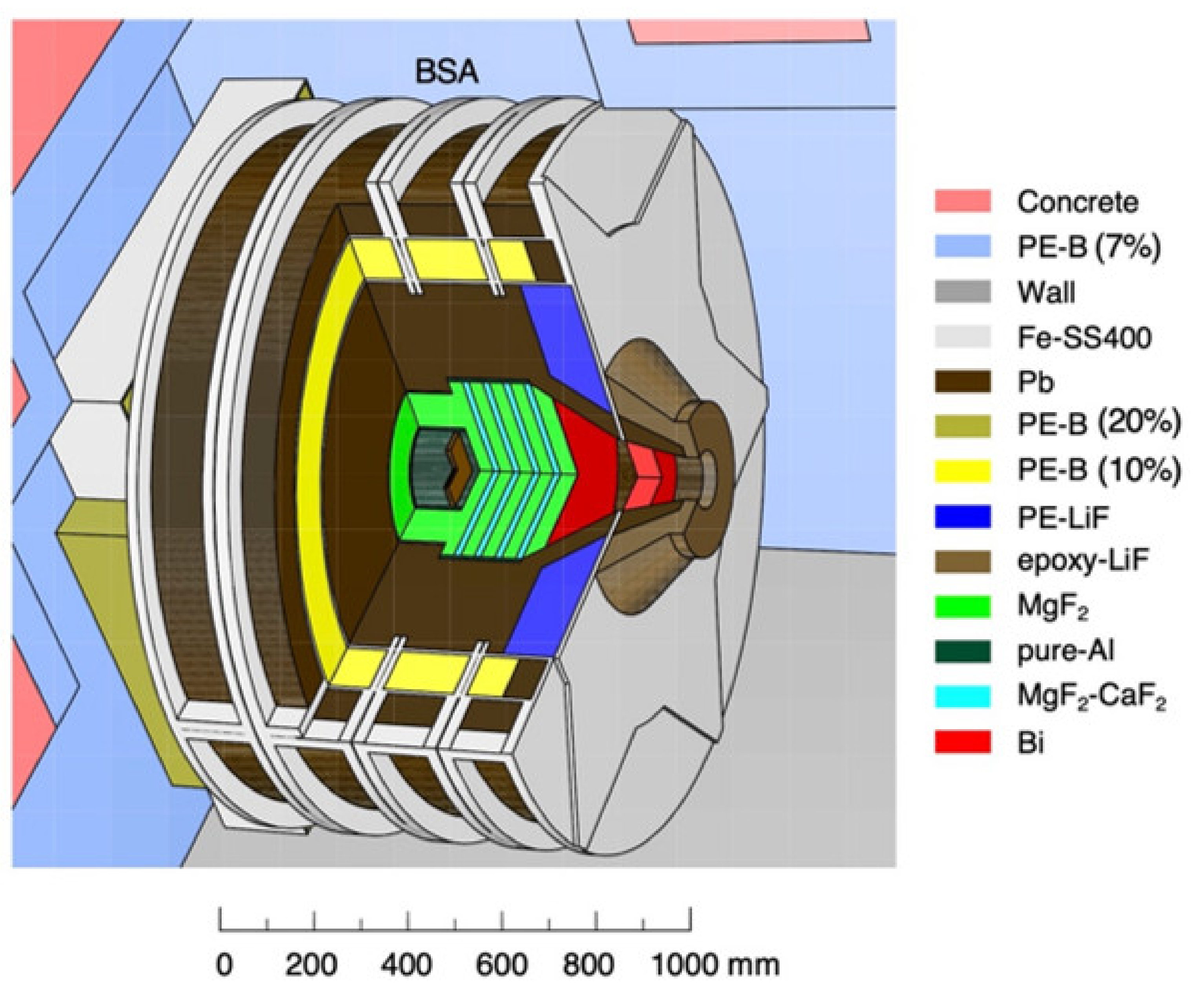
2.1. NUANS Facility
2.2. Computational Methods
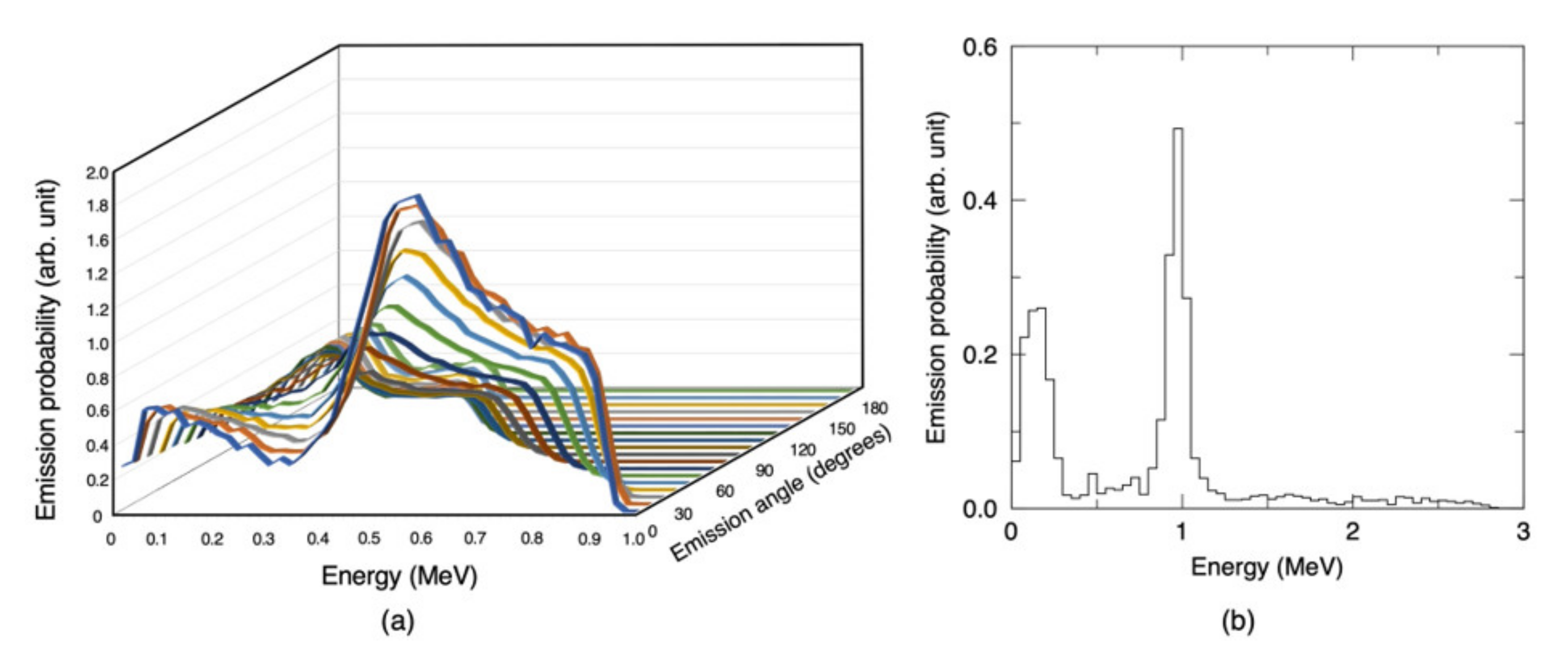
2.3. Neutron and Gamma-ray Source Term at the Lithium Target
3. Results
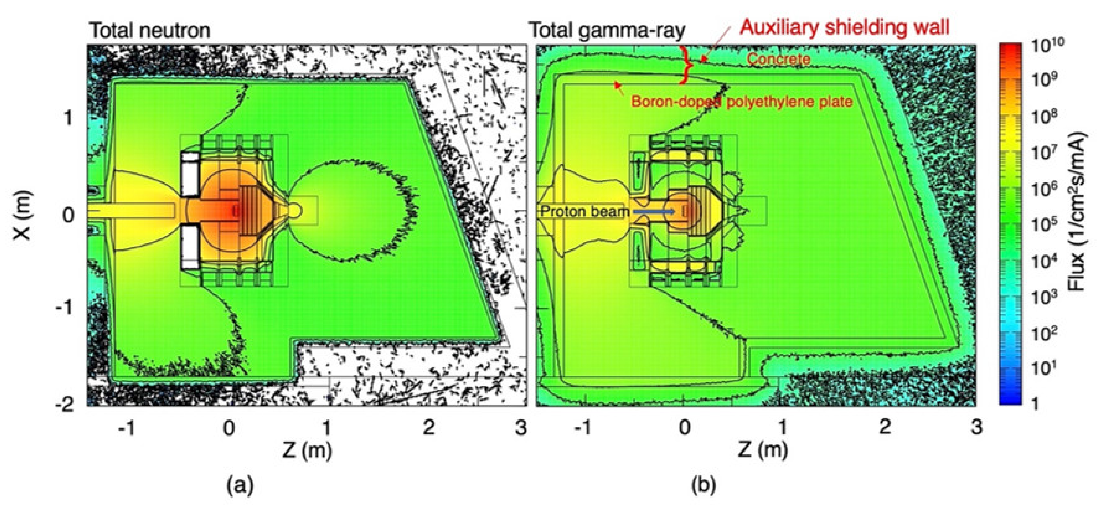
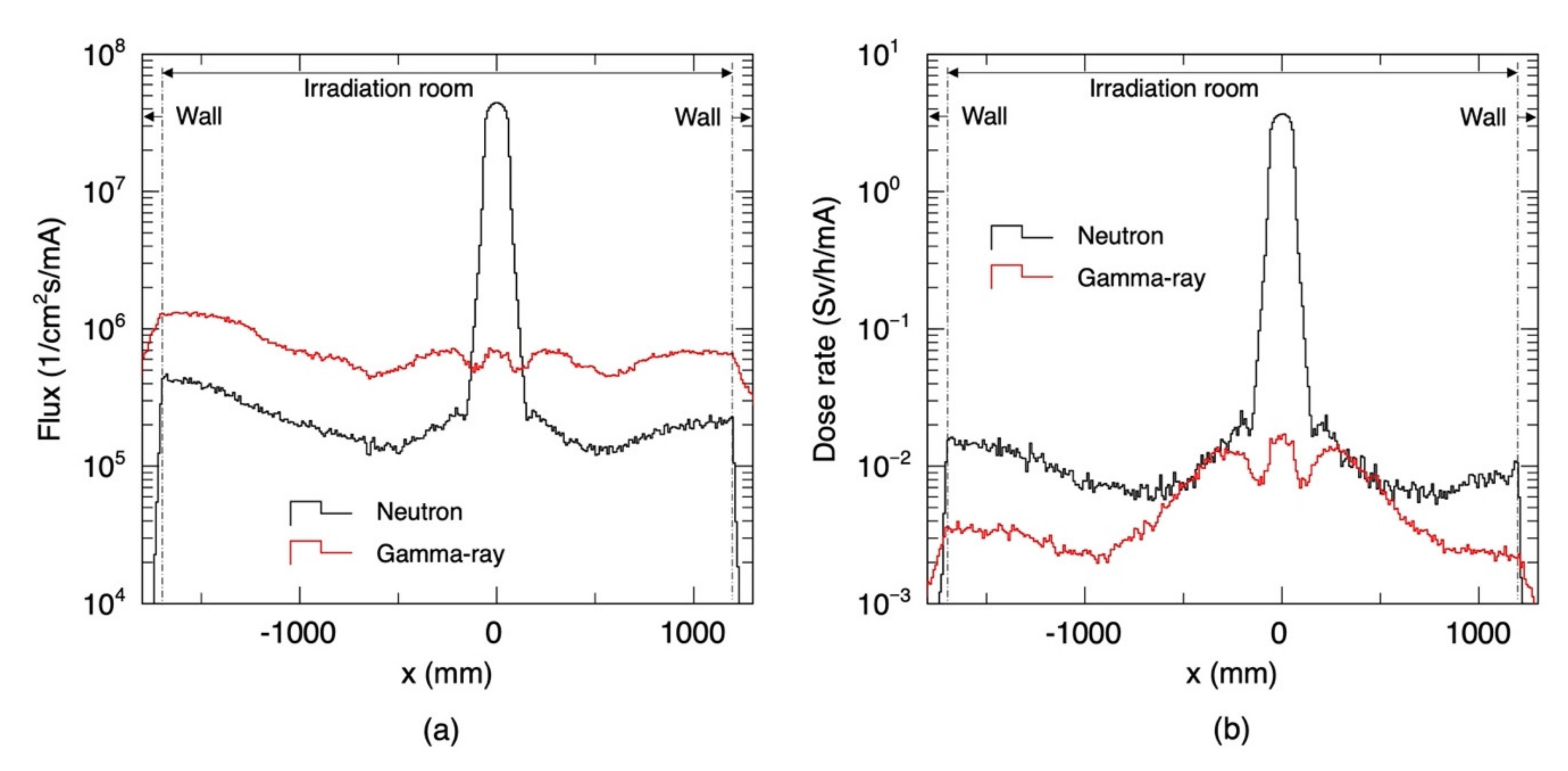
3.1. Radiation Field Inside the Irradiation Room
3.2. Radiation Field at the BSA Outlet and the Vicinity
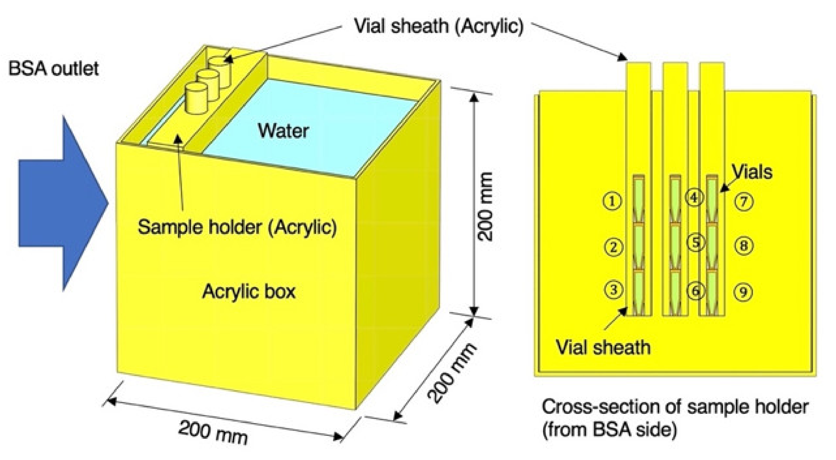
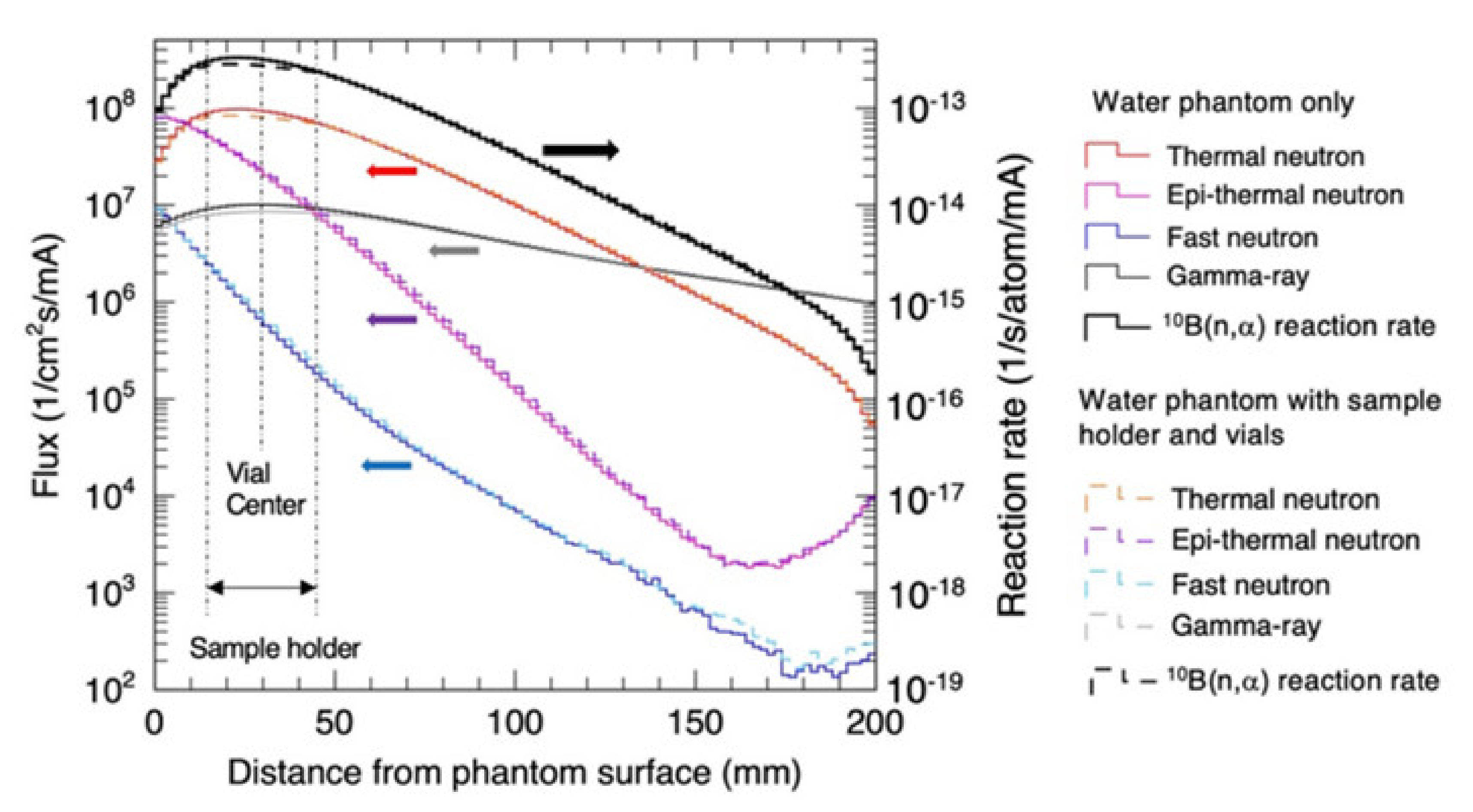
3.3. Radiation Field in the Water Phantom and Vials
4. Discussion
5. Conclusions
Author Contributions
Funding
Informed Consent Statement
Data Availability Statement
Acknowledgments
Conflicts of Interest
References
- Burian, J.; Marek, M.; Rataj, J.; Flibor, S. Current Status of Neutron Capture Therapy (IAEA-TECDOC-1223); International Atomic Energy Agency: Vienna, Austria, 2001. [Google Scholar]
- Farr, L.E.; Sweet, W.H.; Robertson, J.S.; Foster, C.G.; Locksley, H.B.; Suntherland, D.L.; Mendelsohn, M.L.; Stickly, E.E. Neutron Capture Therapy with Boron in the Treatment of Glioblastoma Multiforme. Am. J. Roentgenol. 1954, 71, 279–293. [Google Scholar]
- Bavarnegin, E.; Kasesaza, Y.; Wagner, F.M. Neutron beams implemented at nuclear research reactors for BNCT. J. Instrum. 2017, 12, P05005. [Google Scholar] [CrossRef] [Green Version]
- Sakurai, Y.; Tanaka, H.; Takata, T.; Fujimoto, N.; Suzuki, M.; Masunaga, S.; Kinashi, Y.; Kondo, N.; Narabayashi, M.; Nakagawa, Y.; et al. Advances in boron neutron capture therapy (BNCT) at kyoto university—From reactor-based BNCT to accelerator-based BNCT. J. Korean Phys. Soc. 2015, 67, 76–81. [Google Scholar] [CrossRef] [Green Version]
- Kasatov, D.; Koshkarev, A.; Kuznetsov, A.; Makarov, A.; Ostreinov, Y.; Shchudlo, I.; Sorokin, I.; Sycheva, T.; Taskaev, S.; Zaidi, L. The accelerator neutron source for boron neutron capture therapy. J Phys. Conf. Ser. 2016, 769, 12064. [Google Scholar] [CrossRef] [Green Version]
- Tanaka, H.; Sakuraia, Y.; Suzuki, M.; Masunaga, S.; Kinashi, Y.; Kashino, G.; Liu, Y.; Mitsumoto, T.; Yajima, S.; Tsutsui, T.; et al. Characteristics comparison between a cyclotron-based neutron source and KUR-HWNIF for boron neutron capture therapy. Nucl. Instr. Meth. Phys. Res. B 2009, 267, 1970–1977. [Google Scholar] [CrossRef]
- Kumada, H.; Naito, F.; Hasegawa, K.; Kobayashi, H.; Kurihara, T.; Takada, K.; Onishi, T.; Sakurai, H.; Matsuura, A.; Sakae, T. Development of LINAC-based neutron source for boron neutron capture therapy in University of Tsukuba. Plasma Fusion Res. 2018, 13, 24006006. [Google Scholar] [CrossRef] [Green Version]
- Kiyanagi, Y. Accelerator-based neutron source for boron neutron capture therapy. Ther. Radiol. Oncol. 2018, 2, 55. [Google Scholar] [CrossRef]
- Uritani, A.; Menjo, Y.; Watanabe, K.; Yamazaki, A.; Kiyanagi, Y.; Tsuchida, K. Design of Beam Shaping Assembly for an Accelerator-driven BNCT System in Nagoya University. In Proceedings of the International Conference on Neutron Optics (NOP2017), Nagoya, Japan, 21 June 2017. [Google Scholar]
- Sato, K.; Uritani, A.; Watanabe, K.; Yoshihashi, S.; Yamazaki, A.; Kiyanagi, Y.; Tsuchida, K. Improved Design of the Exit of a Beam Shaping Assembly for an Accelerator-Driven BNCT System in Nagoya University. In Proceedings of the International Conference on Neutron Optics (NOP2017), Nagoya, Japan, 21 June 2017. [Google Scholar]
- Watanabe, K.; Yoshihashi, S.; Ishikawa, A.; Honda, S.; Yamazaki, A.; Tsurita, Y.; Uritani, A.; Tsuchida, K.; Kiyanagi, Y. First experimental verification of the neutron field of Nagoya University Accelerator-driven neutron source for boron neutron capture therapy. Appl. Rad. Isotopes 2021, 168, 109553. [Google Scholar] [CrossRef] [PubMed]
- Dynamitron E-Beam Accelerator. Available online: https://www.iba-industrial.com/dynamitron-e-beam-accelerator-0/ (accessed on 16 May 2022).
- Sato, T.; Iwamoto, Y.; Hashimoto, S.; Tatsuhiko Ogawa, T.; Furuta, T.; Abe, S.; Kai, T.; Tsai, P.E.; Matsuda, N.; Iwase, H.; et al. Features of Particle and Heavy Ion Transport Code System (PHITS) version 3.02. J. Nucl. Sci. Technol. 2018, 55, 684–690. [Google Scholar] [CrossRef] [Green Version]
- Hashimoto, Y.; Hiraga, F.; Kiyanagi, Y. Effects of Proton Energy on Optimal Moderator System and Neutron-induced Radioactivity of Compact Accelerator-driven 9Be(p,n) Neutron Sources for BNCT. Phys. Procedia 2014, 60, 332–340. [Google Scholar] [CrossRef] [Green Version]
- Shibata, K.; Iwamoto, O.; Nakagawa, T.; Iwamoto, N.; Ichihara, A.; Kunieda, S.; Chiba, S.; Furutaka, K.; Otuka, N.; Ohsawa, T.; et al. JENDL-4.0: A new library for nuclear science and engineering. J. Nucl. Sci. Technol. 2011, 48, 1–30. [Google Scholar] [CrossRef]
- Chadwick, M.B.; Obložinský, M.; Herman, P.; Greene, N.M.; McKnight, R.D.; Smith, D.L.; Young, P.G.; MacFarlane, R.E.; Hale, G.M.; Frankle, S.C.; et al. ENDF/B-VII.0: Next Generation Evaluated Nuclear Data Library for Nuclear Science and Technology. Nucl. Data Sheets 2006, 107, 2931. [Google Scholar] [CrossRef] [Green Version]
- Nishitani, T.; Tanagami, Y.; Yoshihashi, S.; Tsuchida, K.; Yamazaki, A.; Uritani, A. Neutron yield calculation of p-Li thick target by using PHITS with JENDL-4.0/HE and ENDF/B-VII for BNCT application. J. Nucl. Sci. Technol. 2022, 59, 605–613. [Google Scholar] [CrossRef]
- ICRP. The 1990 Recommendation of International Commission on Radiological Protection. Publication 60. Available online: https://www.icrp.org/publication.asp?id=icrp%20publication%2060 (accessed on 11 April 2022).
- Hiraga, F.; Ooieb, T. Synergistic effects of fast-neutron dose per epithermal neutron and 10B concentration on relative-biological-effectiveness dose for accelerator-based boron neutron capture therapy. Appl. Rad. Isot. 2019, 144, 1–4. [Google Scholar] [CrossRef] [PubMed]
- Ishikawa, A.; Yamazaki, A.; Watanabe, K.; Yoshihashi, S.; Uritani, A.; Sakurai, Y.; Tanaka, H.; Ogawara, R.; Suga, M.; Hamano, T. Development of Optical-fiber-based Neutron Detector Using Li-glass Scintillator for an Intense Neutron Field. Sens. Mater. 2020, 32, 1489–1495. [Google Scholar] [CrossRef] [Green Version]
- Kumada, H.; Takada, K. Treatment planning system and patient positioning for boron neutron capture therapy. Ther. Radiol. Oncol. 2018, 2, 50. [Google Scholar] [CrossRef]


| Parameters | PHITS Calculation | IAEA Recommendation |
|---|---|---|
| Epithermal neutron flux (1/cm2/s) ϕepi | (8.04 ± 0.03) × 108 (at 15 mA) | ≥1 × 10⁹ |
| Fast neutron flux (1/cm2/s) ϕf | (1.42 ± 0.01) × 108 (at 15 mA) | No recommendation |
| Thermal neutron flux (1/cm2/s) ϕth | (5.31 ± 0.53) × 106 (at 15 mA) | No recommendation |
| Thermal neutron flux ratio ϕth/ϕepi | 0.0066 ± 0.0004 | ≤0.05 |
| Ratio of Epithermal neutron current to Epithermal neutron flux Cepi/ϕepi | 0.726 ± 0.006 | ≥0.7 |
| Fast neutron dose per epithermal neutron flux (Gy cm2) Df/ϕepi | (5.28 ± 0.08) × 10−13 | ≤2 × 10⁻¹³ |
| Gamma-ray dose per epithermal neutron flux (Gy cm2) Dg/ϕepi | (1.00 ± 0.19) × 10−13 | ≤2 × 10⁻¹³ |
| Vial number | #1 | #4 | #7 |
| Thermal neutron flux (×107/cm2 s/mA) | 6.49 ± 0.01 | 7.17 ± 0.01 | 6.49 ± 0.01 |
| Fast neutron flux (×106/cm2 s/mA) | 6.20 ± 0.02 | 7.36 ± 0.02 | 6.40 ± 0.02 |
| Gamma-ray flux (×106/cm2 s/mA) | 7.37 ± 0.01 | 7.87 ± 0.01 | 7.41 ± 0.01 |
| Vial number | #2 | #5 | #8 |
| Thermal neutron flux (× 107/cm2 s/mA) | 7.77 ± 0.01 | 8.49 ± 0.01 | 7.75 ± 0.01 |
| Fast neutron flux (×106/cm2 s/mA) | 6.89 ± 0.02 | 7.89 ± 0.02 | 7.05 ± 0.02 |
| Gamma-ray flux (×106/cm2 s/mA) | 8.40 ± 0.01 | 9.01 ± 0.01 | 8.82 ± 0.01 |
| Vial number | #3 | #6 | #9 |
| Thermal neutron flux (×107/cm2 s/mA) | 6.69 ± 0.01 | 7.38 ± 0.01 | 6.71 ± 0.01 |
| Fast neutron flux (×106/cm2 s/mA) | 6.23 ± 0.02 | 7.30 ± 0.02 | 6.38 ± 0.02 |
| Gamma-ray flux (×106/cm2 s/mA) | 7.52 ± 0.01 | 8.09 ± 0.01 | 7.54 ± 0.01 |
Publisher’s Note: MDPI stays neutral with regard to jurisdictional claims in published maps and institutional affiliations. |
© 2022 by the authors. Licensee MDPI, Basel, Switzerland. This article is an open access article distributed under the terms and conditions of the Creative Commons Attribution (CC BY) license (https://creativecommons.org/licenses/by/4.0/).
Share and Cite
Nishitani, T.; Yoshihashi, S.; Tanagami, Y.; Tsuchida, K.; Honda, S.; Yamazaki, A.; Watanabe, K.; Kiyanagi, Y.; Uritani, A. Neutronics Analyses of the Radiation Field at the Accelerator-Based Neutron Source of Nagoya University for the BNCT Study. J. Nucl. Eng. 2022, 3, 222-232. https://doi.org/10.3390/jne3030012
Nishitani T, Yoshihashi S, Tanagami Y, Tsuchida K, Honda S, Yamazaki A, Watanabe K, Kiyanagi Y, Uritani A. Neutronics Analyses of the Radiation Field at the Accelerator-Based Neutron Source of Nagoya University for the BNCT Study. Journal of Nuclear Engineering. 2022; 3(3):222-232. https://doi.org/10.3390/jne3030012
Chicago/Turabian StyleNishitani, Takeo, Sachiko Yoshihashi, Yuuki Tanagami, Kazuki Tsuchida, Shogo Honda, Atsushi Yamazaki, Kenichi Watanabe, Yoshiaki Kiyanagi, and Akira Uritani. 2022. "Neutronics Analyses of the Radiation Field at the Accelerator-Based Neutron Source of Nagoya University for the BNCT Study" Journal of Nuclear Engineering 3, no. 3: 222-232. https://doi.org/10.3390/jne3030012