1. Introduction
Molten-salt reactors (MSRs) are characterized by either the coolant or both coolant and fuel consisting of molten salts, typically fluorides or chlorides. From the safety point of view, the MSRs differ significantly from the light water reactors, having many features which make the use of the traditional classification of safety barriers, core damage states, and accident sequences of little use when assessing the safety of these reactors. Severe accidents, for example, have been typically characterized as showing a considerable degree of core damage and a fraction of the core in a molten state. In many MSR designs using a molten fuel, this classification cannot be applied. The ultimate safety goal, however, remains the same in all nuclear reactors: to ensure reactor operation without an unplanned release of radioactivity so as to threaten humans or the environment. The absence of a fuel cladding and the presence of a large fraction of radioactive material not only in the core but also in auxiliary systems, such as an off-gas system and fuel treatment facility, make MSR distinctly different from light water reactors when regarding the confinement of radioactivity.
As in any nuclear reactor, also in MSR, the formation and transport of radioactive vapors and aerosol particles play a key role in the source term evaluation during severe accidents. In a typical Light Water Reactor (LWR), most of the fission products (FPs) transported in the reactor coolant system will be in particulate form, with the exception of the noble gases Xe and Kr, and iodine, which can form molecular I
2 or organic iodine compounds that exist in the vapor phase in the containment building (see References [
1,
2]). The behavior of fission product compounds depends, for example, on the concentration of the different species and on the thermal–hydraulic conditions, such as temperature and pressure, of the reactor coolant system and the containment. Less information is available on the forms of fission products released in an accident situation from more advanced reactor types, e.g., Gen IV reactors; however, the expected form of transport would in all reactor types be as an aerosol with varying fractions of gas-phase compounds depending on the gas composition and temperature. In an MSR, the fuel can be dissolved in the salt that also acts as the reactor coolant. Because of its different design principles compared to LWRs, the release of radioactive material in an accident in the MSR cannot be determined based solely on the knowledge of LWR accident source terms.
Only limited experimental data are available to support source term assessment from MSRs. In addition, a large number of different MSR designs and salt compositions make it difficult to apply data developed for one reactor type to another one. The Molten Salt Reactor Experiment [
3] showed that very small amounts of fission products were released from the reactor during operation of the reactor; however, accident conditions were not tested. In the absence of experimental data, analytical tools have been and still are developed to estimate the release of radioactive materials from MSRs under postulated accident conditions.
The European project “Simulation Models and Safety Assessment for Fluid-fuel Energy Reactors” (SAMOSAFER) aims at developing and demonstrating new safety barriers to control the behavior of molten-salt reactors in severe accidents [
4]. SAMOSAFER is a continuation of various activities undertaken in Europe to investigate and develop an MSR. Those activities started in the early 2000s with a concept derived from the American Molt Salt Experiment. The activities were continued in the European EVOL and SAMOFAR projects [
5,
6]. In SAMOSAFER, new simulation models and tools are developed and validated by experiments. The reactor under investigation in SAMOSAFER is designed with a fast neutron spectrum and will be able to be operated in the full range from breeder to burner reactor. This flexibility is facilitated by the fact that the fuel-salt composition can easily be adapted during reactor operation without manufacturing solid fuel elements. During reactor operation, a fraction of the salt is continuously diverted to an ex-core salt clean-up unit to extract lanthanides and actinides [
4].
In this work, evaporation of fission products and salt compounds during a hypothetical MSR accident in which the fuel salt is drained from the fuel casing onto the floor of a confinement is analyzed. The confinement is under a nitrogen atmosphere, and the fission products and salt material are evaporated from the surface of a molten salt pool, which is formed on the confinement floor. In the absence of a detailed confinement design, a generic very much simplified confinement geometry is assumed. Thereby the conditions of the present investigation can be considered as generic bounding conditions in which the detailed designs of, e.g., storage tanks, are not considered. Inclusion of the detailed geometries, once available, is expected to affect the release of fission products and salt materials. In addition to the release of radioactive materials from the fuel salt, the formation of aerosol particles in the modeled confinement is investigated.
2. Materials and Methods
For the analysis of the fission product material and fission product evaporation, as well as aerosol formation, the integral severe accident analysis code MELCOR [
7] was used together with a thermodynamic solver GEMS [
8], using HERACLES database [
9].
2.1. cGEMS
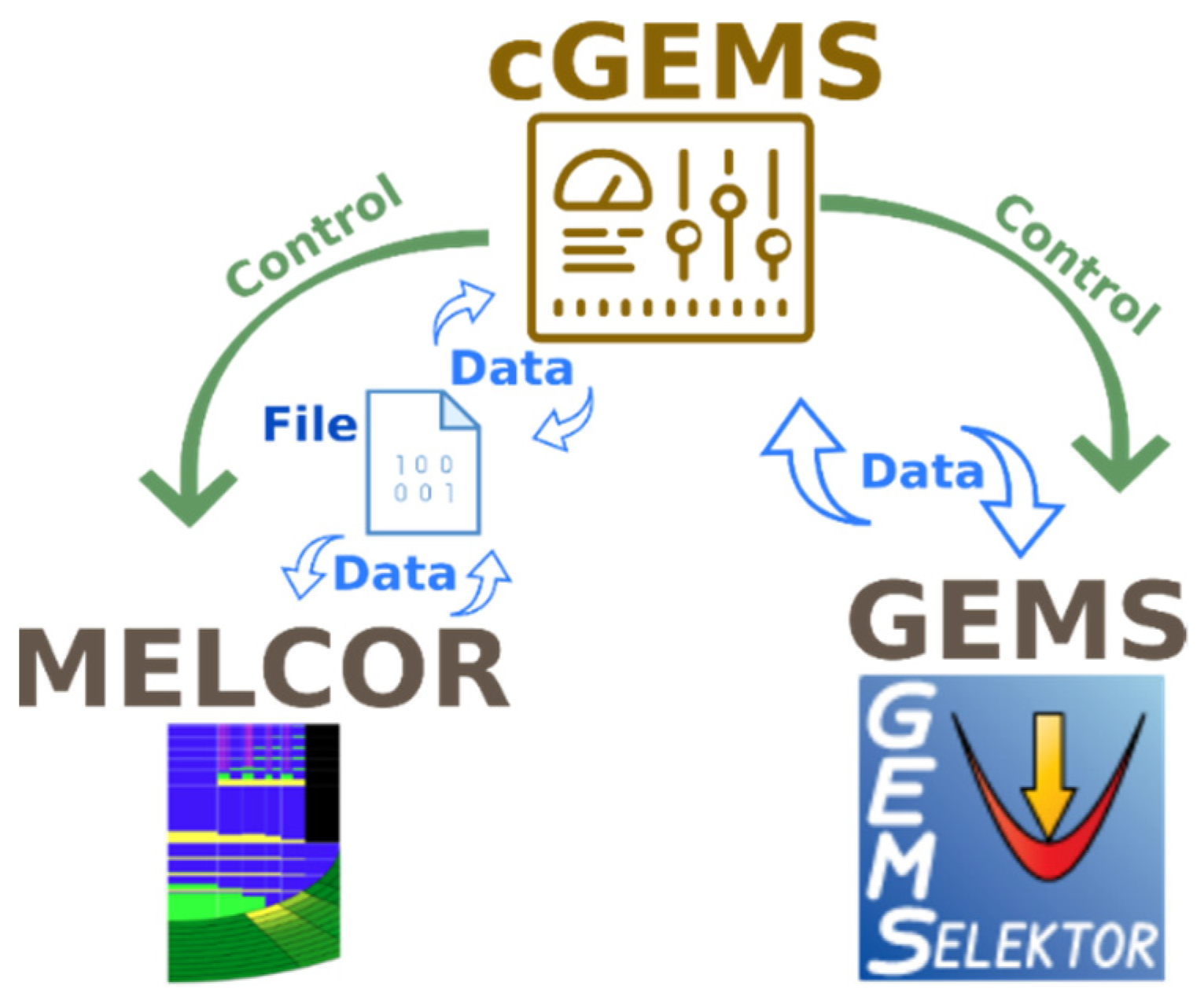
The MELCOR and GEMS codes were coupled by using a code called cGEMS, which was developed at PSI [
10]. Overall, cGEMS serves as an interface between the GEMS and MELCOR and facilitates an exchange of information between both codes. Moreover, cGEMS can call both MELCOR and GEMS depending on the situation, and it has a controlling function in the simulation process.
Since MELCOR is a commercial package and PSI has no access to the source code, the coupling between MELCOR and GEMS was made through an external file system. This means that cGEMS supplies information to MELCOR through external input files. To pass the information, cGEMS has to restart MELCOR every time step with a new input file with the updated information. A continuous restart of MELCOR with intermediate calculations with GEMS leads to increased calculation time in comparison with stand-alone MELCOR calculations. At the same time, cGEMS has direct access to the GEMS code through its Application-Programming Interface (API), which simplifies the data exchange in GEMS.
The general idea of the simulation flow is demonstrated by using a diagram in which the process is split into a number of different steps managed by the cGEMS code (
Figure 1) [
11]:
Run the MELCOR simulation for a preset time step (200 s in this study);
Collect data from MELCOR containing an elemental composition of the fission products in the fuel, as well as the temperature of the fuel salt, and pass them to GEMS for thermodynamic calculations;
Run GEMS thermodynamic simulation;
Collect and prepare GEMS results and pass the vapor pressure of the simulated species in the salt mixture to MELCOR, using a new input file;
Repeat the cycle.
2.2. HERACLES Database
A backbone of any thermodynamic modeling is a reliable and consistent database that contains the underlying thermodynamic data for the necessary chemical species, as well as parameters for different pair-wise (e.g., energy of the pair Li-Th in the presence of F), and higher orders (e.g., energy of the complex Li-Th-U in the presence of F) interactions. These interaction parameters describe deviations of mixing behavior from the ideal, random mixing in the gaseous, liquid, and solid phase. At PSI, a dedicated thermodynamic database, HERACLES, for nuclear-field-related research has been developed and is being maintained and constantly extended [
9]. Originally, the HERACLES database was compiled to support modeling of uranium and fission products speciation during pyro-reprocessing of spent nuclear fuel. For the work in the field of MSR, the HERACLES database was extended with relevant fluoride and chloride species. The HERACLES database covers molar thermodynamic properties (formation enthalpy and Gibbs energy, standard entropy, temperature dependence of heat capacity, etc.) of solid, liquid (melt), and gaseous compounds of actinides, fission products, and minor actinides in the temperature range of up to 3000 K, covering the majority of the elements of interest. In its current state, the HERACLES database covers metals, actinides, fission products, gases, and salts with more than 600 condensed compounds and 400 gaseous species.
For this work, the HERACLES database was updated with data relevant to MSRs. The data were collected from published sources. The collected data were validated against available experimental data on the melting and boiling points for each particular compound to ensure the accuracy of the underlying standard thermodynamic data.
In case there was a noticeable deviation of the calculated values from the experimental data, e.g., phase equilibria speciation, the underlying thermodynamic data were corrected to reproduce the experimental data. The data correction involved the adjustment of the underlying formation enthalpies and standard entropies of the species. All the corrections were performed by taking into account the available literature information on thermodynamic properties of a particular compound. In the majority of cases, the corrections to the underlying thermodynamic data did not exceed the uncertainty of the original thermodynamic data (±2.0 kJ/mol for a formation enthalpy value and ±5 J/(mol K) for a standard entropy value). The corrections concerned only complex intermediate compounds, such as Li
7Th
6F
31 or LiTh
4F
17, for which no reliable experimental data are available or the available data are a result of some type of an assessment [
1]. Such an approach to thermodynamic data collection and validation attempted to ensure the quality of thermodynamic data in the HERACLES database.
Besides the update of the standard thermodynamic data of the pure species in the HERACLES database, significant efforts were dedicated to the improvement of the description of the mixing effects in the solution (liquid and solid) phases and behavior of multicomponent systems. The mixing effects define a deviation of a real system-mixing behavior from a random, ideal mixing behavior and can be described in terms of excess Gibbs energy, which can be expressed by one of many developed mixing models. The information on binary-excess interactions, in turn, allows for modeling of multicomponent mixtures under the assumption that the contribution from ternary and higher-order interactions to the total Gibbs energy of a multicomponent system is negligible. Such an approach has proven to provide an accurate description of the multicomponent systems [
11,
12,
13,
14,
15,
16].
The selected mixing model in the HERACLES database is the Redlich–Kister mixing model Equation (1) [
17], which was chosen due to its flexibility and ability to describe quite complex excess Gibbs energy curves for binary systems.
where
are the dimensionless fitting parameters of the model;
and
are the mole fractions of the components of the solution,
i and
j; and
n is the maximum power in the series that defines the number of interaction parameters for the pair of components
i and
j.
To properly describe multicomponent systems, the available experimental data on phase equilibria and excess Gibbs energy for binary systems were collected [
13,
14,
15,
16,
18,
19] and, further, a fit of the calculated phase equilibria to the experimental data was performed by adjusting the parameters,
, of a selected mixing model for every binary system. The list of all the binary interactions for a liquid phase and a list of all the relevant binary solid solutions are presented in
Table 1.
However, it should be noted that there is information on binary interactions only for a number of systems, mostly involving the base salt components [
13,
14,
16,
18,
20]. There is no information for every possible binary, or higher-order, interaction, what can be explained by the exponentially growing number of all possible binary and higher-order interactions with increasing number of elements in such systems.
2.3. Evaporation and Fission Product Transport Model
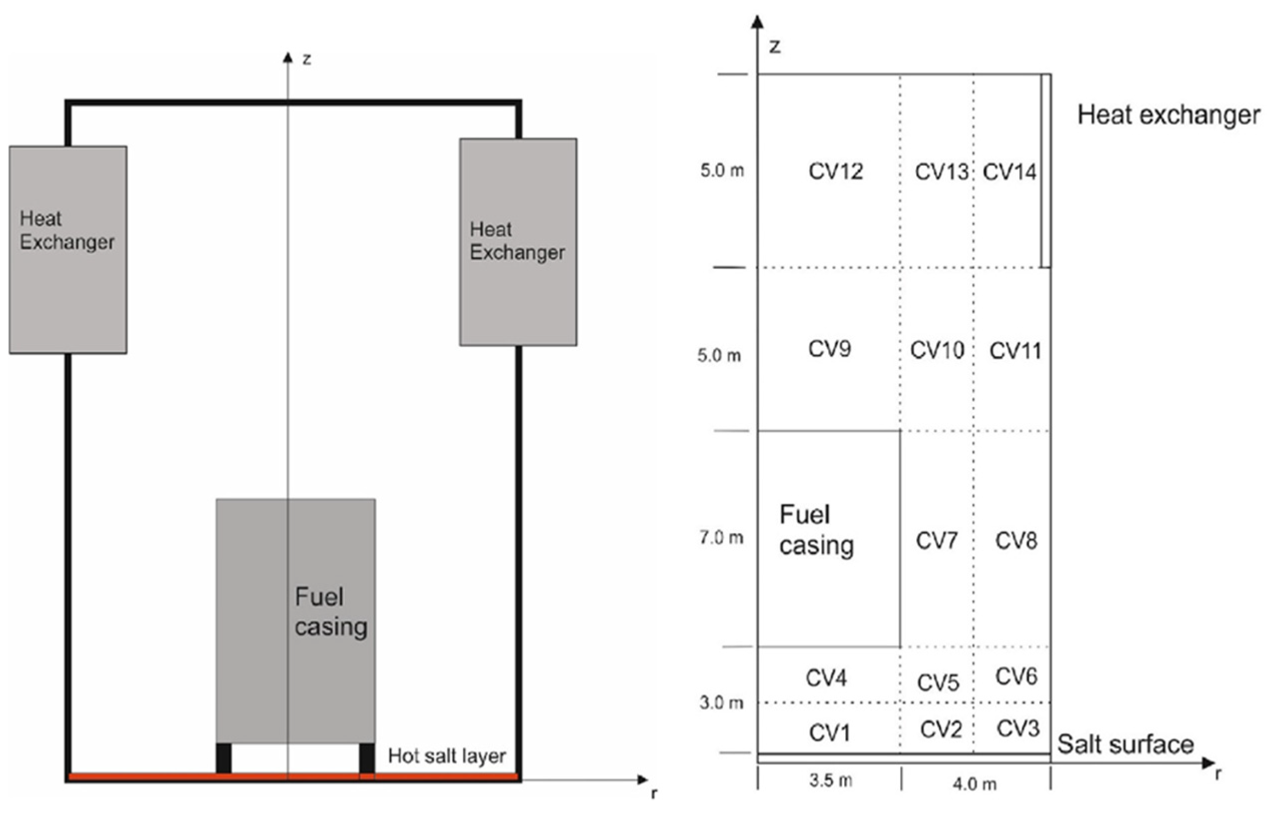
In the input model for this work, the confinement is a generic simplified design used in earlier investigations [
12]. It is modeled as a cylindrical container with a salt layer at the bottom surface (
Figure 2). In the middle of the confinement is a fuel casing from which the salt was drained in accident conditions and was then uniformly distributed at the bottom of the confinement. A gas–gas heat exchanger encircles the confinement at 15 m above the floor level. The heat exchanger surface area is approximately 235 m
2. The initial confinement atmosphere consists of nitrogen at atmospheric pressure.
The MELCOR model of the confinement is divided into 14 control volumes (CVs) which are connected with flow paths allowing convective heat transfer and transport of the evaporated material (
Figure 2). Adiabatic temperature boundary conditions are set to all confinement boundary heat structures, except on the isothermal heat exchanger and salt surfaces. The hot salt and the colder heat exchanger induce natural convective flow in the container, driving the heat and mass transfer as modeled by MELCOR. Along with convection, heat conduction and thermal radiation are also considered in the MELCOR simulation in which the temperature of each control volume, and the heat transfer between the control volumes is calculated. For a more extensive description of the MELCOR input model and the evaporation modeling geometry, please refer to Reference [
12].
The salt layer at the bottom of the confinement is described by a heat structure in the MELCOR input deck. At simulation time t = 0 s, the whole core is assumed to be released onto the containment floor. The salt surface heating was started at a rate 6 K/min, simulating the salt heat-up due to the decay heat, which is approximately 129 MW, immediately after the reactor shutdown. The initial temperature of the salt, all confinement surfaces, and the atmosphere was set to 800 K. The temperature increase of the gas atmosphere in the confinement due to heat transfer from the salt was calculated by MELCOR. The slow heating rate allowed the changes of the evaporation process in different fuel temperatures to be clearly observed. The gas–gas heat-exchanger temperature was increased from 300 K with the same heating rate as the salt, until it reached the temperature of 500 K, after which it was kept constant. At each simulation time step, the evaporation rate of FPs and salt components from the salt surface to the bottom CVs 1–3 was calculated by using the methodology described in Reference [
12].
After the release of the different salt species and fission-product species from the salt on the confinement floor, their evolution in the confinement atmosphere was analyzed with MELCOR. For the aerosol formation and transport calculations, saturation vapor pressures of the evaporated compounds were calculated by using GEMS and added to the MELCOR input, as described in Reference [
12]. Aerosol particle density was assumed to be 4000 kg/m
3, which is approximately an average of the densities of species considered in the evaporation simulations.
2.4. Simulation Matrix
To simulate the evaporation of the fission products and salt compounds, the speciation of the different elements in the salt was calculated. This was performed by using the mass of different elements calculated by EQL0D as an input for the thermodynamic solver GEMS [
7]. EQL0D is a Serpent 2-based procedure developed for both equilibrium and finite-time burn-up calculations in liquid-fueled molten-salt reactors.
The elements for the simulation were selected based on their abundance in the fuel salt, their possible radiotoxicity, and their availability in the updated HERACLES database. In a previous study, the evaporation of Li, Th, U, Cs, I, and F was investigated by using cGEMS [
12]. The list of chosen elements for the present study was extended to include the following elements: Zr, Np, Pu, U, Th, Sr, Ba, Cs, La, Ce, Nd, Li, and F. The composition of the salt layer on the confinement floor in the beginning of the calculation was obtained from the EQL0D simulation data [
21] and is shown in
Table 2.
In the beginning of this work, it was suspected that the evaporation behavior of fission products and salt material could be dependent on the fluorine concentration in the salt [
9]. Therefore, simulations were carried out by varying the fluorine concentration in the salt within ±1 mol% from the stoichiometric value. Thereby, three simulations were carried out, the “base case” with a stoichiometric fluorine concentration, “under-fluorinated case” with −1 mol% fluorine, and “over-fluorinated case” with +1 mol% fluorine in the salt. Such fluorine-sensitivity calculations allowed for an investigation of the effects of fluorine variation on the speciation of FPs.
3. Results
3.1. Release of Salt Material and Effect of Fluorine Concentration
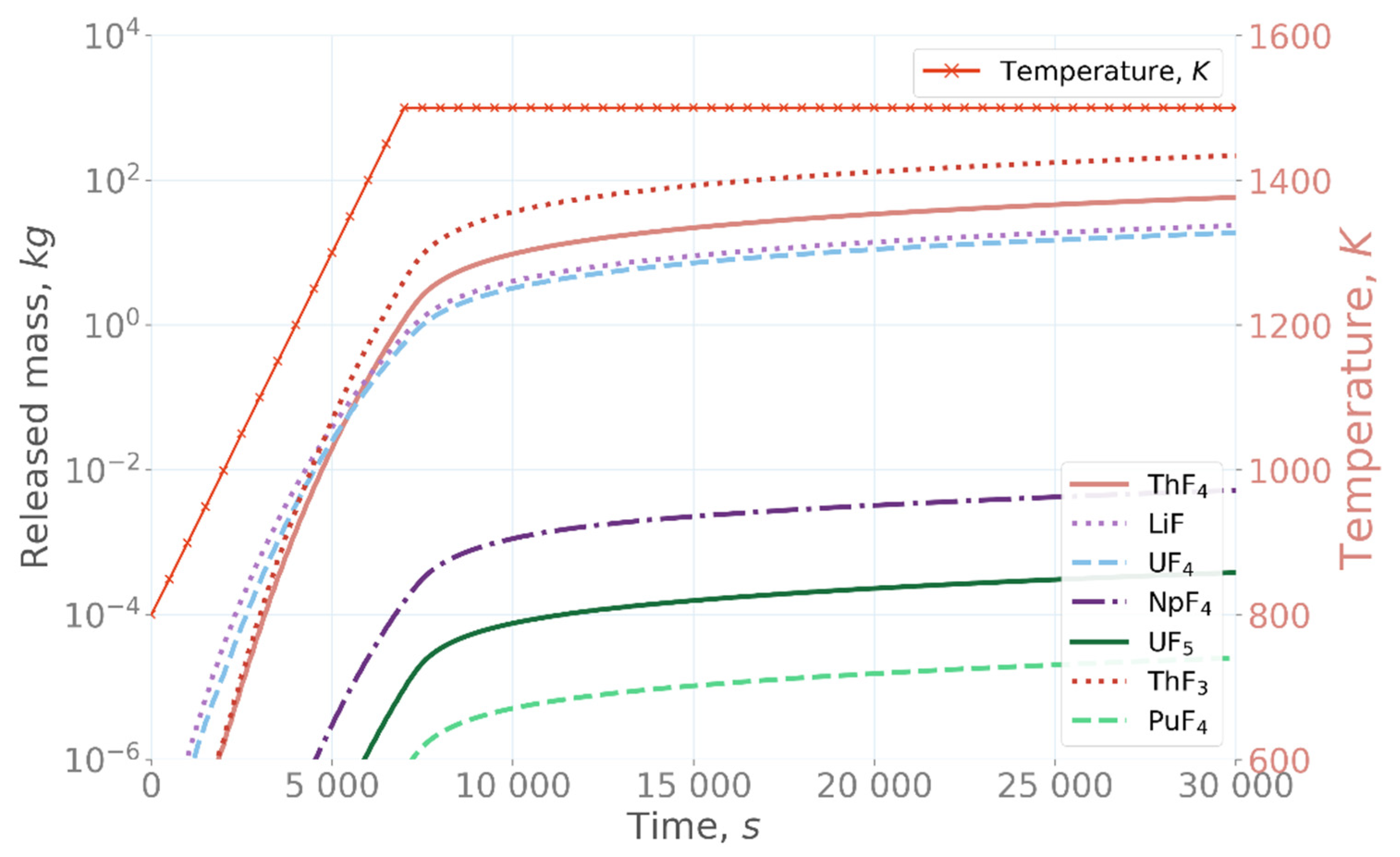
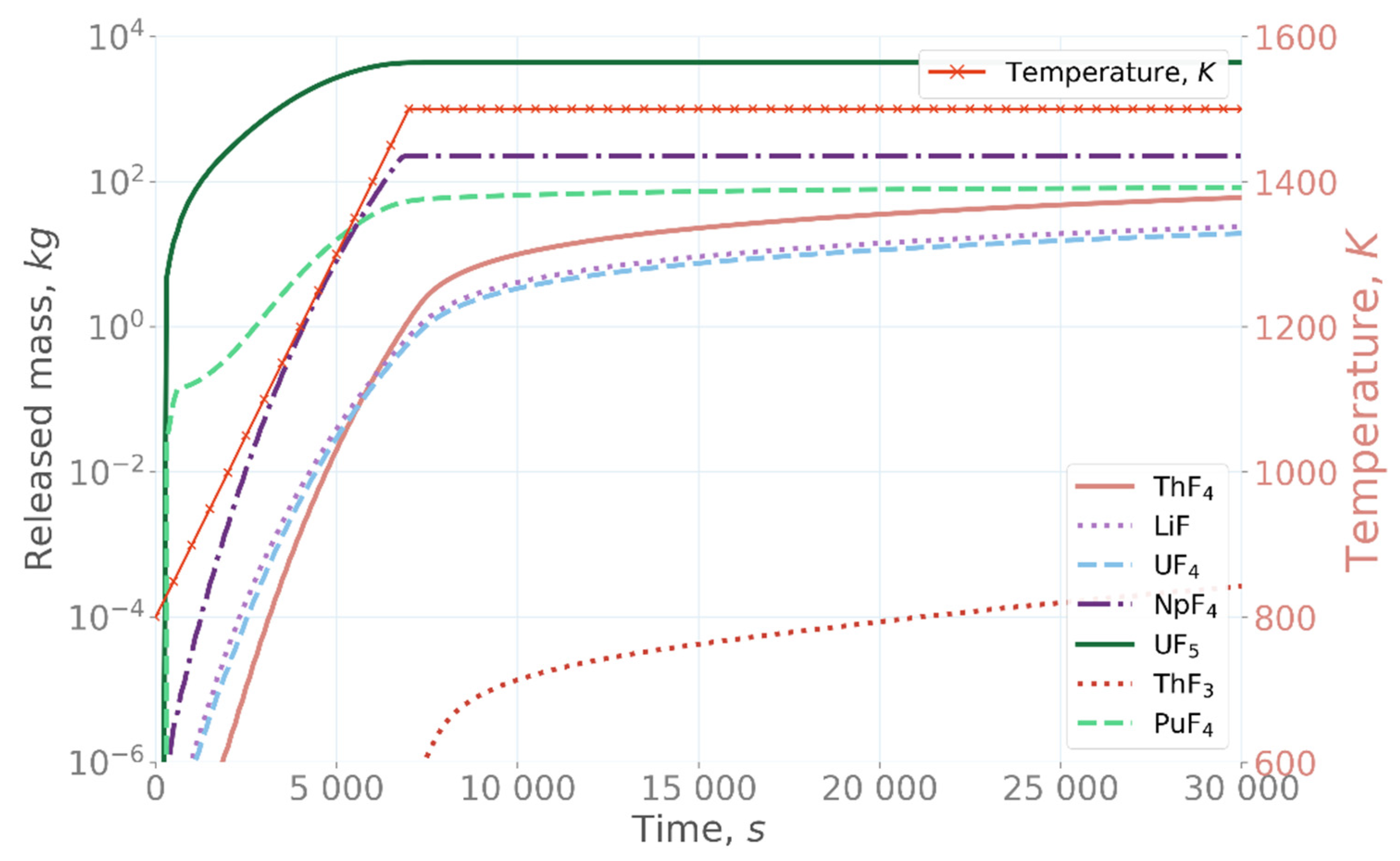
The simulations showed that significant amounts of salt materials and actinide species were released from the salt when the salt was heated up on the confinement floor (
Figure 3) [
22]. Of the investigated species, LiF, UF
4, and ThF
4 were seen to be most volatile, with more than 10 kg of each released after 15,000 s at 1500 K. Additionally, NpF
4 was shown to be relatively volatile, with approximately 6 kg released from the salt after 10,000 s. The apparent non-steady increase of the NpF
4, UF
5, and PuF
4 release at the beginning of the simulation was presumably caused by numerical instabilities in the GEMS simulation that did not appear at higher temperatures or in the simulations with different fluorine concentrations, as shown below. This behavior is the matter of future research.
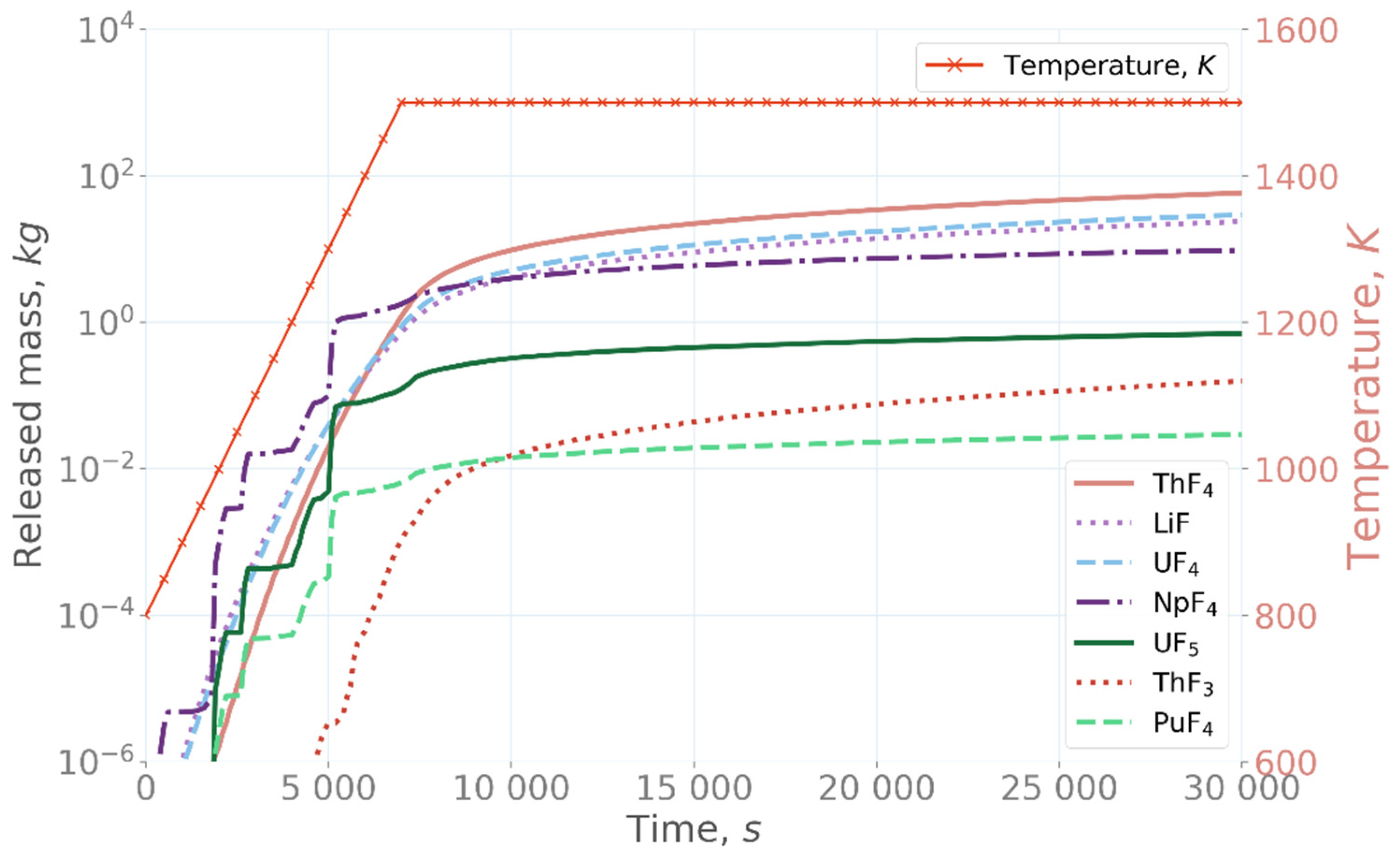
In the over-fluorinated case with 1% more fluorine in the salt than the stoichiometric concentration, the volatility of UF
5, NpF
4, and PuF
4 increased significantly, showing the highest releases, as can be seen in
Figure 4 [
22]. On the other hand, in the under-fluorinated case with 1% less fluorine than the stoichiometric concentration, the three compounds showing high release in the over-fluorinated simulation are significantly less volatile, and ThF
3 has become the most volatile species,
Figure 5 [
22]. These results demonstrate the significant effect of the fluorine concentration in the salt evaporation, as only a 1% change in the fluorine concentration affects the release of different compounds by orders of magnitude.
3.2. Release of Fission Products
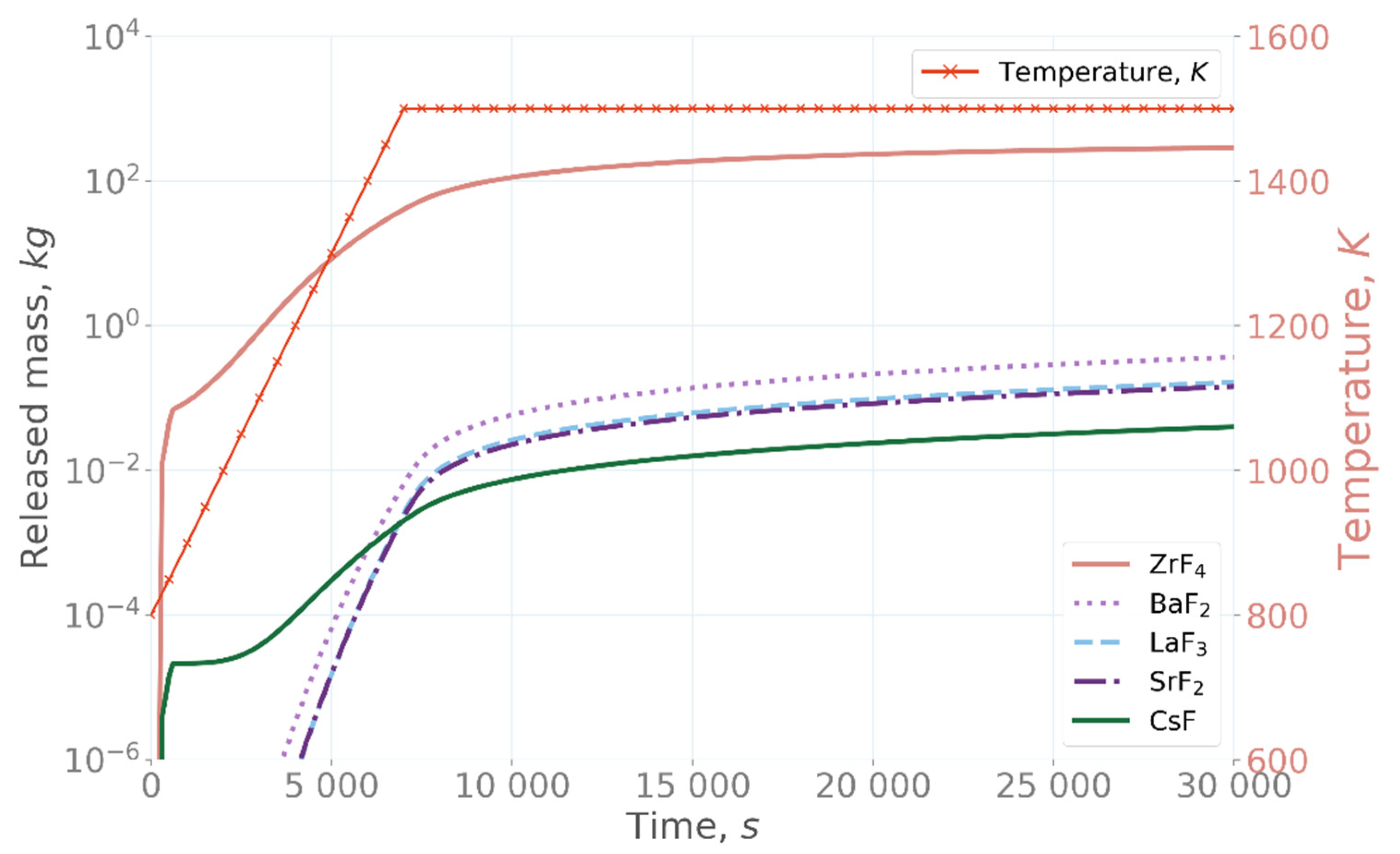
In all the simulations, ZrF
4 was the most volatile fission product species (
Figure 6). Over 100 kg was evaporated from the salt at 10,000 s in each of the simulations. The fission-product release results with the three different fluorine contents were very comparable, with only a minor difference in the early release of ZrF
4 and CsF, as it was slightly delayed in the under-fluorinated simulation. The results also show that CsF was the least volatile species of all the fission products which were used in the simulations.
3.3. Aerosol Formation
A fraction of the salt compounds and fission products form aerosol particles once released from the salt to the gas phase. The aerosol formation is caused by the gas temperature decrease from the fuel temperature to the gas temperature of the confinement atmosphere, and corresponding chemical reactions of the evaporated compounds. Nucleation was presumably followed by particle growth as a result of coagulation and heterogeneous condensation of the more volatile species on the nuclei formed by nucleation. The aerosol formation and growth in the confinement were simulated by using GEMS.
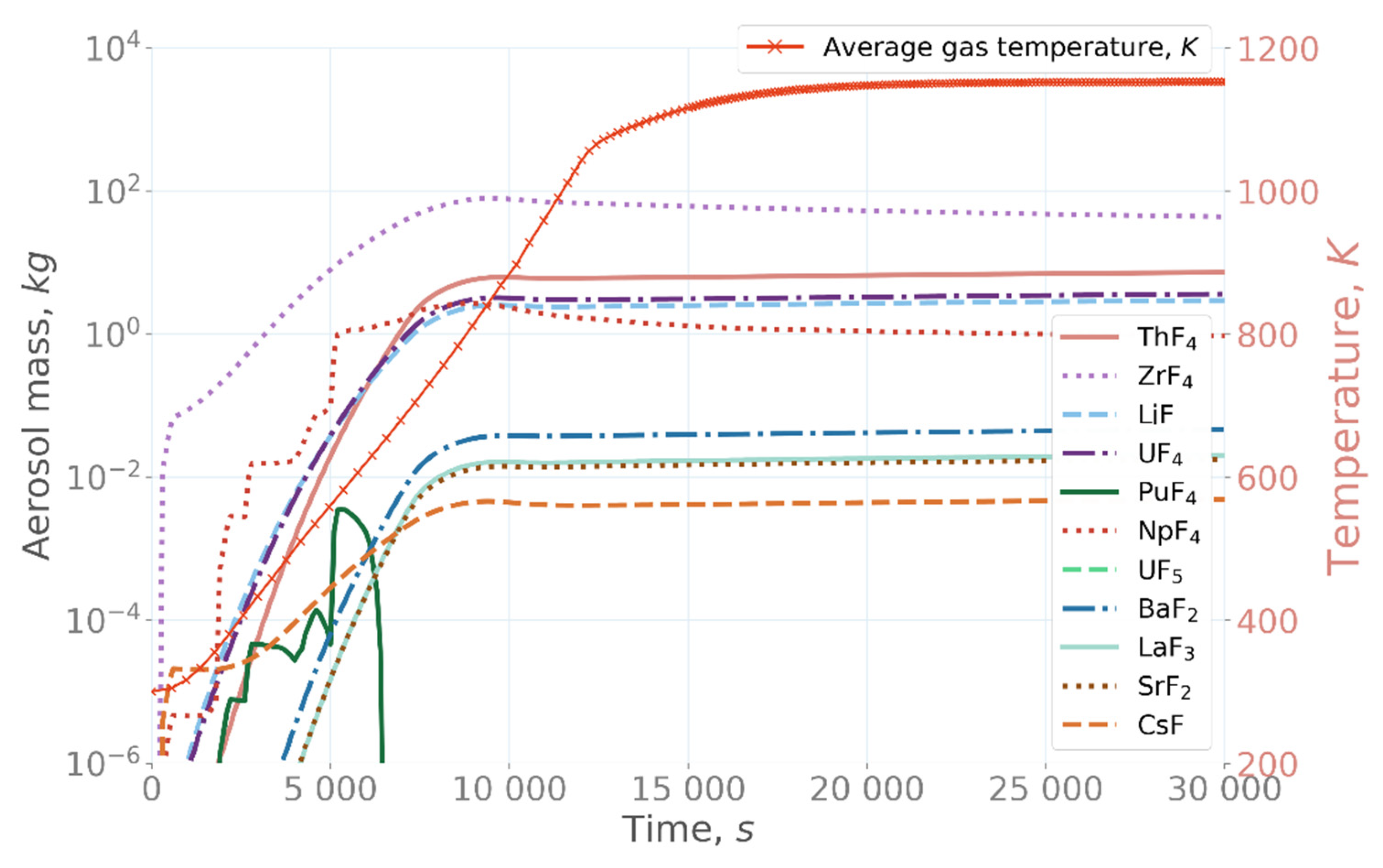
In the base case simulation, aerosol mostly comprised ZrF
4, with additionally significant amounts of ThF
4, LiF, UF
4, and NpF
4 (
Figure 7) [
22]. Maximally, approximately 79 kg of ZrF
4 existed air-borne in the confinement at 9500 s. Moreover, approximately 1–6 kg of LiF, UF
4, ThF
4, and NpF
4 each could be found as an aerosol after 10,000 s.
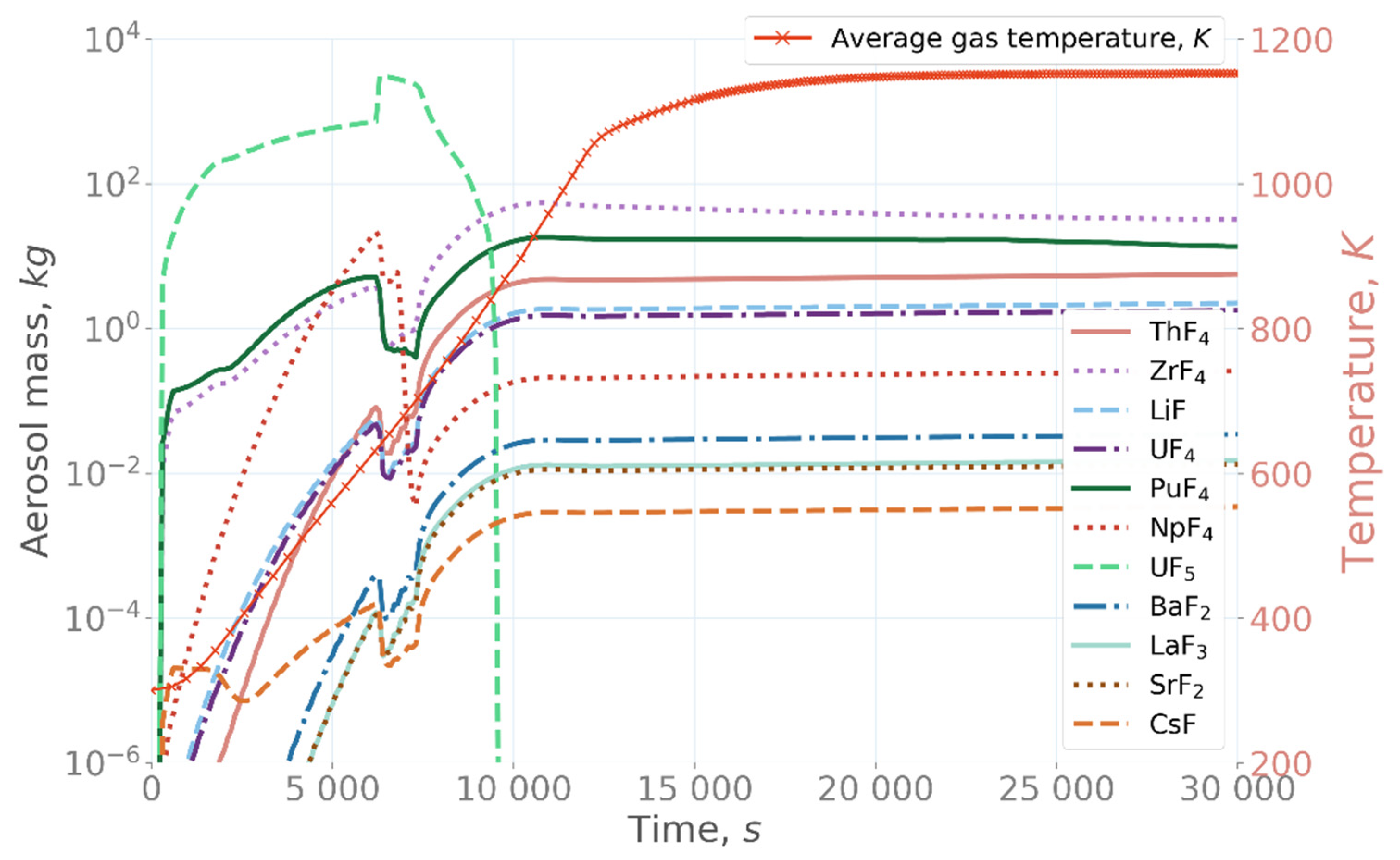
In the over-fluorinated simulation case (
Figure 8) [
22], UF
5 was the dominating species in the aerosol until approximately 9000 s. After its release from the salt, UF
5 started to form aerosol particles, due to its rapidly increasing mass concentration in the confinement. After 7000 s, when the maximum temperature of the salt was reached and, consequently, UF
5 release had stopped, UF
5 concentration in the aerosol particles started to decrease due to vaporization of UF
5 from the aerosol back to vapor phase, due to its high vapor pressure. UF
5 was released completely back to the vapor phase from the aerosol particles after 9000 s. After that, the main aerosol compounds were ZrF
4 and PuF
4.
In the under-fluorinated case, ZrF4 was shown again to be the most abundant species in the aerosol. Additionally, ThF3 concentration in aerosol was significantly increased, and the NpF4 concentration decreased from the base case.
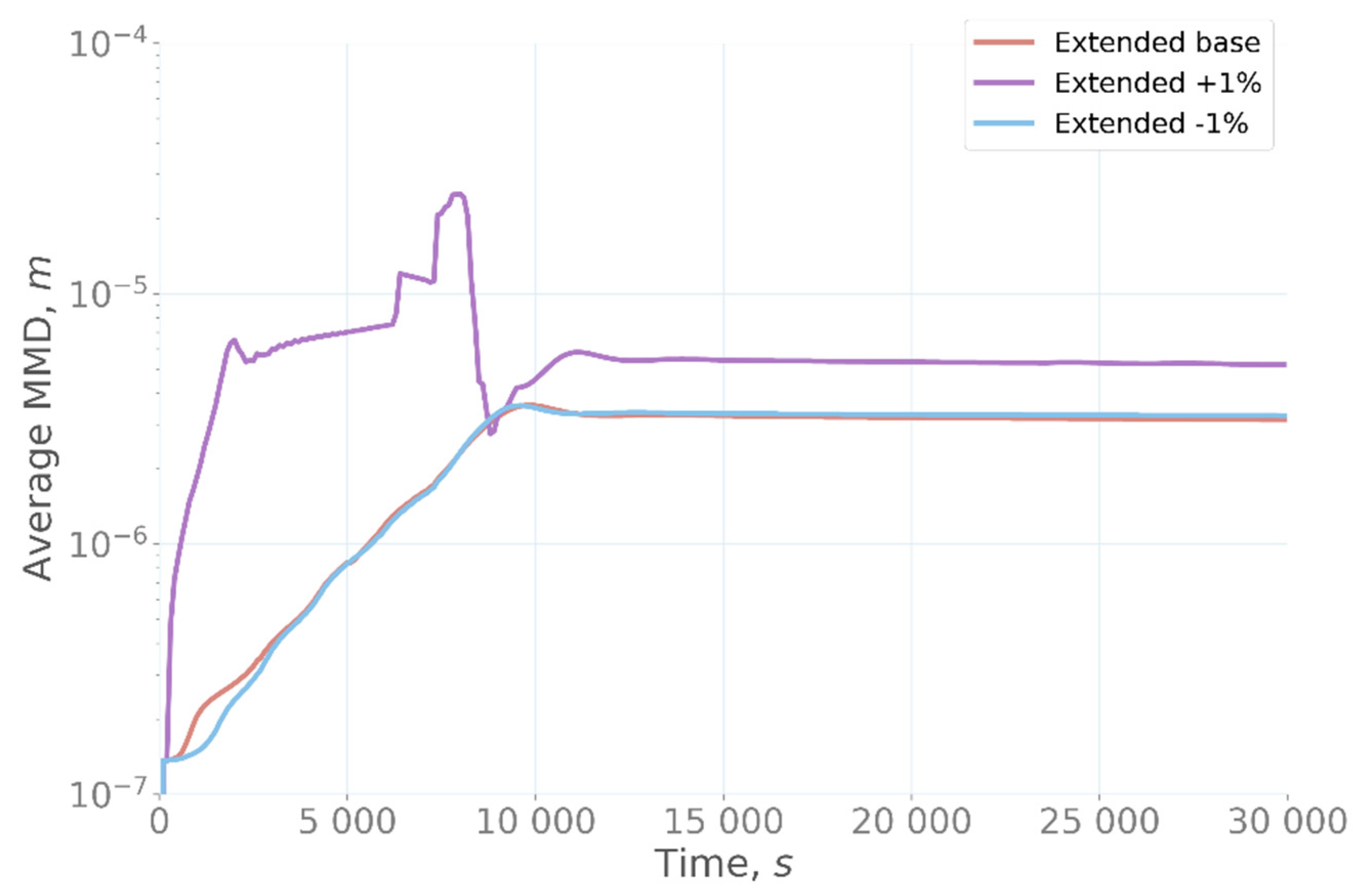
In both the base-case simulation and in the under-fluorinated simulation, the average mass median diameter (MMD) of the aerosol in the confinement increased until approximately 9500 s, as calculated by MELCOR. After that, the particle size reached a steady value of approximately MMD = 3.3 µm (
Figure 9) [
22]. In the over-fluorinated case, the particle size increased rapidly due to the very large release of UF
5 from the salt at the beginning of the simulation. After the particles reached their maximum size of MMD = 25 µm at approximately 7500 s, the UF
5 concentration in the particles started to decrease and the particle size rapidly decreased as a result of evaporation of UF
5 from the particles, as described above. After approximately 13,000 s, the particle size remained almost constant at 5.4 µm. This value is still larger than the one observed in the base case and under-fluorinated simulations, mostly due to the significant release of PuF
4, which condensed on the aerosol particles (in total more than 10 kg) after 10,000 s, causing the particle growth.
4. Discussion
The evaporation of fission products and salt compounds from MSR fuel under accident conditions was examined in this work. Simulations demonstrated that, when the salt was heated, considerable amounts of salt materials and actinide species were released and formed, partially, aerosol particles, due to the temperature drop from the salt bulk temperature to the surrounding confinement atmosphere gas temperature. Among the investigated species, the most volatile ones were LiF, UF4, ThF4, NpF4, ZrF4, UF5, and PuF4. Moreover, the volatility and the released amount of the species significantly depended on the fluorination of the salt. In particular, increasing the amount of fluorine in the salt by only 1 mol% significantly increased the volatility of UF5, NpF4, and PuF4. When the fluorine concentration was decreased by 1 mol%, the ThF3 became the most volatile species in the system. It is, however, worth noting that, independent of the fluorine amount in the system, at least within the calculated range, ZrF4 was shown to be the most volatile fission product species, with the behavior of other fission products showing little sensitivity to the amounts of fluorine present in the system.
The aerosol formation followed the trends shown by the evaporation of the fission products and salt compounds. In the base-case simulation, the formed aerosol mostly comprised ZrF
4, reaching a total of 79 kg in the confinement. A similar behavior was observed in the under-fluorinated case, in which the fluorine concentration was decreased by 1 mol% from the stoichiometric value. When fluorine concentration in the salt was increased by 1 mol%, evaporation of UF
5 was significantly increased, followed by rapid aerosol formation when the evaporated species cooled to the confinement gas temperature. This temperature decrease caused a high super-saturation of UF
5 in the gas phase, leading to aerosol formation by nucleation. It is important to highlight that salt fluorination plays also an important role in the average mass median diameter of the aerosol particles in the confinement. As can be seen from the
Figure 9 [
22], MMD reaches a steady value of approximately MMD = 3.3 µm after around 9500 s in both the base and under-fluorinated cases. In the over-fluorinated case, the aerosol formation in the confinement was more dynamic, leading to rapid changes in the aerosol concentration. In the over-fluorinated case, a large amount of UF
5 was released to the confinement atmosphere in the beginning of the simulation, resulting in aerosol formation. Due to high UF
5 concentration, the aerosol particles grew to a very large size of MMD = 25 µm at around 7500 s simulation time. After that, the particle size gradually decreased due to settling and deposition on the surfaces, as well as evaporation. The final stable particle size of MMD = 5.4 µm was considerably larger than the particle size of MMD = 3.3 µm in the base case and under-fluorinated case simulations, emphasizing the effect of salt composition on the aerosol formation in the confinement. The larger particle size in the over-fluorinated simulation was mainly due to a larger amount of evaporated species, resulting in a higher concentration of gas-phase species in the confinement and, subsequently, larger aerosol particle size. It should be noted that a more detailed study of the fluorine-amount effects on the behavior of the salt components and fission products is a very complex task, which spans outside the scope of the current research and would be a subject of a separate study.
5. Conclusions
The results obtained in this study indicate that significant amounts of salt materials and fission products may be evaporated from the MSR salt in a hypothetical accident which postulates that the core is drained to the confinement bottom and heats up by decay heat. In the confinement, a fraction of the evaporated material forms aerosol particles, and a fraction stays in the confinement atmosphere in the gas phase. In the simulations of this work, the size of the aerosol particles was mainly in the range MMD = 3–5 µm, which is similar to the particle size expected in the containment of light-water reactors [
8]. Similar to light-water reactor containments, aerosol particles would be expected to deposit on different MSR confinement surfaces, but due to the lack of detailed geometry of the confinement, these processes were not included in the simulations. The absence of steam in the MSR confinement would be expected to result in distinctly different deposition rates as compared to LWRs in which the diffusiophoresis caused by steam condensation is one of the major aerosol deposition mechanisms.
The simulations indicated that zirconium, especially in the form of ZrF4, can be very volatile in MSR designs utilizing fluorine under the accident conditions simulated in this work. It can exist as aerosol and in the gas phase in the confinement, and due to the active Zr isotopes, especially Zr-95, it should potentially be taken into account in the source term analysis of MSR accident conditions. The results show also high volatility and release of UF5 from the salt with only 1% excess fluorine, indicating the need for further investigation of this issue. Possible new information on the behavior of these and other fission products and salt materials are foreseen to be acquired in the SAMOSAFER project, which will include experimental investigation of the volatility of an irradiated fuel salt.
In general, the simulations showed that the release of salt material was very sensitive to even small changes in the fluorine content, as only 1% deviation from the stoichiometric fluorine concentration resulted in orders-of-magnitude differences in the release of certain compounds.
Author Contributions
S.N., conceptualization, methodology, software, investigation, formal analysis, writing—review and editing, and visualization; J.K., conceptualization, methodology, validation, investigation, visualization, writing—review and editing; T.L., conceptualization, supervision, validation, and writing—original draft preparation. All authors have read and agreed to the published version of the manuscript.
Funding
This work has received funding from the Euratom research and training program 2019–2023, under grant agreement No 847527.
Data Availability Statement
Not Applicable.
Acknowledgments
This work received funding from the Euratom research and training program 2014–2018, under grant agreement No. 847527. We would like to thank the SAMOSAFER project partners for fruitful collaboration.
Conflicts of Interest
The authors declare no conflict of interest.
References
- OECD/NEA. State-of-the-Art Report on Nuclear Aerosols; OECD/NEA: Paris, France, 2009. [Google Scholar]
- OECD/NEA. State of the Art Report on Iodine Chemistry; OECD/NEA: Paris, France, 2007. [Google Scholar]
- Compere, E.L.; Bohlmann, E.G.; Kirslis, S.S.; Blankenship, F.F.; Grimes, W.R. Fission Product Behavior in the Molten Salt Reactor Experiment; ORNL: Oak Ridge, TN, USA, 1975. [Google Scholar]
- SAMOSAFER Project. Available online: https://samosafer.eu/ (accessed on 31 January 2022).
- EVOL Project. Available online: https://cordis.europa.eu/project/id/249696/reporting (accessed on 31 January 2022).
- SAMOFAR Project. Available online: http://samofar.eu/ (accessed on 26 January 2022).
- Humphries, L.L.; Beeny, B.A.; Gelbard, F.; Louie, D.L.; Phillips, J. MELCOR Computer Code Manuals Vol. 2: Reference Manual; Sandia National Laboratories: Albuquerque, NM, USA, 2017. [Google Scholar]
- Kulik, D.A.; Wagner, T.; Dmytrieva, S.V.; Kosakowski, G.; Hingerl, F.F.; Chudnenko, K.V.; Berner, U.R. GEM-Selektor Geochemical Modeling Package: Revised Algorithm and GEMS3K Numerical Kernel for Coupled Simulation Codes. Comput. Geosci. 2012, 17, 1–24. [Google Scholar] [CrossRef] [Green Version]
- Shcherbina, N.; Kivel, N.; Günther-Leopold, I.; Kulik, D.A.; Bertsch, J. HERACLES Project and Thermodynamic Database. Available online: https://www.psi.ch/en/heracles/gems-specific-heracles-database (accessed on 15 December 2021).
- Nichenko, S. CGEMS Package: Coupling between GEMS and MELCOR. Available online: https://github.com/sergiinichenko/cgems (accessed on 15 December 2021).
- Nichenko, S.; Kalilainen, J.; Moguel, L.F.; Lind, T. Modelling of Fission Products Release in VERDON-1 Experiment with CGEMS: Coupling of Severe Accident Code MELCOR with GEMS Thermodynamic Modelling Package. Ann. Nucl. Energy 2021, 152, 107972. [Google Scholar] [CrossRef]
- Kalilainen, J.; Nichenko, S.; Krepel, J. Evaporation of Materials from the Molten Salt Reactor Fuel under Elevated Temperatures. J. Nucl. Mater. 2020, 533, 152134. [Google Scholar] [CrossRef]
- Capelli, E.; Beneš, O.; Colle, J.Y.; Konings, R.J.M. Determination of the Thermodynamic Activities of LiF and ThF4 in the LixTh1−xF4−3x Liquid Solution by Knudsen Effusion Mass Spectrometry. Phys. Chem. Chem. Phys. 2015, 17, 30110–30118. [Google Scholar] [CrossRef] [Green Version]
- Capelli, E.; Beneš, O.; Konings, R.J.M. Thermodynamic Assessment of the LiF-ThF4-PuF3-UF4 System. J. Nucl. Mater. 2015, 462, 43–53. [Google Scholar] [CrossRef]
- Capelli, E.; Beneš, O.; Konings, R.J.M. Thermodynamics of Soluble Fission Products Cesium and Iodine in the Molten Salt Reactor. J. Nucl. Mater. 2018, 501, 238–252. [Google Scholar] [CrossRef]
- Beneš, O.; Beilmann, M.; Konings, R.J.M.J.M. Thermodynamic Assessment of the LiF–NaF–ThF4–UF4 System. J. Nucl. Mater. 2010, 405, 186–198. [Google Scholar] [CrossRef]
- Glynn, P. Solid Solution Solubilities and Thermodynamics: Sulfates, Carbonates and Halides. Rev. Miner. Geochem. 2000, 40, 481–511. [Google Scholar] [CrossRef]
- Vozarova, N. Behaviour of Fission Products in the Molten Salt Reactor Fuel. Master’s Thesis, Swiss Federal Institute of Technology, Lausanne, Switzerland, August 2016. [Google Scholar]
- Barton, C.J.; Strehlow, R.A. Phase Relations in the System LiF-PuF3. J. Inorg. Nucl. Chem. 1961, 18, 143–147. [Google Scholar] [CrossRef]
- Capelli, E.; Beneš, O.; Konings, R.J.M. Thermodynamic Assessment of the LiF–NaF–BeF2–ThF4–UF4 System. J. Nucl. Mater. 2014, 449, 111–121. [Google Scholar] [CrossRef]
- Hombourger, B.; Křepel, J.; Pautz, A. The EQL0D Fuel Cycle Procedure and Its Application to the Transition to Equilibrium of Selected Molten Salt Reactor Designs. Ann. Nucl. Energy 2020, 144, 107504. [Google Scholar] [CrossRef]
- Nichenko, S.; Kalilainen, J.; Lind, T. MSR Simulation with CGEMS: Fission Product Release and Aerosol Formation. Available online: 10.5281/zenodo.6074656 (accessed on 15 December 2021).
| Publisher’s Note: MDPI stays neutral with regard to jurisdictional claims in published maps and institutional affiliations. |
© 2022 by the authors. Licensee MDPI, Basel, Switzerland. This article is an open access article distributed under the terms and conditions of the Creative Commons Attribution (CC BY) license (https://creativecommons.org/licenses/by/4.0/).


