
Nuclide Inventory Benchmark for BWR Spent Nuclear Fuel: Challenges in Evaluation of Modeling Data Assumptions and Uncertainties †


Oak Ridge National Laboratory, Bldg. 5700, P.O. Box 2008, Oak Ridge, TN 37831-6170, USA
*
Author to whom correspondence should be addressed.
†
This manuscript has been authored by UT-Battelle, LLC, under contract DE-AC05-00OR22725 with the US Department of Energy (DOE). The US government retains and the publisher, by accepting the article for publication, acknowledges that the US government retains a nonexclusive, paid-up, irrevocable, worldwide license to publish or reproduce the published form of this manuscript, or allow others to do so, for US government purposes. DOE will provide public access to these results of federally sponsored research in accordance with the DOE Public Access Plan (https://energy.gov/downloads/doe-public-access-plan , accessed on 10 December 2021).
J. Nucl. Eng. 2022, 3(1), 18-36; https://doi.org/10.3390/jne3010003
Submission received: 10 December 2021
/
Revised: 21 January 2022
/
Accepted: 26 January 2022
/
Published: 31 January 2022
Abstract
:This work discusses challenges and approaches to uncertainty analyses associated with the development of a nuclide inventory benchmark for fuel irradiated in a boiling water reactor. The benchmark under consideration is being developed based on experimental data from the SFCOMPO international database. The focus herein is on how to address missing data in fuel design and operating conditions that are important for adequately simulating the time-dependent changes in fuel during irradiation in the reactor. The effects of modeling assumptions and uncertainties in modeling parameters on the calculated nuclide inventory were analyzed and quantified through computational models developed using capabilities in the SCALE code system. Particular attention was given to the impact of the power history and water coolant density on the calculated nuclide inventory, as well as to the effect of geometry modeling considerations not usually addressed in a nuclide inventory benchmark. These considerations include gap closure, channel bow, and channel corner radius, which do not usually apply to regular reactor operation but are relevant for assessing impacts of potential anomalous operating scenarios.
1. Introduction
To validate the computational tools and associated nuclear data used for design and safety analyses of spent nuclear fuel transportation, storage, and repository systems, benchmarks must be developed that are based on experimental data for nuclide inventories. The world’s largest resource of publicly available experimental data of nuclide inventories in spent nuclear fuel is the SFCOMPO database [1], which is maintained by the Organisation for Economic Co-operation and Development (OECD)/Nuclear Energy Agency (NEA). Preservation and further expansion of this database are being coordinated by the SFCOMPO Technical Review Group (TRG), recently formed under the direction of the OECD/NEA Nuclear Science Committee/Working Party on Nuclear Criticality Safety. The current focus of the SFCOMPO TRG is the critical evaluation of the existing experimental assay data [2] to develop benchmarks and benchmark models for use by the international community. Such an effort includes unique challenges [2,3] that are different from those associated with benchmarks developed and published by the NEA’s International Reactor Physics Experiment Evaluation Project (IRPhEP) [4] and International Criticality Safety Benchmark Experiment Project (ICSBEP) [5]. These distinctive challenges include the treatment of time-dependent operating data for accurately simulating the nuclear transmutation and decay processes in fuel during irradiation, as well as the assessment of associated uncertainties in modeling assumptions and in radiochemistry experiments. Currently, there are no SFCOMPO evaluated benchmark reports that have been publicly distributed by OECD/NEA [3].
This paper discusses some of the challenges encountered and the approaches devised for addressing uncertainties in an SFCOMPO evaluated benchmark that is being developed based on radiochemistry experimental data for fuel irradiated in the Fukushima-Daini-1 boiling water reactor (BWR). Radiochemistry experiments are performed on fuel samples of fuel pellet size that are extracted from spent fuel rods. Details of fuel design and reactor operating conditions are needed to develop a well-founded benchmark for accurately simulating the physics at the measured sample and fuel rod location within the fuel assembly; however, such detailed data are often missing or incomplete. Fuel design data have inherent uncertainties due to manufacturing tolerances, and they are not generally provided by the fuel designer. Moreover, the operating condition data are generally provided for the average assembly or an axial level of the assembly and thus are not directly applicable to the samples being measured. Assumptions are necessary to substitute the missing data. The focus herein is how to address missing data that are important for adequately simulating time-dependent changes in the fuel during irradiation in the reactor. The effects of modeling assumptions and uncertainties in modeling parameters on the calculated nuclide inventory are analyzed and quantified through computational models developed using capabilities in the SCALE nuclear analysis code system [6].
2. Overview of Experimental Data
The experimental data that serve as the basis of the SFCOMPO benchmark under development include measured nuclide inventories for fuel samples selected from fuel rods irradiated in the Fukushima-Daini-1 BWR operated in Japan. Experiments on this fuel were performed by the Japan Atomic Energy Agency (JAEA) in two measurement campaigns. The measurement data, for which calculation–experiment comparisons are discussed herein, were obtained in the second measurement campaign and included isotopes of the major actinides U and Pu and of fission products Cs, Eu, Gd, Mo, Nd, Rh, Ru, Sm, and Tc [7,8]. The first campaign included only measurements for U, Pu, and Nd. The main applied measurement techniques consisted of (1) thermal ionization mass spectrometry (TIMS) for U, Pu, and Nd isotopes and (2) high-resolution inductively coupled plasma mass spectrometry (HR-ICP-MS) for isotopes of Cs, Eu, Gd, Mo, Nd, Rh, Ru, Sm, and Tc.
The five samples analyzed here were selected from five fuel rods irradiated within two fuel assemblies, identified as 2F1ZN2 and 2F1ZN3, and include both regular (UO2) fuel and gadolinia (UO2-Gd2O3) fuel. Fuel assemblies 2F1ZN2 and 2F1ZN3 both had a 9 × 9 – 9 lattice design and were irradiated for four and five consecutive reactor cycles, respectively. The characteristics of the measured fuel samples—fuel type, enrichment, Gd loading for the gadolinia rods, average void fraction at sample axial location, and reported sample burnup—are summarized in Table 1. The sample identifier (ID) in Table 1 includes the assembly identifier, rod identifier (i.e., C2), and the specific sample in the fuel rod (i.e., GdT) to indicate the type of fuel (Gd for gadolinia fuel and U for UO2) and the axial location in the fuel rod (T for top of the rod and M for middle of the rod). The cooling time for these five samples, from fuel discharge from the reactor to the time of measurement, varies in the range of 7–12 years, depending on the sample and nuclide measured. Three of these five samples are high burnup samples (>50 GWd/MTU), and the highest burnup is ~68 GWd/MTU. To date, the sample with 54 GWd/MTU burnup is the highest burnup gadolinia fuel sample for which measurements of 155Gd have been reported in the literature. The 155Gd nuclide is a very strong neutron absorber with a significant impact on burnup credit applications and peak reactivity effects in BWRs during reactor operation. Note that from the over 750 samples with measurement data provided in the SFCOMPO database for different reactor types and fuel designs, there are only five gadolinia fuel samples with 155Gd measurements. Two of these samples are shown in Table 1.
3. Computational Models
Benchmark specifications for the samples listed in Table 1 were developed based on data available in the primary references included in the SFCOMPO database [1]; additional resources and assumptions were used to complement the primary references for missing or incomplete data. These benchmark specifications include sample burnup; fuel assembly design data (assembly lattice layout, assembly pitch, number of regular fuel rods and gadolinia rods, intrachannel width, channel thickness, bypass gap thickness, and channel corner radius); fuel rod design data (fuel rod pitch, fuel pellet radius and material, and clad radii and material); material composition and temperature data for fuel, clad, and water coolant and moderator; and time-dependent operating history data (power, water coolant density, and fuel temperature), as applicable. Uncertainties are inherent in all of these data. It is not the purpose of this paper to list all of these specifications in detail; these will be presented in detail in an upcoming SFCOMPO evaluation. Instead, this work emphasizes the challenges associated with incomplete or missing data assumptions and quantifies the impact of these assumptions and the impact of uncertainty in modeling data on the predicted nuclide inventory. The accuracy of the prediction is usually quantified via the calculated-to-experimental (C/E) nuclide concentration ratio.
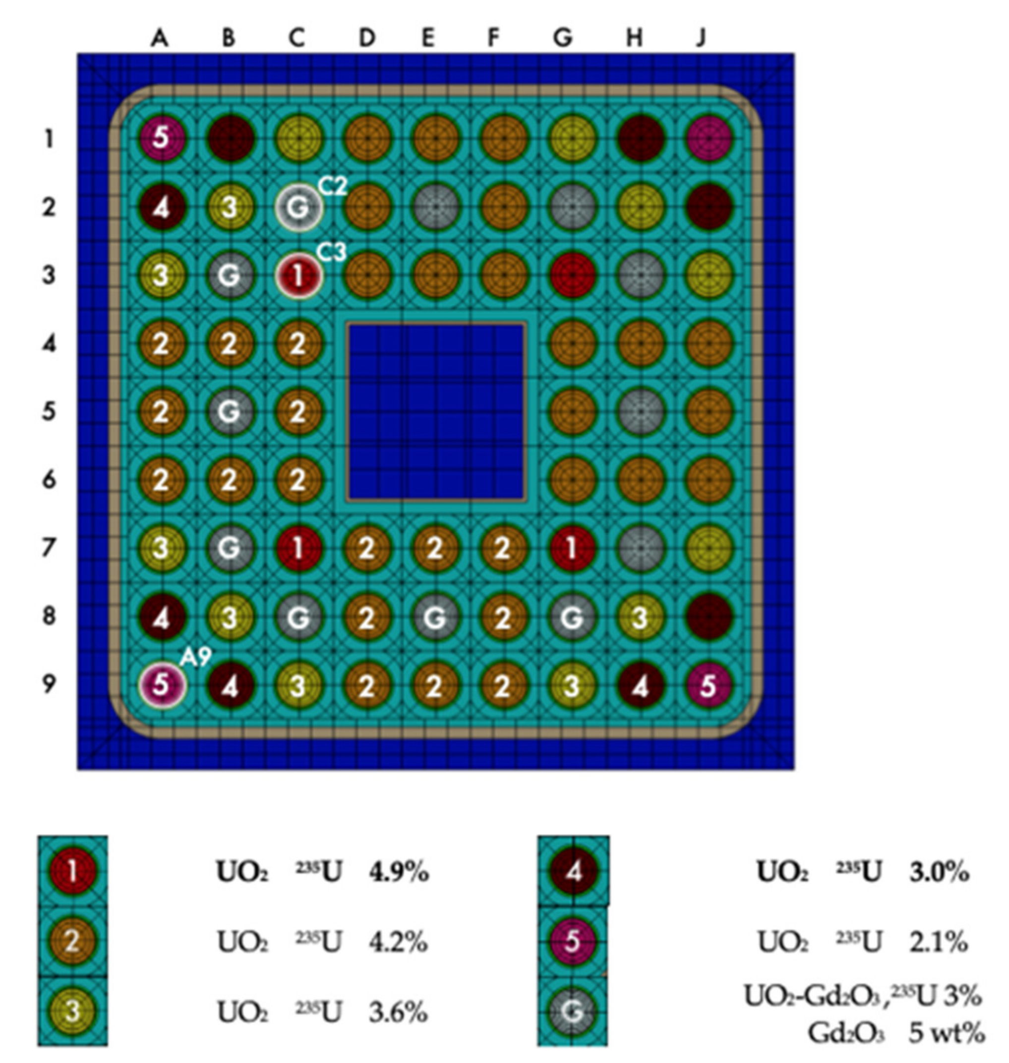
Computational models for this benchmark were developed with SCALE’s Polaris lattice physics code [10,11] to determine the C/E values for the measured nuclide inventories in the samples and to assess the uncertainties in C/E caused by modeling assumptions and modeling parameter uncertainties. Polaris, which showcases an input format that allows users an easy setup of light-water reactor lattice models, couples a method of characteristics (MOC) neutron transport solver and the ORIGEN depletion and decay code [12] in SCALE to simulate the time-dependent fuel depletion history. The geometry of these computational models is illustrated in Figure 1, which shows a 2D representation of the fuel assembly, indicating the fuel rod location and enrichment profile and the location of the rods from which the measured samples listed in Table 1 were selected. Gadolinia rods in the Polaris computational model were represented using a radial mesh with five equal-area regions to adequately model the strong self-shielding in these rods. All depletion simulations were performed with Polaris in SCALE version 6.2.3 and with the 56-group cross-section library based on ENDF/B-VII.1 evaluated data.
Burnup is the major driver of the nuclide inventory in spent nuclear fuel discharged from the reactor and is therefore a very important modeling parameter. The sample burnups listed in Table 1 were derived in [7,9] based on the measured concentration of the 148Nd burnup indicator fission product and are generally referred to as measured burnups. The sample burnups that correspond to the C/E results obtained with SCALE and presented herein were estimated based on code calculations with Polaris. The Polaris-calculated burnup was determined by (1) performing a depletion simulation of the fuel assembly using the measured sample burnups listed in Table 1 as a basis, followed by (2) a second depletion simulation in which the sample burnup was normalized to the measured 148Nd burnup indicator (i.e., the calculated concentration of this nuclide matched its reported measured concentration). Table 2 presents the Polaris-estimated sample burnups, along with other calculated values previously reported in the literature for these samples—which were estimated using core follow calculations with the SRAC and MVP-BURN codes [9]—to illustrate the level of the expected differences between code-calculated burnups and measured burnups. The Polaris-calculated burnups are within 1% of the measured burnups for all five samples. Differences in burnups calculated with different codes are primarily due to differences in the nuclear data used in simulations. Moreover, for gadolinia rods, accounting for the contribution to the calculated burnup of the energy released in 157Gd and 155Gd (n,γ) reactions, which can be handled differently by different codes, plays an especially important role at lower burnups. The energy release per neutron capture for these (n,γ) reactions can vary based on the nuclear data set used in calculations.
4. Impact of Modeling Assumptions and Modeling Data Uncertainties
The development of nuclide inventory benchmarks for BWR spent fuel presents different challenges from those of similar efforts for pressurized water reactor (PWR) spent fuel, given the increased radial and axial heterogeneity of the fuel configuration and complexity of the operating history for BWRs compared to PWRs. Axial information (e.g., water coolant density, presence of full- or part-length rods, rod power, and assembly power) for BWRs is essential for adequately capturing the underlying physics. Often, this type of axial information is not available, and well-founded assumptions are necessary. The most significant challenge is how to treat the uncertainty for time-dependent operating parameters such as the operating power history, which is not commonly reported. Although most nuclides present in spent fuel generally have low sensitivity to power history for a given burnup, there are several short-lived fission products with high sensitivity, especially to power history near the end of irradiation [2].
Because of incomplete or missing data and the associated uncertainty for assembly design, fuel characteristics, and operating history parameters, the benchmark being developed for the Fukushima-Daini-1 spent fuel samples included several assumptions. The basis of these assumptions and their impact on the C/E nuclide concentration ratio are presented here. The impacts of these assumptions are assessed based on the direct perturbation of specific modeling parameters. The type of uncertainties and assumptions include the following:
- Assembly and fuel rod geometry: manufacturing tolerances in assembly pitch, fuel rod pitch, fuel rod dimensions, clad thickness, and channel wall and water box dimensions;
- Material composition: manufacturing tolerances in fuel enrichment or lack of detailed initial uranium isotopic composition;
- Operating history: axial and radial intranodal void fraction distribution, temperature of fuel and coolant, density of fuel, measured sample power history and burnup, and geometry changes due to operating history (i.e., gap closure, channel/rod bow).
4.1. Power History
Ideally, the time-dependent variation of power or equivalently burnup at the radial and axial locations within the fuel assembly that corresponds to the measured fuel sample is needed to accurately simulate the nuclear transmutation and decay processes in the sample during irradiation. This type of data is not generally available. What is usually available from the reactor core simulator used to manage the reactor operation is the so-called nodal power, which is the radially averaged power across the assembly within an axial layer or node (node height ~10 cm) of the assembly. The power within the measured sample (sample height ~1 cm) can significantly differ from the nodal power because of heterogeneities within the assembly and the intranodal variation of the neutron flux. Additionally, there are uncertainties in the reported nodal power due to inherent uncertainties associated with the reactor core simulation method.
The benchmark specifications assumed that the time-dependent power at the sample axial location is proportional to the time-dependent nodal power available from the core simulator. The sample-specific power for the benchmark was calculated by scaling the nodal power history to the reported sample burnup. Because it is easy to implement, this type of approach is generally used by analysts. The effect of this assumption is evaluated herein using an alternate approach for deriving the sample power.
This second approach includes two steps. In the first step, a depletion simulation for the fuel assembly is performed with Polaris using the provided nodal average power as input assembly power, which is consistent with the available input data for that node; in this case, the neutron flux solution within the assembly is normalized by Polaris to this input assembly power. Note that the neutron flux solution in Polaris for an assembly depletion simulation can be normalized, based on the user’s selection, to the assembly power, power of a specific rod, or power of a set of specific rods.
The resulting output of the Polaris simulation in the first step includes the time-dependent power distribution within the assembly for each of the fuel rods, including the rod from which the measured fuel sample was selected. This time-dependent variation of the power in the fuel rod of interest serves as input for the second step. In the second step, the time-dependent variation of the power within the fuel rod is scaled to the reported sample burnup and then used as input for a second Polaris depletion simulation of the assembly. In this second depletion simulation, the flux solution is normalized to the power for the fuel rod of interest.
The two approaches presented above for power history modeling can be summarized as follows: (1) time-dependent sample power is obtained by scaling the available nodal average power history with the provided sample burnup, and (2) time-dependent sample power is obtained by scaling the derived fuel rod power history with the reported sample burnup. Although the second approach is code-dependent, it provides an estimate of the uncertainty in predicted nuclide concentration due to the modeling assumption (1) used for the benchmark. Both approaches have consistent sample burnups, but the trajectories of the power to reach that burnup may differ.
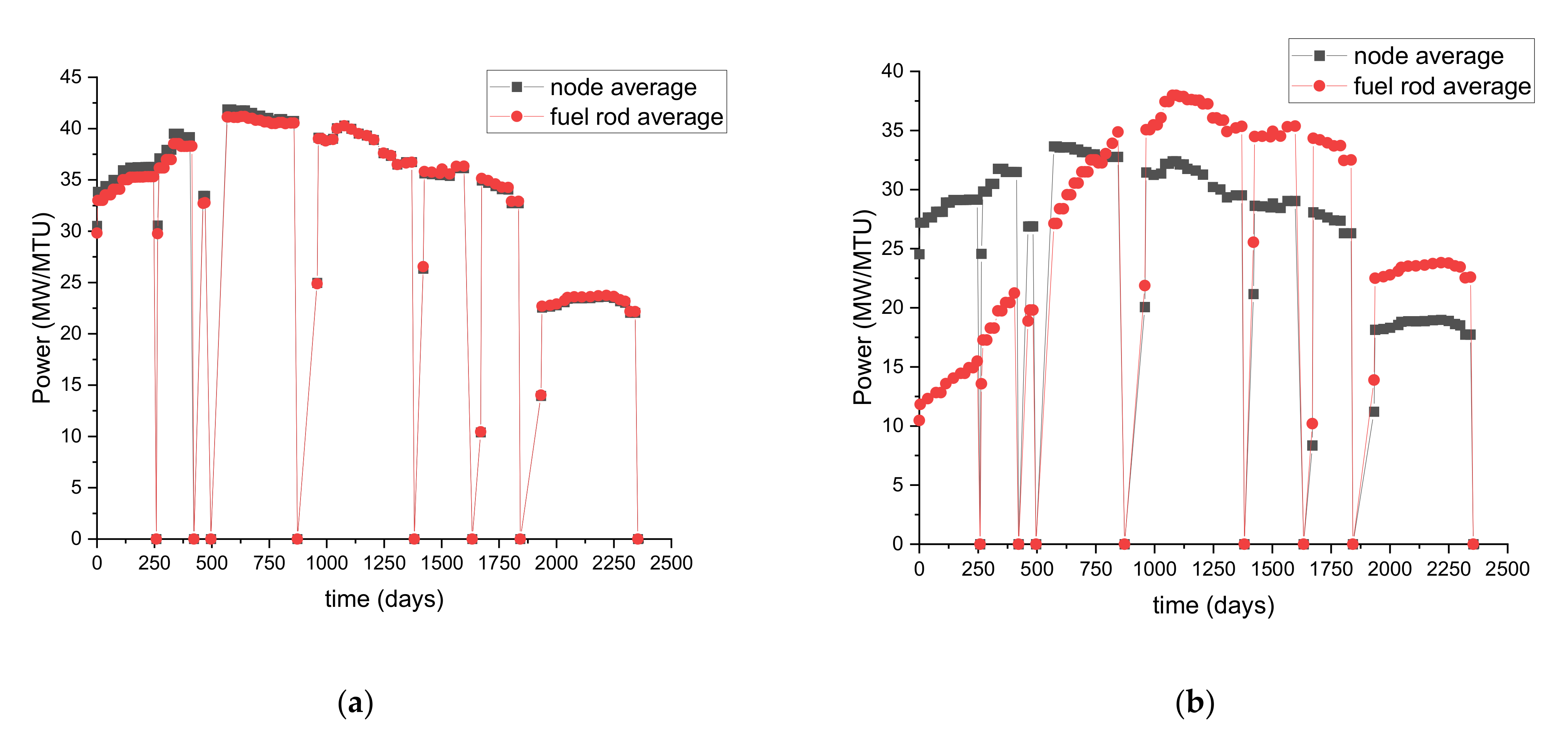
A comparison of the sample power history determined via the two approaches is illustrated in Figure 2 for a regular fuel rod (sample 2F1ZN3-C3-UM) and for a gadolinia rod (sample 2F1ZN3-C2-GdM) in assembly 2F1ZN3. Whereas the two approaches mentioned above lead to similar power trajectories for the regular fuel rod, the power trajectories for the gadolinia fuel rod show significant differences, which is expected because gadolinia rods have different neutronic characteristics from the average assembly behavior that is dominated by the regular fuel rods. This indicates that for regular fuel rods, the use of a sample power history based on node power history is adequate, whereas for the gadolinia fuel rods, it is not warranted.
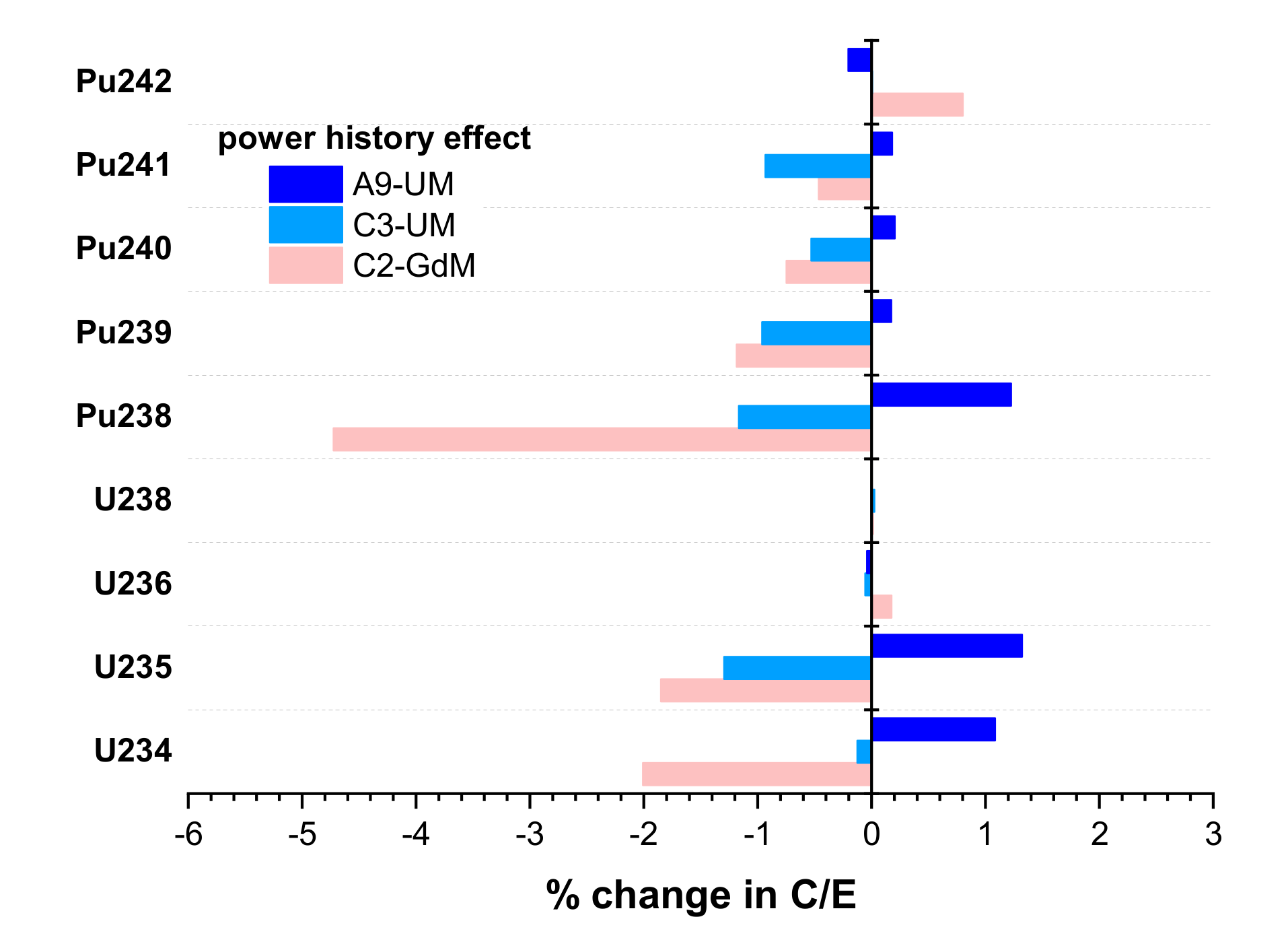
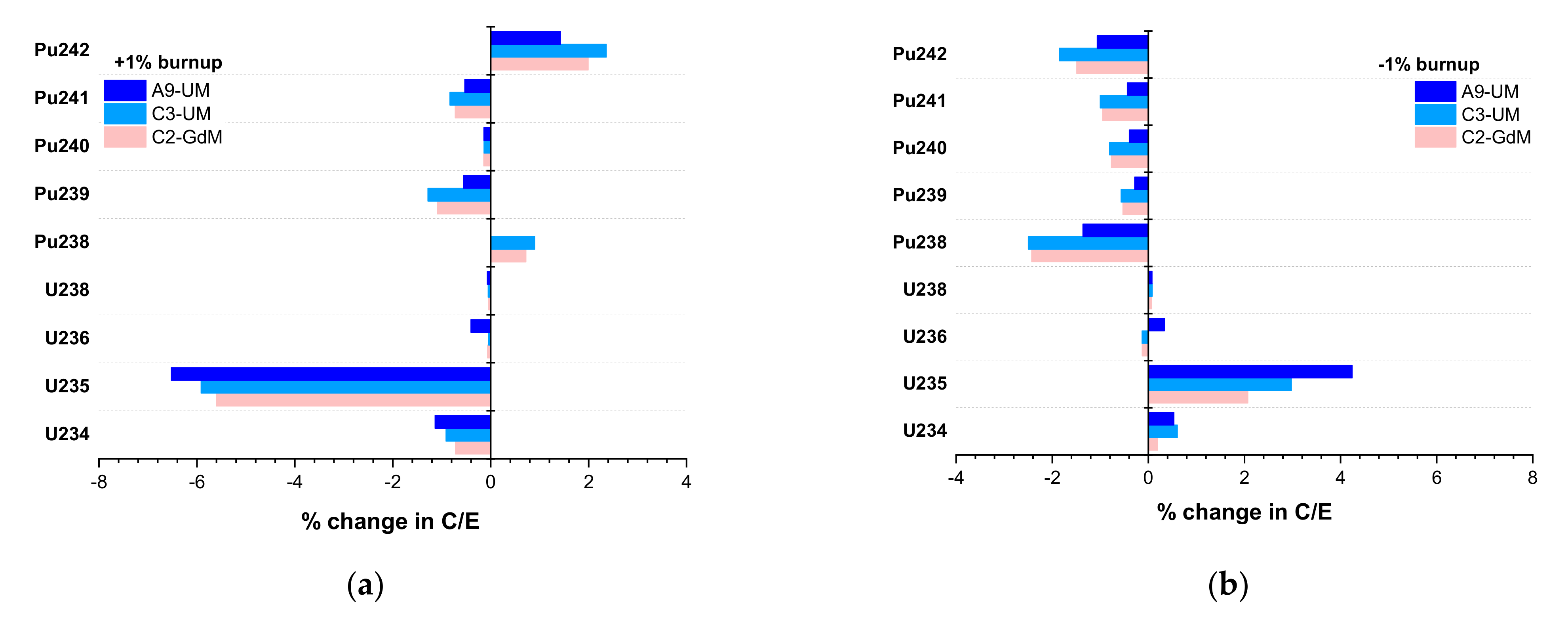
The effect of the assumption for sample power history on the C/E nuclide concentration ratios for U and Pu isotopes is illustrated in Figure 3 for three samples from assembly 2F1ZN3. These samples were selected to cover different types of fuel rods: corner rod, regular fuel rod, and gadolinia rod. Detailed C/E values are provided in Section 4, along with all other estimated uncertainties for these samples. The change in C/E is the primary focus here. For convenience, only the rod and the axial location of the sample ID are shown in the legend of Figure 3. For the regular fuel samples C3-UM and A9-UM, the power history approach leads to changes in C/E for U and Pu isotopes of less than ~1.5%. Conversely, the magnitude of the effect is greater for the gadolinia fuel sample C2-GdM for 234U and 235U (~2%) and for 238Pu (~5%).
4.2. Coolant Density
The density of the water coolant at the sample axial location is not generally provided. Available data usually include coolant void fractions for each axial node in the assembly. The usual approach, which was also applied for the benchmark specifications, is to assume that the void fraction at the sample axial location is the same as the corresponding axial node void fraction. This assumes that the void fraction is radially uniform within the node. However, the intranodal void fraction distribution is not uniform and may vary with the fuel rod power and fuel radial location in the assembly, particularly for rods in proximity to the water box and the channel box, as previously noted in the literature [13]. The coolant density around the sample could therefore be significantly different from the node’s average coolant density. Previous studies indicated that nodal average void fractions can have relative uncertainties of ~5% and that the void fraction for fuel rods that are close to the assembly periphery or in proximity to water rods can be significantly smaller—by up to 25%—than the node’s average void fraction [13].
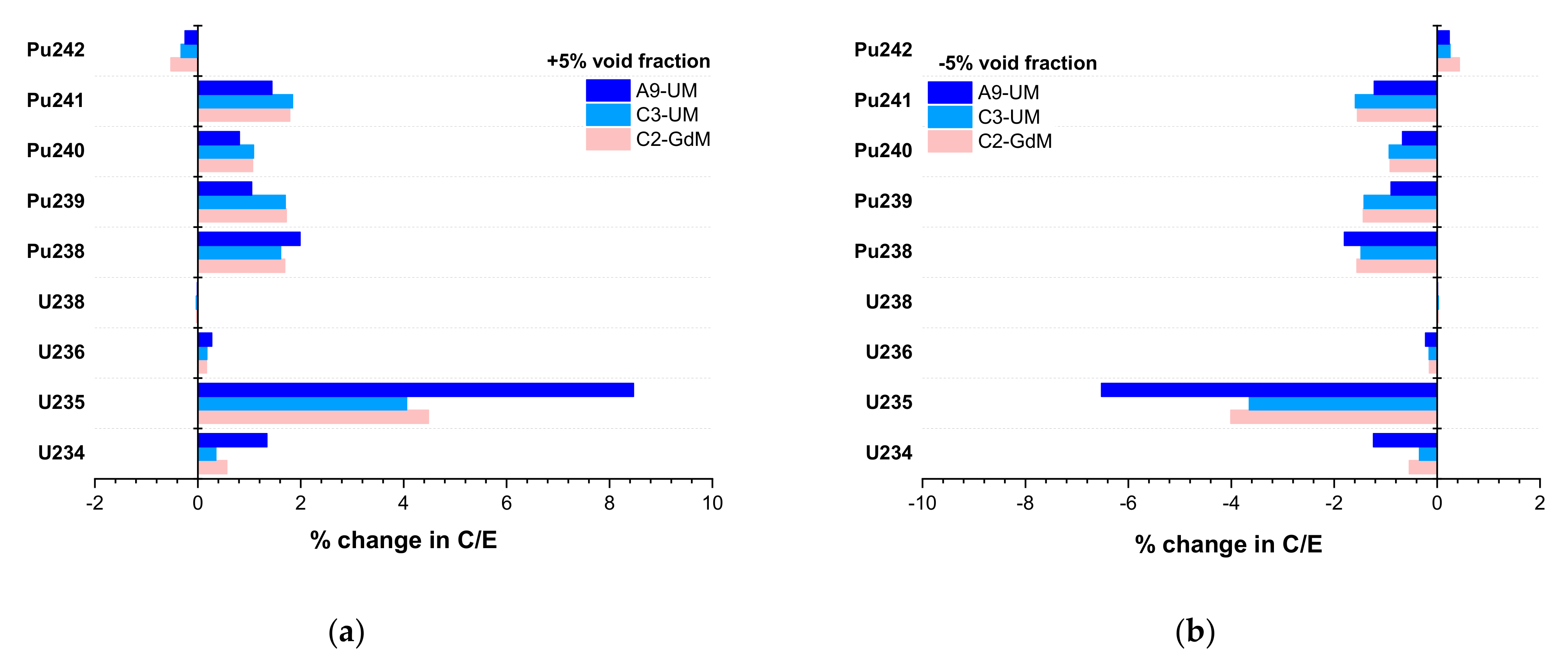
The effect of the void fraction assumption on the C/E nuclide ratios is estimated herein by assuming a 5% change in the void fraction. The results are illustrated in Figure 4 for U and Pu isotopes in samples from assembly 2F1ZN3. This figure shows the change in C/E due to a 5% relative increase (Figure 4a) and a 5% relative reduction (Figure 4b) in the sample void fraction. An increase in void fraction (decrease in coolant density) leads to the hardening of the neutron flux spectrum due to less moderation and consequently to an increase in predicted actinide concentrations, which are sensitive to the spectrum. Depending on the isotope, the C/E for Pu isotopes increases by up to 2%, and it increases by more than ~4% for 235U with increasing void fraction. The opposite behavior is observed if the void fraction is reduced. The largest change in C/E values is observed for sample 2F1ZN3-A9-UM from the corner rod A9. The large overprediction of 235U in this sample indicates that the actual void fraction history for this corner rod is likely lower than the node’s average void fraction.
It is important to note that the magnitude of the change in C/E with void fraction variation, for a constant variation of this fraction, is expected to increase with increasing axial elevation. This would result from a larger absolute value change in the void fraction (and therefore in the coolant density) with axial elevation, given that the void fraction increases with increasing elevation.
4.3. Fuel Data
4.3.1. Fuel Density
Fuel density is generally derived based on the available theoretical density (TD) of uranium oxide and the provided TD fraction for the considered fuel samples, as well as by accounting for the rod dishing data when available. The specifications for the benchmark considered herein assumed a 1% dishing [2], owing to a lack of specific information. Fuel density can be impacted by chamfering and dishing, the packing/compression ratio, or thermal expansion of the fuel rod caused by fuel burnup. Thermal expansion is addressed further in Section 4.4.2 alongside a discussion of the impact of geometry changes.
The effect of the 1% dishing assumption (i.e., 1% reduction in fuel volume) is quantified here by applying a 1% uncertainty (increase) in fuel density. This increase in fuel density and consequently in fuel mass would correspond to the fuel mass in the case in which dishing is neglected (0% dishing). The resulting change in the C/E ratios due to a 1% increase in fuel density is illustrated in Figure 5 for U and Pu isotopes in samples from assembly 2F1ZN3. The largest change (increase) of ~2% is observed for 235U, whereas the changes for the other nuclides are less than 1%.
4.3.2. Fuel Temperature
Fuel temperature is not available for the analyzed samples and is assumed to be constant throughout the fuel irradiation, as was also applied in previous similar analyses for BWR spent fuel [14]. For the benchmark specifications herein, the typical burnup-independent axial temperature profile provided by Radulescu [14] was used as a basis. However, as indicated by fuel performance studies, fuel temperature varies radially and axially with burnup and as a function of axial power shape and coolant temperature [14,15,16] and can vary by as much as 100 K with burnup for a BWR 9 × 9 fuel assembly [15].
The effect of fuel temperature uncertainty on the C/E ratios is estimated herein by perturbing the temperature value used in the benchmark specifications with 100 K. Figure 6 illustrates the effect of changing the fuel temperature (100 K increase and 100 K reduction) for samples from assembly 2F1ZN3. Increased fuel temperatures lead to increased actinide nuclide concentrations, except for 236U, which is practically unaffected, whereas reduction in fuel temperature has the opposite effect. The C/E variations for the samples from the corner rod (A9) and the gadolinia rod (C2) are more prominent than those for the regular fuel rod (C3). Although the effect of the fuel temperature change on the C/E is generally the result of the Doppler resonance broadening and the consequent change in the neutron flux spectrum, there are other effects to be considered when attempting to explain the different magnitudes of the C/E impact, depending on the sample. It should be noted that power, void fraction, and fuel temperatures are correlated so that low-power samples would have lower void fractions and lower fuel temperatures than the corresponding nodal average values.
4.4. Geometry
4.4.1. Gap Closure
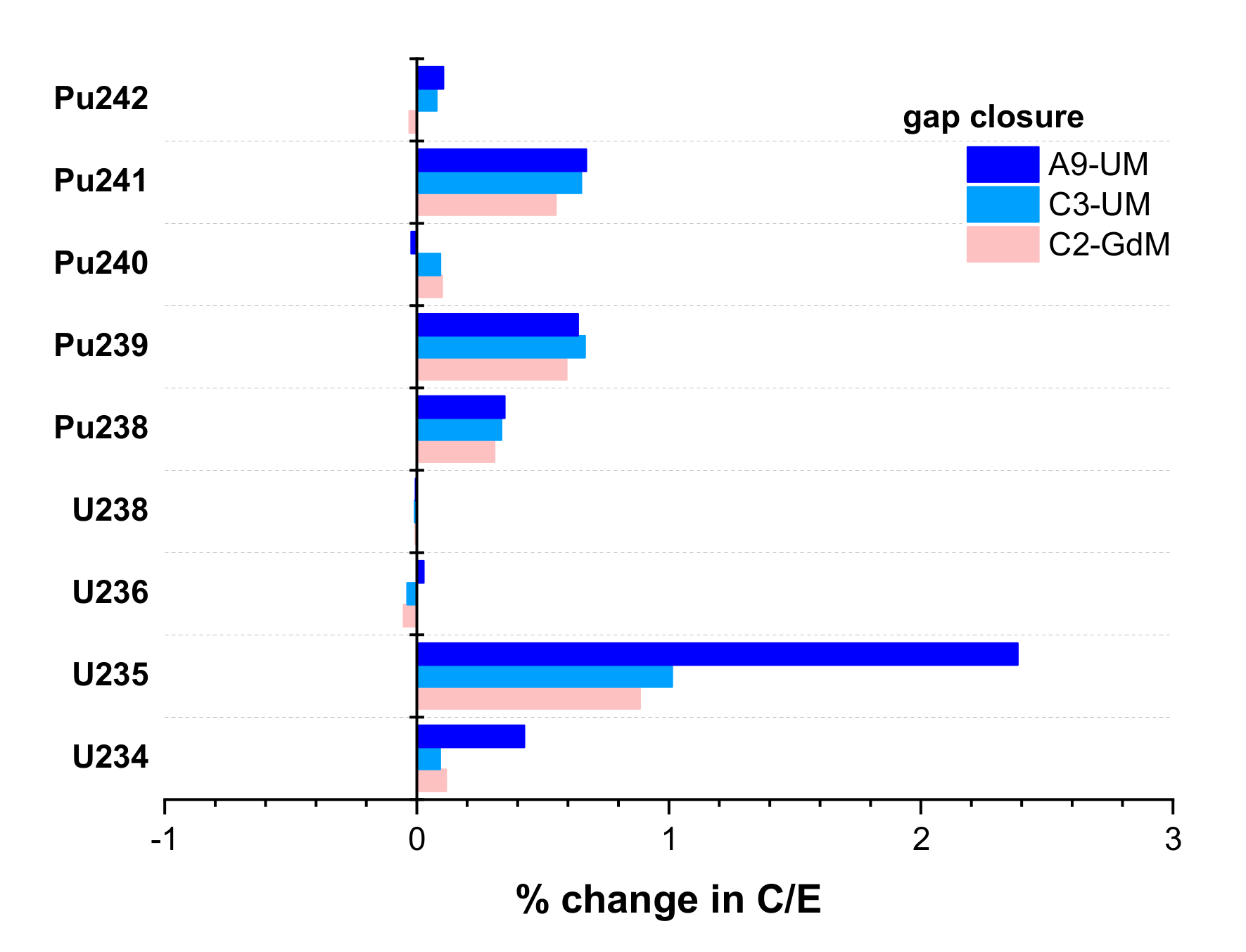
During irradiation, the fuel volume changes due to the fuel’s heating and swelling and fission gas buildup. Therefore, the gap between the fuel pellet and the clad changes. The effect of the gap closure is estimated here by assuming that the fuel pellet diameter is the same as the clad inner diameter, and therefore, no gap is present. At the same time, the fuel density is adjusted to conserve the total mass of initial fissile, as expressed in Equation (1), where r denotes the initial radius and ρ denotes fuel density.
This estimation of the gap closure effect ignores the changes in clad geometry caused by thermal expansion, which is separately discussed in Section 4.4.2. The effect of the gap closure on the C/E ratios for U and Pu isotopes is illustrated in Figure 7 for samples from assembly 2F1ZN3. The C/E values of U and Pu isotopes change by less than 1% with gap closure, except for 235U in the corner rod (A9) sample, which shows an increase of ~2.5%.
4.4.2. Thermal Expansion
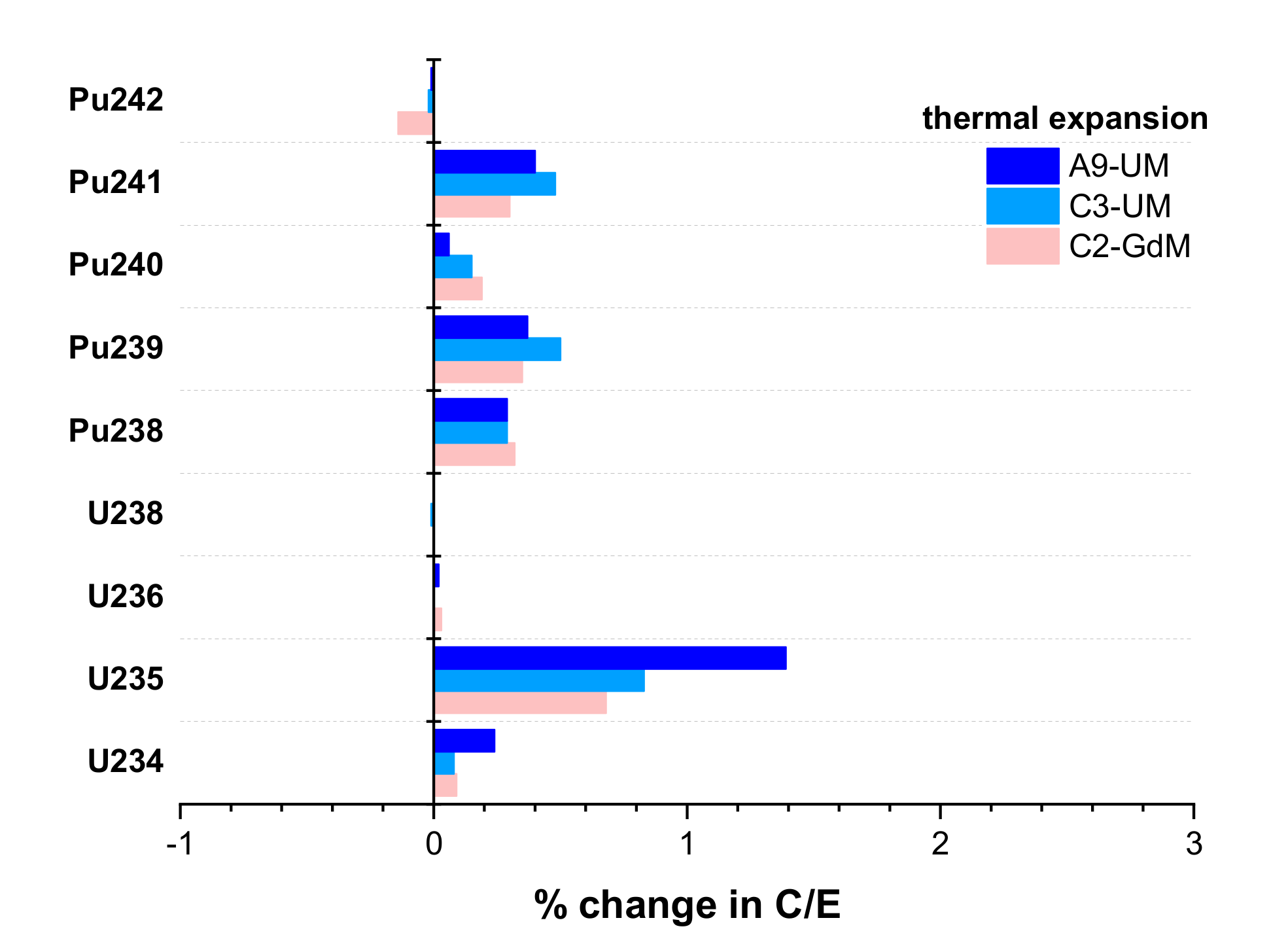
Geometry data for fuel rods and structural materials are generally provided at cold conditions (i.e., room temperature). However, reactors operate at high temperatures (i.e., hot conditions), and the geometry data provided at cold conditions do not account for changes in dimensions caused by thermal expansion during normal operation. To estimate the effect of thermal expansion on the C/E ratios, it was assumed that the relative change in four parameters—pellet radius, clad inner radius, clad outer radius, and fuel density—is the same as that applied in previous studies that investigated the effect of thermal expansion on criticality [17]. Fuel pellet radius was increased by 0.6%, and clad inner and outer radii were increased by 0.2%. Fuel density was changed to ensure fuel mass was conserved. The changes in C/E ratios caused by thermal expansion are illustrated in Figure 8 for U and Pu isotopes in samples from assembly 2F1ZN3. These changes are less than 1%, except for 235U in the corner rod (A9) sample, which is slightly greater.
4.4.3. Channel Bow/Bulge
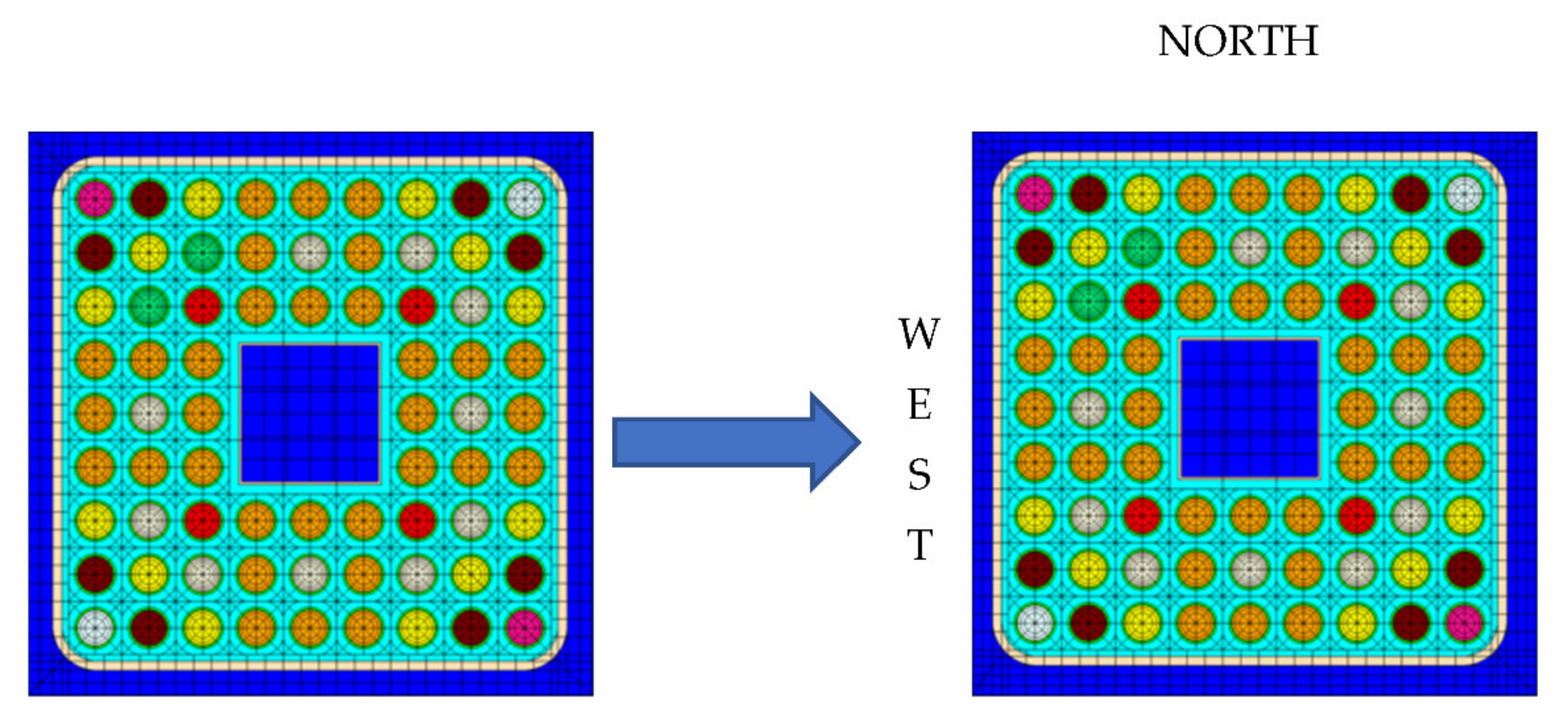
The fuel channel within the BWR fuel assembly can be subjected to dimensional changes during reactor operation, primarily driven by differential irradiation growth and/or differential hydrogen content across opposing faces of the channel, which would cause the channel to bow, bulge, or twist. Analysis with a lattice physics code of the different channel distortion types may be too complex a task. However, the channel bow can be easily modeled by modifying the width of the channel gap, as illustrated in Figure 9.
Previous studies indicated that the channel distortion rate is expected to increase after two irradiation cycles and that a 25% change in channel gap would cause the control blade to become stuck, which is the main concern with the channel bow [18]. For the estimation herein, a 20% shift is considered in the channel gap (see Figure 9) in the northeast direction (wide–wide corner), starting with the first irradiation cycle in the depletion simulation, for convenience.
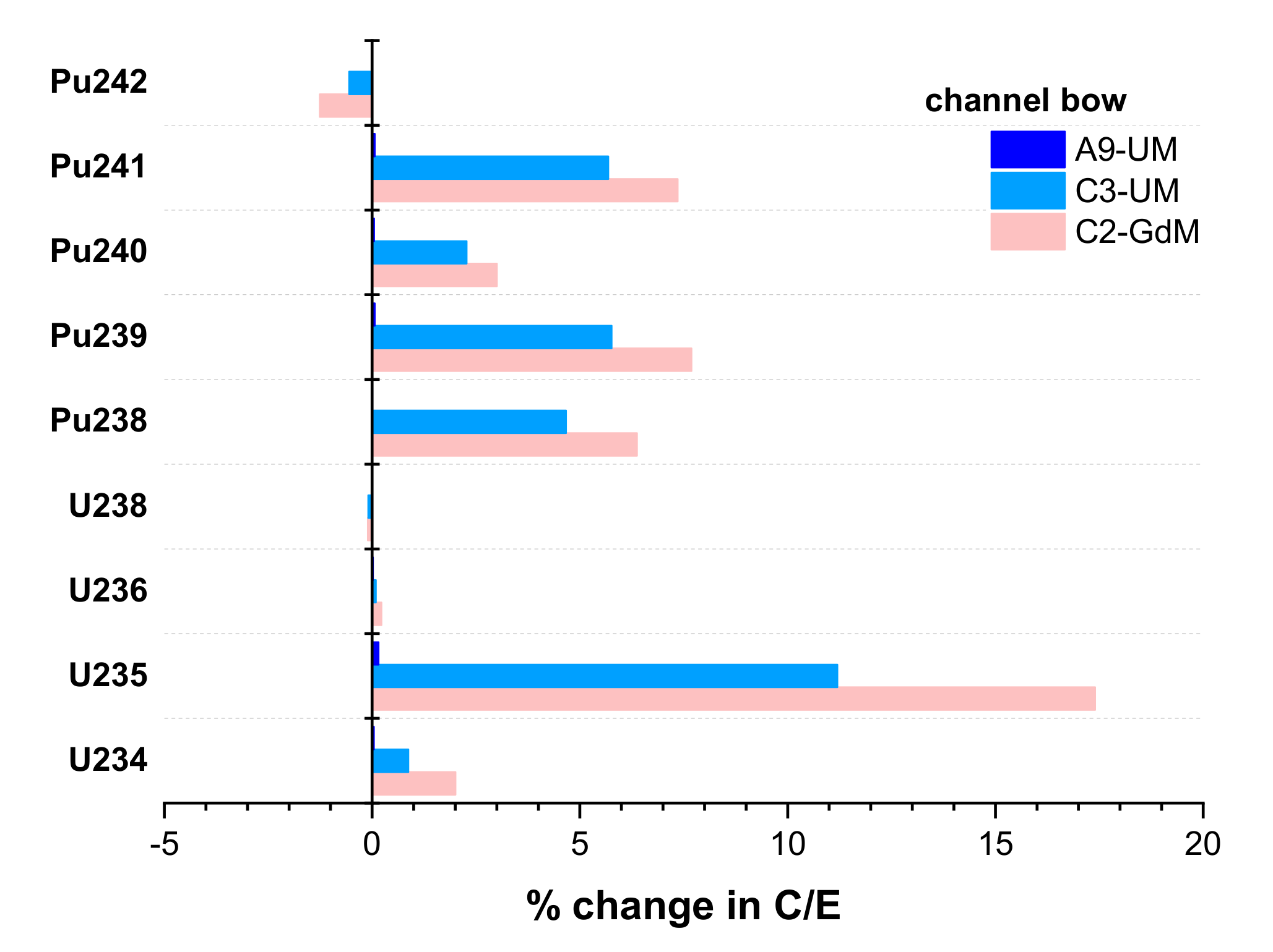
The resulting change in the C/E ratios due to the modeled channel bow is illustrated in Figure 10 for U and Pu isotopes in samples from assembly 2F1ZN3. No significant changes are observed for the sample from the corner rod (A9), as expected given that the average moderator thickness for this rod does not change. The samples from rods C2 and C3 show a large increase in 235U: 17% and 11%, respectively. The change in C/E for Pu isotopes, except for 242Pu, varies by 2–8% for the samples from rods C2 and C3. This impact is caused by rods C2 and C3 being subjected to reduced moderation from the west and north surfaces and the consequent hardening of the neutron flux spectrum.
4.4.4. Channel Corner Radius
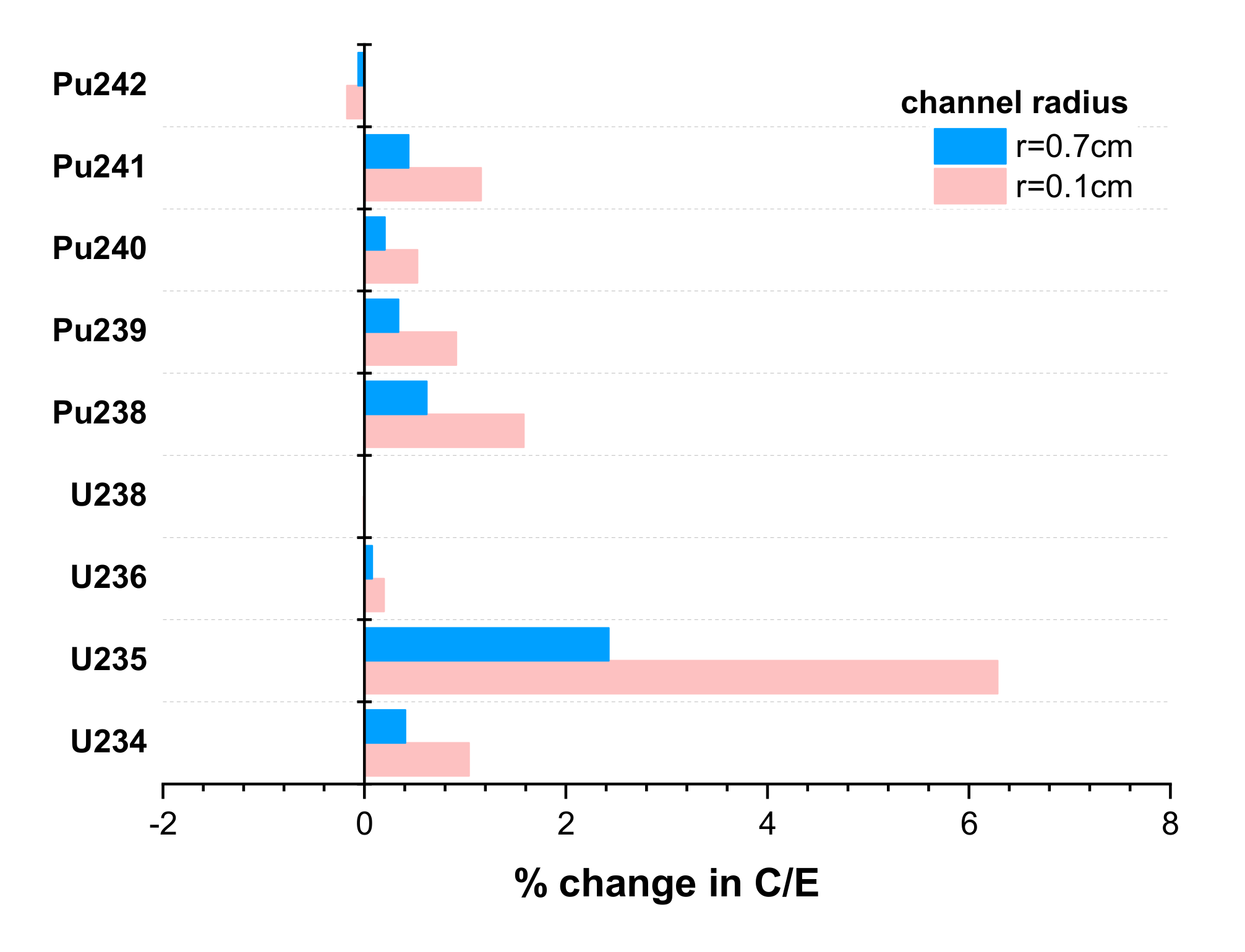
The channel corner radius was not available for the 9 × 9 – 9 assembly considered in the benchmark. It was assumed that this radius is the same (r = 0.9653 cm) as that available for an 8 × 8 BWR assembly [19]. Changes in this corner radius are not expected to lead to significant changes in predicted nuclide concentrations, except for fuel rods located at the corner of the assembly. For a corner rod, changes in the channel radius lead to changes in the coolant amount around this rod and, consequently, to changes in the neutron flux spectrum. The effect of the corner radius on nuclide concentration prediction in these rods is also expected to increase with increasing void fraction.
The effect of the corner radius is illustrated in Figure 11 for two values of the radius: (1) 0.1 cm, which is close to a square channel assumption (i.e., 0 cm radius), and (2) 0.7 cm. This figure shows the changes in the C/E for U and Pu isotopes in corner rod sample 2F1ZN3-A9-UM when changing the corner radius from its nominal benchmark value of 0.9653 cm to 0.1 cm or 0.7 cm. The C/E changes are less than 2%, except for 235U. For this isotope, the C/E effect increases to more than 6% if channels are modeled as a square. This indicates that the predicted 235U concentration in corner rods is largely underestimated if channels are modeled as a square.
4.4.5. Geometric Manufacturing Tolerances
Reported fuel geometry data have inherent manufacturing uncertainties. However, these uncertainties are generally proprietary and not publicly available. The SFCOMPO evaluation guide [2] recommends typical geometry uncertainties of ±10 μm for the fuel pellet radius and ±25 μm for the clad radius. However, considering that the change in fuel pellet radius due to thermal expansion (discussed in Section 4.4.2) is twice the recommended manufacturing tolerance, the relative effect on C/E ratios is expected to be less than 1%. The specific impact of this uncertainty is not addressed in the current study.
4.5. Burnup
The effect of burnup uncertainty on the C/E ratios is estimated herein for a 1% uncertainty, as illustrated in Figure 12 for samples from assembly 2F1ZN3. The largest change is observed for the C/E of 235U. Note that in the high-burnup range, as applicable to the considered samples, the concentration of this nuclide does not vary linearly with burnup and exhibits an exponential behavior. For the other considered nuclides, the C/E change is less than ~2%.
5. Results and Discussion
The C/E nuclide concentration ratios determined based on the nominal benchmark specifications for all five samples listed in Table 1 are presented to illustrate the level of agreement between calculation and experimental results and to provide a basis for assessing the relevance of the uncertainties discussed in Section 4. Total uncertainty values are presented for three samples from assembly 2F1ZN3, accounting for both computational and measurement uncertainties.
5.1. Comparison between Calculation and Experiment for Nuclide Inventories
Table 3 presents the (C/E-1) percentage values for the five considered samples, along with the mean and standard deviation of the five samples. The relative experimental uncertainty shown in the table corresponds to the maximum of the individual measurement uncertainty values reported for these samples. Note that no confidence levels are available for the reported measurement uncertainties, and it is not known whether they represent one or two standard deviations.
On average, the major actinides 235U and 239Pu are predicted within 3.7% (σ = 4.1%) and 1.5% (σ = 6.4%) of the measurement. All Pu isotopes are predicted within 3% of the measurement, except for 238Pu, on average. The comparisons shown in Table 3 between calculated and experimental nuclide concentrations are generally consistent with the results of other BWR nuclide inventory validation studies in the literature [20,21]. Notable exceptions are 151Eu and 99Tc, which show very large under- and overestimations, respectively.
5.2. Total Uncertainty
The total relative uncertainty ( in the calculated nuclide concentration ratio is determined assuming that individual parameter uncertainties, as well as uncertainties between concentrations of different nuclides, are not correlated. This calculation is expressed in Equation (2), where is the uncertainty in C/E due to the uncertainty in parameter i.
The total relative uncertainty in C/E and its components that are caused by uncertainties in burnup, void fraction, fuel temperature, fuel density, thermal expansion, power history, and measurement are presented in Table 4, Table 5 and Table 6 for the three samples from assembly 2F1ZN3. In these tables, calculation of the burnup component assumes that the 1-sigma uncertainty in burnup is 1%, and calculation of the void fraction component assumes that the 1-sigma uncertainty in the void fraction is 5%. For the other uncertainty components calculated by direct perturbation (as discussed in Section 4), the largest value is shown in Table 4 to provide a conservative estimate. Channel bow and channel corner radius uncertainties are not included in the total uncertainty presented here because the actual values for these parameters are not known for the analyzed fuel samples. These uncertainties were only estimated (as presented in Section 4.4.3 and Section 4.4.4) to illustrate the relative importance of these parameters.
6. Conclusions
Challenges associated with assessing the impact of modeling assumptions and modeling parameter uncertainties on the predicted nuclide concentrations for high-burnup spent nuclear fuel irradiated in a BWR are discussed in this work. Particular focus is placed on the impact of time-dependent parameters such as power history on C/E nuclide concentration ratios and also on geometry modeling considerations not usually addressed in a nuclide inventory benchmark. The latter considerations include gap closure, channel bow, and channel corner, which do not usually apply to regular reactor operation but are relevant for assessing the impacts of potential anomalous operating scenarios.
The aggregate uncertainty in the C/E nuclide concentration ratios was quantified, accounting for uncertainties in important modeling parameters (burnup, power history, void fraction history, fuel density and temperature, thermal expansion, and fuel gap closure) and in the measurement and assuming no correlations exist between these parameters. The assumption of noncorrelated parameters in total uncertainty estimation is not rigorously true. Power history, fuel, and coolant temperatures are correlated by the underlying physics. Similarly, nuclide concentrations for fission products and actinides are also correlated through their transmutation physics. Although consideration of correlations may lead to a decrease in the total relative uncertainty, considerations of realistic uncertainties in burnup (>1%) and void fraction (>5%) in specific cases are expected to increase it. Void fraction uncertainty can be as large as 25% for corner rods [13] and as large as 10% for gadolinia rods [20]. Uncertainty in the calculated nuclide concentration that is due to uncertainty in nuclear data used in calculations can be important, depending on the considered nuclide, the approach used for nuclear data uncertainty propagation, and the nuclear data and associated covariances. The assessment of this uncertainty is beyond the scope of the current study, and relevant examples can be identified in the published literature [22,23,24].
The total relative uncertainty was estimated for three fuel samples selected from different fuel rods of different types (regular vs. gadolinia fuel) and different locations in the fuel assembly (central rod vs. corner rod) to provide a good coverage of differences in fuel characteristics and the associated physics. For the majority of the analyzed fission products, the modeling parameter uncertainty components of the total relative uncertainty were less than 1–2%, and generally, the measurement uncertainty was the most important contributor to the total relative uncertainty in C/E. The notable exception was 149Sm, for which the C/E uncertainty due to uncertainty in power history was greater than 2% for the corner rod sample and ~12% for the gadolinia fuel sample. The latter is a consequence of the large uncertainty in the power history during irradiation, as shown in Section 4.1.
The total relative uncertainty in actinide C/E values is largely due to uncertainties in modeling parameters, whereas the measurement uncertainty has a smaller contribution—generally less than 1%. The total relative uncertainty in all Pu isotopes, except 238Pu, was less than 3% for all three fuel samples considered. The nuclide 238Pu had increased sensitivity to power history, with the C/E uncertainty due to power history for the gadolinia fuel samples reaching ~5%. The total relative uncertainty was less than 0.5% for 236U and 238U and less than 3% for 234U, whereas for 235U, the total relative uncertainty was greatly increased as a result of the significant impact, in this case, of most of the considered modeling parameters, which added up to almost 7% contribution.
The investigations presented herein are part of a larger effort that will be documented in detail in a future SFCOMPO evaluation report for the Fukushima-Daini-1 experimental data, planned to be completed in 2022.
Author Contributions
Conceptualization, U.M. and G.I.; methodology, U.M.; software, U.M.; validation, U.M. and G.I.; formal analysis, U.M.; investigation, U.M.; resources, G.I.; data curation, U.M. and G.I.; writing—original draft preparation, U.M. and G.I.; writing—review and editing, U.M. and G.I.; visualization, U.M. and G.I.; project administration, G.I.; funding acquisition, G.I. All authors have read and agreed to the published version of the manuscript.
Funding
This research was funded by the US Department of Energy Nuclear Energy Office and the US Nuclear Regulatory Commission.
Institutional Review Board Statement
Not applicable.
Informed Consent Statement
Not applicable.
Data Availability Statement
The data presented in this study are available on request from the corresponding author.
Acknowledgments
The authors would like to thank Ian Gauld (now retired) and Georgeta Radulescu from Oak Ridge National Laboratory for their valuable suggestions during the initial stages of this research and associated documentation.
Conflicts of Interest
The authors declare no conflict of interest. The funders had no role in the design of the study; in the collection, analyses, or interpretation of data; in the writing of the manuscript; or in the decision to publish the results.
References
- Michel-Sendis, F.; Gauld, I.; Martinez, J.S.; Alejano, C.; Bossant, M.; Boulanger, D.; Cabellos, O.; Chrapciak, V.; Conde, J.; Fast, I.; et al. SFCOMPO-2.0: An OECD NEA Database of Spent Nuclear Fuel Isotopic Assays, Reactor Design Specifications, and Operating Data. Ann. Nucl. Energy 2017, 110, 779–788. [Google Scholar] [CrossRef]
- 2. Evaluation Guide for the Evaluated Spent Nuclear Fuel Assay Database (SFCOMPO), 2016. NEA/NSC/R(2015), Nuclear Energy Agency, France. Available online: https://www.oecd-nea.org/science/docs/2015/nsc-r2015-8.pdf (accessed on 10 December 2021).
- Ilas, G.; Gauld, I.C.; Ortego, P.; Tsuda, S. SFCOMPO database of spent nuclear fuel assay data-the next frontier. In EPJ Web of Conference; EDP Sciences: Les Ulis, France, 2020. Available online: https://www.osti.gov/biblio/1649454 (accessed on 10 December 2021)ISBN 978-1-5272-6447-2.
- International Reactor Physics Experiment Evaluation (IRPhE) Project. Nuclear Energy Agency, France. 2016. Available online: https://www.oecd-nea.org/science/wprs/irphe/ (accessed on 10 December 2021).
- Briggs, J.B.; Scott, L.; Nouri, A. The International Criticality Safety Benchmark Evaluation Project. Nucl. Sci. Eng. 2003, 145, 1–10. [Google Scholar] [CrossRef]
- Wieselquist, W.A.; Lefebvre, R.A.; Jessee, M.A. SCALE Code System; ORNL/TM-2005/39, Version 6.2.4; Oak Ridge National Laboratory: Oak Ridge, TN, USA, 2020. Available online: https://www.ornl.gov/file/scale-62-manual/display (accessed on 10 December 2021).
- Okumura, K.; Kaneko, K.; Tsuchihashi, K. SRAC95, General Purpose Neutronics Code System; JAERI-Data/Code 96-015; Japan Atomic Energy Research Institute: Tokyo, Japan, 1996.
- Suzuki, M.; Yamamoto, T.; Fukaya, H.; Suyama, K.; Uchiyama, G. Lattice Physics Analysis of Measured Isotopic Compositions of Irradiated BWR 9 × 9 UO2 fuel. J. Nucl. Sci. Technol. 2013, 50, 1161–1176. [Google Scholar] [CrossRef]
- Okumura, K.; Mori, T.; Nakagawa, M.; Kaneko, K. Validation of a continuous-energy Monte Carlo Burn-Up Code MVP-BURN and its Application to Analysis of Post Irradiation Experiment. J. Nucl. Sci. Technol. 2020, 37, 128. [Google Scholar] [CrossRef]
- Jessee, M.A.; Wieselquist, W.A.; Mertyurek, U.; Kim, K.S.; Evans, T.M.; Hamilton, S.P.; Gentry, C. Lattice physics calculations using the embedded self-shielding method in Polaris, Part I: Methods and implementation. Ann. Nucl. Energy 2021, 150, 107830. [Google Scholar] [CrossRef]
- Mertyurek, U.; Jessee, M.A.; Betzler, B.R. Lattice physics calculations using the embedded self-shielding method in Polaris, Part II: Benchmark assessment. Ann. Nucl. Energy 2021, 150, 107829. [Google Scholar] [CrossRef]
- Gauld, I.C.; Radulescu, G.; Ilas, G.; Murphy, B.D.; Williams, M.L.; Wiarda, D. Isotopic Depletion and Decay Methods and Analysis Capabilities in SCALE. Nucl. Technol. 2011, 174, 169. [Google Scholar] [CrossRef]
- Gauld, I.C.; Mertyurek, U. Void Fraction Distribution in BWR Fuel Assembly and Evaluation of Subchannel Code. J. Nucl. Sci. Technol. 1995, 32, 629–640. [Google Scholar]
- Radulescu, H.R. Limerick Unit 1 Radiochemical Assay Comparisons to SAS2H Calculations; CAL-DSU-NU-000002 Rev 00A; Office of Civilian Radioactive Waste Management, US Department of Energy: Washington, DC, USA, 2003.
- O’Donnell, G.M.; Scott, H.H.; Meyer, R.O. A New Comparative Analysis of LWR Fuel Designs, NUREG-1754, US Nuclear Regulatory Commission. 2001. Available online: https://www.nrc.gov/docs/ML0136/ML013650469.pdf (accessed on 10 December 2021).
- De Kruijf, W.J.M.; Janssen, A.J. The Effective Fuel Temperature to Be Used for Calculating Resonance Absorption in a 238UO2 Lump with a Nonuniform Temperature Profile. Nucl. Sci. Eng. 1996, 123, 121–135. [Google Scholar] [CrossRef]
- Palmtag, S. Investigation of Thermal Expansion Effects in MPACT; CASL-U-2016-1015-000; Oak Ridge National Laboratory: Oak Ridge, TN, USA, 2016.
- Garzarolli, F.; Adamson, R.; Rudling, P.; Strasser, A. BWR Fuel Channel Distortion; ZIRAT16 Special Topical Report; ANT International: Molnlycke, Sweden, 2011; Available online: https://www.antinternational.com/docs/samples/FM/04/ZIRAT16_STR_ChannelDistortion_sample1.pdf (accessed on 10 December 2021).
- Kelly, D.J. Depletion of a BWR Lattice Using the RACER Continuous Energy Monte Carlo Code. In Proceedings of the International Conference on Mathematics and Computations, Reactor Physics, and Environmental Analyses, Portland, OR, USA, 30 April–4 May 1995. [Google Scholar]
- Gauld, I.C.; Mertyurek, U. Validation of BWR spent nuclear fuel isotopic predictions with applications to burnup credit. Nucl. Eng. Des. 2019, 345, 110. [Google Scholar] [CrossRef]
- Gauld, I.C.; Mertyurek, U. Margins for Uncertainty in the Predicted Spent Fuel Isotopic Inventories for BWR Burnup Credit, NUREG/CR-7251, US Nuclear Regulatory Commission. 2018. Available online: https://www.nrc.gov/reading-rm/doc-collections/nuregs/contract/cr7251/ (accessed on 10 December 2021).
- Rochman, D.; Vasiliev, A.; Ferroukhi, H.; Hursin, M. Analysis for the ARIANE GU1 sample: Nuclide inventory and decay heat. Ann. Nucl. Energy 2021, 160, 108359. [Google Scholar] [CrossRef]
- Williams, M.; Ilas, G.; Jessee, M.A.; Rearden, B.T.; Wiarda, D.; Zwermann, W.; Gallner, L.; Klein, M.; Krzykacz-Hausmann, B.; Pautz, A. A statistical sampling method for uncertainty analysis with SCALE and XSUSA. Nucl. Technol. 2013, 183, 515–526. [Google Scholar] [CrossRef]
- Ilas, G.; Liljenfeldt, H. Decay heat uncertainty for BWR used fuel due to modeling and nuclear data uncertainties. Nucl. Eng. Des. 2017, 319, 176–184. [Google Scholar] [CrossRef]
Figure 1.
Illustration of the SCALE/Polaris assembly model.

Figure 2.
Comparison of sample power history derived from two approaches (based on nodal average power vs. fuel rod power): (a) regular fuel sample 2F1ZN3-C3-UM; (b) gadolinia fuel sample 2F1ZN3-C2-GdM.
Figure 2.
Comparison of sample power history derived from two approaches (based on nodal average power vs. fuel rod power): (a) regular fuel sample 2F1ZN3-C3-UM; (b) gadolinia fuel sample 2F1ZN3-C2-GdM.

Figure 3.
Change in U and Pu isotope C/E ratios with sample power approach (based on nodal average power vs. fuel rod power) for samples from assembly 2F1ZN3.
Figure 3.
Change in U and Pu isotope C/E ratios with sample power approach (based on nodal average power vs. fuel rod power) for samples from assembly 2F1ZN3.

Figure 4.
Change in U and Pu isotope C/E ratios due to changes in void fraction for samples from assembly 2F1ZN3: (a) 5% increase in void fraction; (b) 5% reduction in void fraction.
Figure 4.
Change in U and Pu isotope C/E ratios due to changes in void fraction for samples from assembly 2F1ZN3: (a) 5% increase in void fraction; (b) 5% reduction in void fraction.

Figure 5.
Change in U and Pu C/E isotope concentration ratios due to 1% change in fuel density for samples from assembly 2F1ZN3.
Figure 5.
Change in U and Pu C/E isotope concentration ratios due to 1% change in fuel density for samples from assembly 2F1ZN3.

Figure 6.
Change in U and Pu isotope C/E ratios due to change in fuel temperature for samples from assembly 2F1ZN3: (a) 100 K increase in fuel temperature; (b) 100 K reduction in fuel temperature.
Figure 6.
Change in U and Pu isotope C/E ratios due to change in fuel temperature for samples from assembly 2F1ZN3: (a) 100 K increase in fuel temperature; (b) 100 K reduction in fuel temperature.

Figure 7.
Change in U and Pu C/E isotope concentration ratios due to gap closure for samples from assembly 2F1ZN3.
Figure 7.
Change in U and Pu C/E isotope concentration ratios due to gap closure for samples from assembly 2F1ZN3.

Figure 8.
Change in U and Pu C/E isotope concentration ratios due to thermal expansion for samples from assembly 2F1ZN3.
Figure 8.
Change in U and Pu C/E isotope concentration ratios due to thermal expansion for samples from assembly 2F1ZN3.

Figure 9.
Modeling of channel bow for the BWR assembly.

Figure 10.
Change in U and Pu C/E isotope concentration ratios due to channel bow for samples from assembly 2F1ZN3.
Figure 10.
Change in U and Pu C/E isotope concentration ratios due to channel bow for samples from assembly 2F1ZN3.

Figure 11.
Change in U and Pu C/E isotope concentration ratios for different channel radii for corner rod sample 2F1ZN3-A9-UM.
Figure 11.
Change in U and Pu C/E isotope concentration ratios for different channel radii for corner rod sample 2F1ZN3-A9-UM.

Figure 12.
Change in U and Pu isotope C/E ratios due to change in sample burnup for samples from assembly 2F1ZN3: (a) 1% increase in sample burnup; (b) 1% reduction in sample burnup.
Figure 12.
Change in U and Pu isotope C/E ratios due to change in sample burnup for samples from assembly 2F1ZN3: (a) 1% increase in sample burnup; (b) 1% reduction in sample burnup.


| Sample ID | 2F1ZN2-C2-GdT | 2F1ZN2-C3-UT | 2F1ZN3-C2-GdM | 2F1ZN3-C3-UM | 2F1ZN3-A9-UM |
|---|---|---|---|---|---|
| Fuel type | UO2-Gd2O3 | UO2 | UO2-Gd2O3 | UO2 | UO2 |
| Enrichment (%) | 3.0 | 4.9 | 3.0 | 4.9 | 2.1 |
| Gd loading (wt % Gd2O3) | 5.0 | 0 | 5.0 | 0 | 0 |
| Avg. void fraction (%) | 74 | 74 | 38 | 38 | 38 |
| Burnup 1 (GWd/MTU) | 29.0 | 38.9 | 57.7 | 68.4 | 68.0 |
Table 2.
Sample burnup comparison (in GWd/MTU).
| Sample ID | Measured [7,9] | Calculated SRAC [9] | Calculated MVP-BURN [9] | Calculated Polaris |
|---|---|---|---|---|
| 2F1ZN2-C2-GdT | 27.89 | 28.44 | 28.70 | 28.17 |
| 2F1ZN2-C3-UT | 38.15 | 39.05 | 38.77 | 37.39 |
| 2F1ZN3-C2-GdM | 54.45 | 53.82 | 54.35 | 55.00 |
| 2F1ZN3-C3-UM | 68.42 | 68.06 | 67.61 | 67.73 |
| 2F1ZN3-A9-UM | 64.18 | 60.28 | 61.29 | 63.54 |
Table 3.
Comparison between calculation and experiment for nuclide inventory.
| Sample ID | 2F1ZN2-C2-GdT | 2F1ZN2-C3-UT | 2F1ZN3-C2-GdM | 2F1ZN3-C3-UM | 2F1ZN3-A9-UM | |||
|---|---|---|---|---|---|---|---|---|
| Fuel type | UO2-Gd2O3 | UO2 | UO2-Gd2O3 | UO2 | UO2 | |||
| Burnup 1 (GWd/MTU) | 29.0 | 38.9 | 57.7 | 68.4 | 68.0 | |||
| Nuclide | C/E-1 (%) | C/E-1 (%) | C/E-1 (%) | C/E-1 (%) | C/E-1 (%) | Avg 2 (%) | Stdev 3 (%) | Exp. uncert. 4 (%) |
| 234U | 8.7 | −3.8 | 11.0 | 3.4 | 18.6 | 7.6 | 8.4 | <1.4 |
| 235U | 3.2 | 4.4 | 6.4 | 7.6 | −3.1 | 3.7 | 4.1 | 4 |
| 236U | 2.1 | 2.4 | 2.8 | 3.3 | 3.5 | 2.8 | 0.6 | <0.2 |
| 238U | −0.2 | −0.2 | −0.2 | −0.2 | −0.1 | −0.2 | 0.0 | <0.2 |
| 238Pu | 8.1 | 2.6 | 18.0 | 6.5 | 10.7 | 9.2 | 5.7 | <0.5 |
| 239Pu | 6.1 | 4.0 | −5.1 | −3.7 | −9.0 | −1.5 | 6.4 | <0.2 |
| 240Pu | 0.3 | −3.5 | −2.1 | −2.3 | 0.4 | −1.4 | 1.7 | <0.2 |
| 241Pu | 3.5 | 0.7 | −5.3 | −3.9 | −9.4 | −2.9 | 5.1 | <0.2 |
| 242Pu | 3.0 | −1.9 | 1.9 | 3.2 | 3.6 | 2.0 | 2.2 | <0.2 |
| 143Nd | 2.0 | 2.4 | 5.4 | 5.1 | 2.6 | 3.5 | 1.6 | <0.3 |
| 145Nd | 0.5 | 0.7 | 2.3 | 2.1 | 1.5 | 1.4 | 0.8 | <0.3 |
| 146Nd | −1.4 | −1.3 | −2.1 | −1.9 | −2.7 | −1.9 | 0.6 | 0.3 |
| 148Nd | −0.3 | −0.2 | 0.2 | 0.1 | −0.5 | −0.1 | 0.3 | <0.3 |
| 133Cs | n/a | 1.4 | −1.1 | 2.0 | 1.9 | 1.1 | 1.3 | 4.8 |
| 137Cs | −6.2 | −8.3 | −13.4 | −11.5 | −8.9 | −9.6 | 2.8 | <4 |
| 151Eu | −31.0 | −7.5 | −47.3 | −36.6 | −38.7 | −32.2 | 15.0 | 3.8 |
| 153Eu | 11.2 | 5.3 | 3.7 | 4.6 | 0.2 | 5.0 | 4.0 | 2.6 |
| 155Eu | 15.6 | 6.7 | −2.4 | −3.1 | −8.0 | 1.8 | 9.4 | <6 |
| 155Gd | −6.7 | 14.7 | −3.0 | 10.3 | 4.5 | 4.0 | 8.9 | 1.4 |
| 147Sm | −0.9 | −1.3 | 0.1 | 0.6 | 1.5 | 0.0 | 1.1 | 2.1 |
| 149Sm | 5.2 | 14.3 | −5.8 | 2.2 | −14.7 | 0.3 | 11.0 | 3.7 |
| 150Sm | 1.4 | 4.0 | 0.3 | 4.0 | 2.4 | 2.4 | 1.6 | 2.2 |
| 151Sm | 2.1 | 3.9 | −6.0 | −2.7 | −9.1 | −2.3 | 5.4 | 1.6 |
| 152Sm | 6.0 | 7.0 | 9.7 | 11.5 | 9.3 | 8.7 | 2.2 | 1.9 |
| 95Mo | −7.6 | −4.4 | −4.9 | −4.6 | −3.2 | −4.9 | 1.6 | 4.5 |
| 99Tc | 37.4 | 39.9 | 45.3 | 42.1 | 49.4 | 42.8 | 4.7 | 3.5 |
| 101Ru | −3.1 | −2.1 | −1.4 | −3.2 | −3.3 | −2.6 | 0.8 | 3.8 |
| 103Rh | 0.3 | 0.9 | 5.2 | 2.4 | 1.1 | 2.0 | 2.0 | 3.7 |
1 Reported measured burnup that was estimated via 148Nd content and accounting for 147Nd and 148Nd absorption [7,9]. 2 Average of (C/E-1) (%) over the five samples. 3 Standard deviation of (C/E-1) (%) over the five samples. 4 Maximum of the reported experimental uncertainties for these five samples [7].
Table 4.
C/E-1 (%) and uncertainties for sample 2F1ZN3-C2-GdM (57.7 GWd/MTU).
| Nuclide | Uncertainties (%) | ||||||||
|---|---|---|---|---|---|---|---|---|---|
| C/E-1 (%) | Burnup | Void Fraction | Fuel Temp. | Thermal Expansion | Power History | Fuel Density | Exp. | Total | |
| 234U | 11.03 | 0.46 | 0.56 | 0.76 | 0.09 | 2.01 | 0.27 | 1.55 | 2.76 |
| 235U | 6.35 | 3.84 | 4.25 | 3.16 | 0.68 | 1.85 | 2.01 | 0.32 | 7.13 |
| 236U | 2.80 | 0.10 | 0.16 | 0.17 | 0.03 | 0.18 | 0.07 | 0.21 | 0.38 |
| 238U | −0.17 | 0.05 | 0.02 | 0.02 | 0.00 | 0.01 | 0.01 | 0.20 | 0.21 |
| 238Pu | 17.99 | 1.57 | 1.63 | 1.05 | 0.32 | 4.72 | 0.83 | 0.59 | 5.45 |
| 239Pu | −5.08 | 0.81 | 1.58 | 1.22 | 0.35 | 1.18 | 0.82 | 0.19 | 2.62 |
| 240Pu | −2.06 | 0.46 | 0.99 | 0.37 | 0.19 | 0.75 | 0.43 | 0.20 | 1.47 |
| 241Pu | −5.27 | 0.84 | 1.67 | 1.34 | 0.30 | 0.47 | 0.82 | 0.19 | 2.51 |
| 242Pu | 1.86 | 1.74 | 0.48 | 0.15 | 0.14 | 0.80 | 0.25 | 0.20 | 2.01 |
| 143Nd | 5.36 | 0.61 | 1.25 | 0.92 | 0.21 | 0.61 | 0.59 | 0.32 | 1.90 |
| 145Nd | 2.32 | 0.69 | 0.01 | 0.11 | 0.01 | 0.06 | 0.01 | 0.31 | 0.76 |
| 146Nd | −2.11 | 1.12 | 0.07 | 0.17 | 0.00 | 0.01 | 0.03 | 0.29 | 1.18 |
| 148Nd | 0.21 | 0.99 | 0.02 | 0.02 | 0.00 | 0.19 | 0.01 | 0.30 | 1.05 |
| 133Cs | −1.09 | 0.71 | 0.01 | 0.13 | 0.01 | 0.07 | 0.00 | 3.07 | 3.15 |
| 137Cs | −13.38 | 0.86 | 0.02 | 0.00 | 0.00 | 0.93 | 0.01 | 3.46 | 3.69 |
| 151Eu | −47.29 | 0.52 | 0.79 | 0.75 | 0.19 | 0.19 | 0.53 | 1.32 | 1.88 |
| 153Eu | 3.69 | 0.78 | 0.15 | 0.44 | 0.03 | 0.01 | 0.11 | 2.18 | 2.36 |
| 155Eu | −2.43 | 0.89 | 0.40 | 1.53 | 0.09 | 0.73 | 0.20 | 5.85 | 6.18 |
| 155Gd | −2.98 | 0.56 | 0.54 | 0.98 | 0.14 | 0.29 | 0.35 | 8.25 | 8.35 |
| 147Sm | 0.05 | 0.07 | 0.05 | 0.50 | 0.02 | 1.40 | 0.01 | 1.80 | 2.33 |
| 149Sm | −5.84 | 0.70 | 1.07 | 1.03 | 0.28 | 11.66 | 0.71 | 3.20 | 12.23 |
| 150Sm | 0.27 | 0.96 | 0.24 | 0.09 | 0.04 | 1.12 | 0.12 | 1.80 | 2.35 |
| 151Sm | −5.96 | 0.91 | 1.37 | 1.30 | 0.34 | 0.11 | 0.92 | 2.26 | 3.23 |
| 152Sm | 9.73 | 0.68 | 0.39 | 0.00 | 0.15 | 0.92 | 0.30 | 1.76 | 2.16 |
| 95Mo | −4.92 | 0.72 | 0.07 | 0.01 | 0.01 | 0.11 | 0.03 | 2.09 | 2.22 |
| 99Tc | 45.28 | 1.08 | 0.03 | 0.16 | 0.01 | 0.16 | 0.02 | 3.49 | 3.66 |
| 101Ru | −1.39 | 0.91 | 0.05 | 0.04 | 0.01 | 0.09 | 0.03 | 1.97 | 2.18 |
| 103Rh | 5.23 | 0.51 | 0.37 | 1.04 | 0.04 | 0.40 | 0.14 | 2.10 | 2.47 |
Table 5.
C/E-1 (%) and uncertainties for sample 2F1ZN3-C3-UM (68.4 GWd/MTU).
| Nuclide | Uncertainties (%) | ||||||||
|---|---|---|---|---|---|---|---|---|---|
| C/E-1 (%) | Burnup | Void Fraction | Fuel Temp. | Thermal Expansion | Power History | Fuel Density | Exp. | Total | |
| 234U | 3.42 | 0.76 | 0.35 | 0.64 | 0.08 | 0.12 | 0.16 | 1.45 | 1.80 |
| 235U | 7.58 | 4.45 | 3.86 | 2.88 | 0.83 | 1.29 | 1.77 | 0.32 | 6.97 |
| 236U | 3.33 | 0.09 | 0.17 | 0.19 | 0.00 | 0.06 | 0.06 | 0.21 | 0.35 |
| 238U | −0.20 | 0.07 | 0.03 | 0.02 | 0.01 | 0.02 | 0.01 | 0.20 | 0.22 |
| 238Pu | 6.47 | 1.70 | 1.55 | 1.22 | 0.29 | 1.17 | 0.77 | 0.53 | 3.01 |
| 239Pu | −3.73 | 0.92 | 1.56 | 1.25 | 0.50 | 0.96 | 0.94 | 0.19 | 2.64 |
| 240Pu | −2.27 | 0.47 | 1.01 | 0.42 | 0.15 | 0.53 | 0.44 | 0.20 | 1.40 |
| 241Pu | −3.93 | 0.92 | 1.72 | 1.40 | 0.48 | 0.93 | 0.89 | 0.19 | 2.77 |
| 242Pu | 3.19 | 2.11 | 0.29 | 0.24 | 0.02 | 0.01 | 0.25 | 0.21 | 2.16 |
| 143Nd | 5.13 | 0.63 | 1.26 | 0.93 | 0.27 | 0.59 | 0.60 | 0.32 | 1.93 |
| 145Nd | 2.06 | 0.61 | 0.04 | 0.10 | 0.00 | 0.05 | 0.02 | 0.31 | 0.69 |
| 146Nd | −1.87 | 1.18 | 0.06 | 0.16 | 0.03 | 0.14 | 0.02 | 0.29 | 1.24 |
| 148Nd | 0.07 | 1.00 | 0.02 | 0.02 | 0.01 | 0.12 | 0.01 | 0.30 | 1.05 |
| 133Cs | 2.04 | 0.67 | 0.01 | 0.13 | 0.00 | 0.07 | 0.02 | 4.90 | 4.95 |
| 137Cs | −11.48 | 0.88 | 0.01 | 0.00 | 0.00 | 0.07 | 0.01 | 3.54 | 3.65 |
| 151Eu | −36.63 | 0.58 | 0.92 | 0.88 | 0.26 | 0.63 | 0.59 | 0.82 | 1.86 |
| 153Eu | 4.56 | 0.85 | 0.08 | 0.40 | 0.07 | 0.18 | 0.06 | 0.52 | 1.10 |
| 155Eu | −3.11 | 0.96 | 0.35 | 1.44 | 0.10 | 0.31 | 0.21 | 0.21 | 1.81 |
| 155Gd | 10.27 | 1.08 | 0.42 | 1.61 | 0.13 | 0.38 | 0.26 | 5.81 | 6.09 |
| 147Sm | 0.61 | 0.19 | 0.02 | 0.48 | 0.00 | 0.04 | 0.06 | 1.21 | 1.32 |
| 149Sm | 2.24 | 0.71 | 1.06 | 1.04 | 0.35 | 0.16 | 0.73 | 1.53 | 2.39 |
| 150Sm | 4.04 | 0.98 | 0.27 | 0.11 | 0.05 | 0.24 | 0.14 | 1.25 | 1.64 |
| 151Sm | −2.66 | 0.88 | 1.38 | 1.32 | 0.40 | 0.93 | 0.89 | 1.46 | 2.89 |
| 152Sm | 11.48 | 0.68 | 0.41 | 0.07 | 0.12 | 0.28 | 0.34 | 1.23 | 1.53 |
| 95Mo | −4.56 | 0.69 | 0.08 | 0.03 | 0.01 | 0.05 | 0.04 | 4.29 | 4.35 |
| 99Tc | 42.12 | 1.02 | 0.05 | 0.16 | 0.01 | 0.01 | 0.03 | 4.97 | 5.08 |
| 101Ru | −3.20 | 0.89 | 0.06 | 0.05 | 0.01 | 0.08 | 0.03 | 3.68 | 3.79 |
| 103Rh | 2.39 | 0.39 | 0.38 | 1.08 | 0.10 | 0.18 | 0.14 | 3.79 | 3.99 |
Table 6.
C/E-1 (%) and uncertainties for sample 2F1ZN3-A9-UM (68.0 GWd/MTU).
| Nuclide | Uncertainties (%) | ||||||||
|---|---|---|---|---|---|---|---|---|---|
| C/E-1 (%) | Burnup | Void Fraction | Fuel Temp. | Thermal Expansion | Power History | Fuel Density | Exp. | Total | |
| 234U | 18.60 | 0.83 | 1.29 | 1.22 | 0.24 | 1.08 | 0.32 | 1.66 | 2.82 |
| 235U | −3.08 | 5.38 | 7.50 | 4.58 | 1.39 | 1.32 | 1.75 | 3.88 | 11.31 |
| 236U | 3.46 | 0.37 | 0.25 | 0.03 | 0.02 | 0.04 | 0.03 | 0.21 | 0.50 |
| 238U | −0.08 | 0.07 | 0.01 | 0.01 | 0.00 | 0.00 | 0.00 | 0.20 | 0.21 |
| 238Pu | 10.69 | 0.68 | 1.90 | 1.03 | 0.29 | 1.23 | 0.63 | 0.55 | 2.72 |
| 239Pu | −9.00 | 0.42 | 0.97 | 0.85 | 0.37 | 0.17 | 0.43 | 0.18 | 1.50 |
| 240Pu | 0.43 | 0.27 | 0.74 | 0.28 | 0.06 | 0.20 | 0.26 | 0.20 | 0.93 |
| 241Pu | −9.40 | 0.48 | 1.33 | 1.09 | 0.40 | 0.18 | 0.48 | 0.18 | 1.91 |
| 242Pu | 18.60 | 0.83 | 1.29 | 1.22 | 0.24 | 1.08 | 0.32 | 0.21 | 1.32 |
| 143Nd | 2.56 | 0.50 | 1.83 | 1.20 | 0.37 | 0.32 | 0.50 | 0.31 | 2.37 |
| 145Nd | 1.48 | 0.64 | 0.15 | 0.22 | 0.04 | 0.03 | 0.01 | 0.30 | 0.76 |
| 146Nd | −2.72 | 1.15 | 0.14 | 0.19 | 0.04 | 0.09 | 0.01 | 0.29 | 1.21 |
| 148Nd | −0.49 | 1.01 | 0.03 | 0.02 | 0.01 | 0.07 | 0.00 | 0.30 | 1.05 |
| 133Cs | 1.90 | 0.66 | 0.10 | 0.22 | 0.03 | 0.04 | 0.01 | 3.57 | 3.64 |
| 137Cs | −8.94 | 0.91 | 0.01 | 0.00 | 0.00 | 0.29 | 0.00 | 3.64 | 3.77 |
| 151Eu | −38.66 | 0.31 | 0.64 | 0.62 | 0.18 | 0.01 | 0.31 | 0.86 | 1.33 |
| 153Eu | 0.17 | 0.66 | 0.23 | 0.44 | 0.10 | 0.03 | 0.04 | 0.70 | 1.09 |
| 155Eu | −8.00 | 0.66 | 0.35 | 1.17 | 0.11 | 0.09 | 0.10 | 5.52 | 5.70 |
| 155Gd | 4.54 | 0.74 | 0.41 | 1.32 | 0.12 | 0.07 | 0.12 | 1.36 | 2.08 |
| 147Sm | 1.45 | 0.02 | 0.32 | 0.72 | 0.09 | 0.41 | 0.03 | 1.22 | 1.51 |
| 149Sm | −14.65 | 0.49 | 0.56 | 0.56 | 0.19 | 2.22 | 0.29 | 1.79 | 3.03 |
| 150Sm | 2.39 | 0.82 | 0.47 | 0.25 | 0.09 | 0.18 | 0.14 | 1.33 | 1.67 |
| 151Sm | −9.12 | 0.45 | 0.93 | 0.91 | 0.26 | 0.05 | 0.45 | 1.91 | 2.41 |
| 152Sm | 9.26 | 0.67 | 0.24 | 0.03 | 0.06 | 0.18 | 0.25 | 1.20 | 1.43 |
| 95Mo | −3.18 | 0.72 | 0.04 | 0.06 | 0.01 | 0.04 | 0.00 | 2.23 | 2.34 |
| 99Tc | 49.43 | 1.11 | 0.08 | 0.28 | 0.03 | 0.04 | 0.02 | 3.59 | 3.76 |
| 101Ru | −3.32 | 0.89 | 0.04 | 0.06 | 0.00 | 0.07 | 0.03 | 2.13 | 2.31 |
| 103Rh | 1.08 | 0.33 | 0.57 | 1.15 | 0.15 | 0.07 | 0.08 | 1.92 | 2.34 |
Publisher’s Note: MDPI stays neutral with regard to jurisdictional claims in published maps and institutional affiliations. |
© 2022 by the authors. Licensee MDPI, Basel, Switzerland. This article is an open access article distributed under the terms and conditions of the Creative Commons Attribution (CC BY) license (https://creativecommons.org/licenses/by/4.0/).
Share and Cite
MDPI and ACS Style
Mertyurek, U.; Ilas, G. Nuclide Inventory Benchmark for BWR Spent Nuclear Fuel: Challenges in Evaluation of Modeling Data Assumptions and Uncertainties. J. Nucl. Eng. 2022, 3, 18-36. https://doi.org/10.3390/jne3010003
AMA Style
Mertyurek U, Ilas G. Nuclide Inventory Benchmark for BWR Spent Nuclear Fuel: Challenges in Evaluation of Modeling Data Assumptions and Uncertainties. Journal of Nuclear Engineering. 2022; 3(1):18-36. https://doi.org/10.3390/jne3010003
Chicago/Turabian StyleMertyurek, Ugur, and Germina Ilas. 2022. "Nuclide Inventory Benchmark for BWR Spent Nuclear Fuel: Challenges in Evaluation of Modeling Data Assumptions and Uncertainties" Journal of Nuclear Engineering 3, no. 1: 18-36. https://doi.org/10.3390/jne3010003