Article

Simulation of VVER-1000 Guillotine Large Break Loss of Coolant Accident Using RELAP5/SCDAPSIM/MOD3.5

by
Fabiano Gibson Daud Thulu
1,2,*,
Ayah Elshahat
2 and
Mohamed H. M. Hassan
2
1
Physics Department, The Malawi Polytechnic, University of Malawi, Private Bag 303, Blantyre 312225, Malawi
2
Nuclear and Radiation Engineering Department, Faculty of Engineering, Alexandria University, Alexandria 21544, Egypt
*
Author to whom correspondence should be addressed.
J. Nucl. Eng. 2021, 2(4), 516-532; https://doi.org/10.3390/jne2040035
Submission received: 22 July 2021 / Revised: 11 September 2021 / Accepted: 15 November 2021 / Published: 2 December 2021

Abstract

:
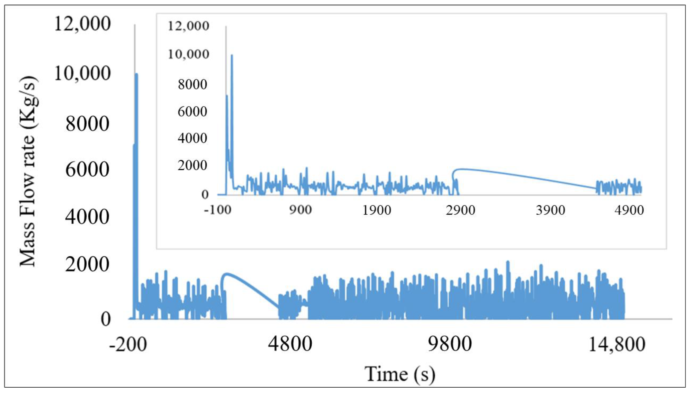
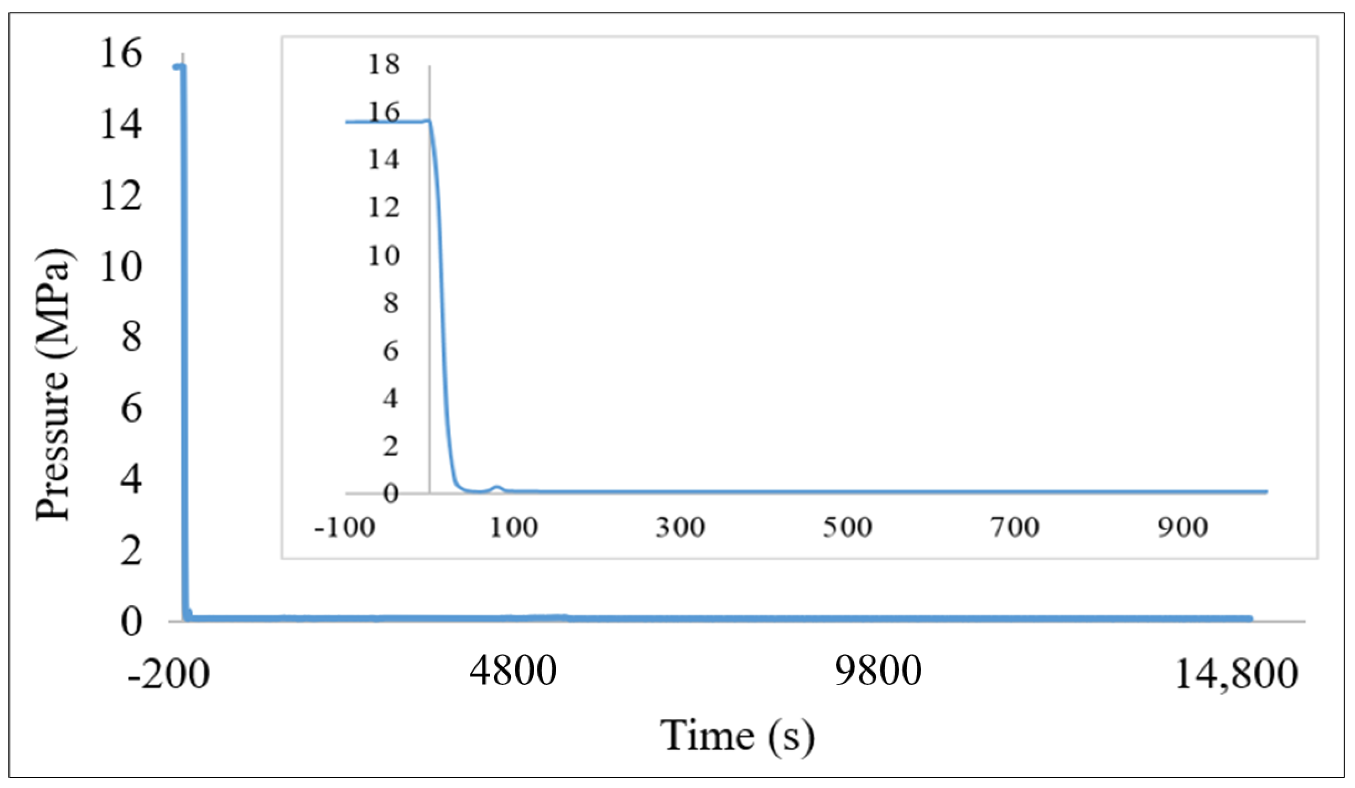
The safety performance of nuclear power plants (NPPs) is a very important factor in evaluating nuclear energy sustainability. Safety analysis of passive and active safety systems have a positive influence on reactor transient mitigation. One of the common transients is primary coolant leg rupture. This study focused on guillotine large break loss of coolant (LB-LOCA) in one of the reactor vessels, in which cold leg rupture occurred, after establishment of a steady-state condition for the VVER-1000. The reactor responses and performance of emergence core cooling systems (ECCSs) were investigated. The main safety margin considered during this simulation was to check the maximum value of the clad surface temperature, and it was then compared with the design licensing limit of 1474 K. The calculations of event progression used the engineering-level RELAP5/SCDAPSIM/MOD3.5 thermal-hydraulic program, which also provide a more detailed treatment of coolant system thermal hydraulics and core behavior. The obtained results show that actuation of ECCSs at their actuation set points provided core cooling by injecting water into the reactor pressure vessel, as expected. The peak cladding temperature did not overpass the licensing limit during this LB-LOCA transient. The primary pressure above the core decreased rapidly from 15.7 MPa to 1 MPa in less than 10 s, then stabilizes up to the end of transient. The fuel temperature decreased from 847 K to 378 K during the first 30 s of the transient time. The coolant leakage reduced from 9945 kg/s to approximately 461 kg/s during the first 190 s in the transient. Overall, the study shows that, within the design of the VVER-1000, safety systems of the have inherent robustness of containing guillotine LB-LOCA.

1. Introduction

All pressurized nuclear power plant (NPP) designs require thorough evaluation to ensure compatibility with existing safety and regulatory standards. Pressurized NPPs should be designed such that, under no credible normal or off-normal situation, can radioactive material be released from the core to the environment [1]. Proper safety measures and continuous analyses ensure that this goal is achieved. Reactor safety analysis helps to improve the environmental indicator used to evaluate the overall sustainability of nuclear energy industry [2]. The primary concern in these analyses is that the large fission product inventory produced in the reactor core is not released in any conceivable accident situation [3]. There are several barriers to such fission product release. The primary barrier is the metal clad of the fuel itself, which isolates the fuel pellets from the coolant [4]. The provision of leak tight “barriers” between the radioactive source and the public are generally three: fuel cladding, the primary system pressure boundary, and the containment [5].
Significant measures have been taken to avoid accidents, but these accidents are still assumed to occur. As such, safety systems, such as emergence core cooling systems (ECCSs), are installed for combating loss of coolant accidents (LOCA) and also to ensure that the reactor’s consequences are under safe limits [6]. The accidents that lead to a severely damaged reactor core are termed as “severe” [7]. Examples are station blackout (SBO) due to total loss of offsite power (LOOP), small, medium, or large break loss of coolant accident (SBLOCA, MBLOCA, or LBLOCA), and failure of ECCS [8]. Severe accident mitigation guidelines (SAMGs) and emergency responses are always needed to contain radioactive release in such accidents [9].
Occurrence possibility of LB-LOCA is low in Water-Water Energetic Reactor 1000 (VVER-1000); however, such an accident may result in catastrophic melting of the reactor core, endangering workers, the public, and the environment. Three Mile Island (TMI) and Fukushima Daiichi nuclear accidents testify to the fact that the operating pressurized NPPs are not immune to these unpredictable occurrences. The introduction of Generation III pressurized water reactor designs, such as VVER-1000, is based on both active and enhance passive engineered safety features. Analysis of safety in the VVER-1000 due to LB-LOCA has an essential role in assessing the times to reach the important set points during the accident progression [10]. System thermal hydraulic codes, such as RELAP5/SCDAPSIM, have a pivotal role in enforcing such thermal hydraulic safety in pressurized NPPs [11]. These codes also guide the development of procedures to mitigate severe accidents if they occur in spite of very low probability (≤10−6). Furthermore, the history of pressurized NPPs shows that the application of system thermal hydraulic codes against the design based accidents (DBA) and beyond design-based accidents (BDBA) is always an obligatory part of licensing, regulation, and operation [12].
With decades of operating experience to draw on, VVER-1000 incorporates proven technologies in a new combination to consolidate the advantages of nuclear power units while increasing safety. Some VVER-1000 are near shutdown for modernization (i.e., oldest VVER-1000, at Novovoronezh) to extend the operating life [6]. This calls for more radiation safety systems analysis as new components are being added to the NPP. There is also a number of VVER 1000 NPP under construction across the globe. African countries (Including Egypt, Ghana, South Africa, Zambia, and Malawi) are willing to construct VVER nuclear power plants in the coming decades with the help of ROSATOM. This is why more safety analysis needs to be done for informed decision on occupation, public, and environmental safety. In this study, VVER-1000 Model V320 pressurized water reactor was investigated. The basic design of this NPP comprises a pressurized water reactor of 3000 MW thermal power with four primary loops.
Therefore, the main objective of this study was to analyze the behavior of the VVER-1000 NPP during a LB-LOCA accident. Additionally, we checked whether the peak cladding temperature would exceed the licensing design limit of 1474 °K (1204 °C) to ensure the integrity of the clad. A Guillotine double-ended LB-LOCA of 850-mm of cold reactor vessel leg, which also connects to the pressurizer, accompanied with an instantaneous total station blackout, was assumed. The selected analyses were performed for the case without any operator intervention using a detailed RELAP5/SCDAPSIM/MOD3.5 model of VVER-1000 and its related reactor ECCSs [13]. The RELAP5/SCDAPSIM/MOD3.5 thermal-hydraulic program uses a two-fluid approach, where three one-dimensional conservation equations are written for both the vapor and the liquid phases.

2. Materials and Methods

2.1. Brief Description of VVER-1000 Reactor

The VVER-1000 NPP is the Russian version of the traditional pressurize water reactor (PWR), as developed in the United States. The earliest designs of VVERs were built before 1970. The first reactor with 1000 MW electrical power was commissioned at Novovoronezh NPP Unit 5 in 1980. The main principles underpinning the VVER-1000 design are maximum use proven technologies, reasonable cost and minimum construction times, balanced combination of active and passive safety systems to manage BDABs, and reduction in the influence of human factors on overall safety [14]. The safety philosophy embodied in the VVER-1000 is unique among reactors on the market, deploying a full range of both active and passive systems to provide adequate fundamental safety functions that should handle complicated situations that go beyond the traditional DBAs [15].

2.2. Layout of the VVER1000 Primary Components

The layout of the primary circuit of a VVER-1000 pressurized water reactor with four coolant loops was symmetrically placed around the vessel. It had a reactor coolant pump (RCP) and a horizontal steam generator (SG) on each loop. The primary pressure maintenance system consisted of a pressurizer (PRZ), surge line, spray line, and a pulse safety facility. The reactor pressure vessel (RPV) had four inlet and four outlet nozzles, and the outlet nozzles were located at elevation rather than the inlet nozzles. The RPV was similar to the one built in the western countries but it had some particularities. The RPV was at a 11.5 m height, and the hot leg’s entrances were located higher compared to the cold leg’s entrances. The distance between the axes was 1.8 m, and the pipes’ diameter was 0.85 m [16].
Four primary coolant loops had a common flow path through the reactor vessel. The downcomer was internally limited by the barrel and at the top by a septum from the hot leg’s entrance. The hot leg’s entrance was separated from the upper plenum by the extension of the barrel, which had holes that allowed the coolant flow. The upper plenum was bounded by a partially pierced cylindrical structure, which had the same geometrical axis as the barrel. It had two functions: first, it held up the upper plenum’s plate and the upper head’s plate; second, it allowed a more uniform flow of the coolant towards the hot legs [6].
The core had an active height of 3.53 m, a flow area of 4.172 m2, and was made of 163 hexagonal fuel elements without a shroud that allowed the cross flow through the core. Each element contained 312 rectangular pins of enriched uranium dioxide. The clad was an alloy Zr-Nb. The pins were placed triangularly in the fuel assembly. The pellets were annular, with an internal diameter of 0.7 mm. There were 61 control elements, each containing 18 B4C pins [17].
The PRZ, which maintained the overall system pressure, compensated the changes in the primary coolant volume. It was connected to the cold leg and hot leg of the primary loop piping by a spry pipeline and a surge line pipeline in one of the loops. The PRZ system was made up of a pressurizer, a condensation tank, a spray system, regulation valves, and electric heaters. There was only one PRZ, which was installed at one of the main loops. It was 11 m in height and had an internal diameter of 3 m and a volume of 79 m3 (55 m3 water and 29 m3 steam) [6].
The SGs were horizontal units, with submerged tube bindles. Each unit included a cylindrical horizontal shell, two vertical nozzles, and U-shaped tubes. On the primary side of the SG were hot and cold header collectors to connect 11,000 small diameter tubes. The coolant coming from the hot leg reached the hot header first and then went through the 11,000 tubes and reached the cold header. From here, it went back to the core, passing through the cold leg. Collectors and tubes were put inside a large amount of water, which represented the secondary side of the steam generator [18]. Their thermal power rating was 750 MW and produced steam at 278.5 °C and 6.28 MPa.
All VVER-1000 NPPs had ECCSs of four accumulators, two of which injected directly into the reactor pressure vessel’s downcomer and the other two into the upper plenum of the RPV. In addition, there were emergency injection systems comprising four high pressure loops (HPIS), one for each main loop, and four low pressure systems (LPIS), two of which inject into the RPV’s downcomer and the other two into the upper plenum. The plant had a containment system made of reinforced concrete with an internal cylindrical hermetic vessel (45 m diameter and 54 m height) and a spray system to condense steam [19].

2.3. LARGE LOCA Accident Analysis in VVER-1000

The LB-LOCA involved a breach of a single large loop pipe in primary coolant system (PCS), either from the inlet or outlet side. Guillotine was assumed to be a double-ended rupture of pipe above 85 cm (33 inches). The PCS was rapidly depressurized by the LOCA blowdown, and the reactor was scrammed by the rapid safety response. The rate of blowdown from the PCS was within the design capacity of the reactor containment. As pressure began to rise in the localization volume, operation of the ventilation system was terminated and the localization volume was isolated. The spray system was automatically actuated and sprayed into the containment via three concentric spray headers in the containment dome [2].
The ECCS pumps were automatically started as PCS pressure drops. At a pressure of 6.0 MPa (870 psi), the accumulators began discharging borated water into the reactor vessel. The rapid depressurization of the PCS caused the accumulators to be the first source of makeup water to reach the PCS [20]. The high pressure dropped (later) to low pressure, and ECCS pumps were able to provide makeup. When the borated water storage tanks used by the ECCS and the spray pumps were depleted, the suctions of the ECCS and spray pumps were realigned to the containment sumps. This created a re-circulation flow path that could provide long-term makeup to the PCS [21,22].

3. RELAP/SCDAPSIM in Nuclear Power Plants

The RELAP5/SCDAPSIM/MOD3.5 computer code was designed to predict the behavior of pressurized water reactor systems during normal operations and accidents (Job and Code, 1995). The RELAP5 models calculated the overall RCS thermal hydraulic response, control system behavior, reactor kinetics, and the behavior of special reactor system components, such as valves and pumps. The SCDAP portion modelled the behavior of the core and vessel structure under normal and accident conditions [23]. This included debris and molten pool formation, debris/vessel interaction, and the structural failure (creep) of the vessel structure during severe accidents [7]. Therefore, RELAP5/SCDAPSIM/MOD3.5 is one such system thermal hydraulic code that can be applied to understand both DBAs, as well as LB-LOCA and SBO accidents [6].

Qualification of RELAP5/SCDAPSIM/MOD3.5 as a Computational Tool

A key feature of the activities performed in NPP safety technology was constituted by the necessity to demonstrate the qualification level of each computation tool adopted within an assigned process and of each step of the concerned process [24]. RELAP5/SCDAPSIM/MOD3.5 thermal-hydraulic program had the capability to predict relevant phenomena occurring for the selected spectrum of accidents and the relevant phenomena occurring for the selected spectrum of the accidents, reproduce peculiarities of the reference VVER-1000 plant, and produce suitable results for a comparison with the acceptable criteria of the VVER-1000. These available requisites, which are accessible in the RELAP5/SCDAPSIM/MOD3.5 thermal-hydraulic program, enabled it to qualify for this study.

4. Research Accident Scenario Description and Modelling

4.1. The Event Causes and Identification

A Double-Ended LOCA (DE-LOCA), also called a Guillotine Break (ID-850 mm), between the MCP and reactor nozzle was assumed. With a cold reactor vessel pipeline rapture, coolant was injected through the leak, and a decrease in the primary pressure and coolant mass in the reactor occurred. The specified accident could be identified from the following symptoms: reactor coolant pressure decrease, PRZ level decrease, and containment pressure increase. The analysis was performed without considering the operator’s actions on the reactor accident management. Safety systems provided in the design ensured reactor shutdown due to scram system actuation.

4.2. Interpretation of the LB-LOCA Scenario in VVER-1000

In the case of LB-LOCA, the ECCS was in charge of averting the consequences of losing the primary coolant and confined conditions in the margins of a DBA. The ECCS active parts of HPIS and LPIS, as well as the passive parts, are available in VVER-1000 [20]. This availability resulted in the ability of core cooling in the long term during the reactor transient. If the operator action was not performed, passive parts of ECCS, i.e., accumulators and KWU tanks, were the only available systems that could inject water into the primary circuit as a safety precaution.
In this scenario, pipe break size determines the accident progression, especially pressure decrease, which regulates the intervention of ECCSs [25]. Unless proper measures are taken, fuel and fuel rod cladding heating up can occur, with their subsequent core melting down. Reactor safety systems provided the reactor with a safe shut-down and post-transient core cooling, and the reactor plant readjusted to a safe mode. Reactor power decreased from the 3000 MWth to the decay heat level within the reactor core. Primary coolant leaks compensation and core cooling during LBLOCA was supplied by ECCS [17].
Accumulators supplied boric acid solution into the reactor for cooling when primary pressure decreased lower accumulator gas pressure [26]. There were four accumulators; two were connected to the downcomer and the other two to the reactor upper plenum. The LPIS and HPIS are meant for reactor core heat removal after reactor shutdown and under the conditions for which heat removal through steam generators is inefficient (low primary parameters) or impossible (loss of primary coolant). HPIS is an emergency high pressure boron injection sub-system comprising boron emergency supply pumps, pumps to borated water accumulators connecting pipelines, and appropriate valves. LPIS is a decay heat removal low pressure sub-system comprising borate water storage tanks, primary emergency pumps, pumps to sump and tanks, connecting pipelines, and appropriate valves [17].

4.3. Plant Geometrical Modelling

The RELAP5/SCDAPSIM/MOD3.5 input was divided into four distinct areas: hydrodynamics, heat structures, control systems, and neutronics. The model for this study was mainly composed of hydrodynamic components. These represented the parts of the VVER-1000 reactor, where coolant passed through and heat structures represented solid parts of the reactor. All vessel walls and plates presented in the core to maintain the assemblies and the integrity of the pressure vessel and the core barrel were modelled with heat structures. Furthermore, the cold and hot leg piping, steam generator tubes and shells, pump suction, and piping was represented by heat structures. Figure 1 below represents a VVER-1000 nodalization used in this study.
The RPV model was composed of down-comer, lower and upper plenum, upper and lower heads, core flow, and a bypass channel. The core active region was divided into two channels. It was composed of a down-comer connecting to the lower plenum. The fueled parts of the core comprised five channels and a bypass region. Each channel was further divided into 10 axial control volumes. Fuel rods were represented by heat structures attached with each axial control volume in average and a hot channel. Each volume of these channels was connected to the respective outer channel using cross flow junctions. Hot and cold channels of the primary side of the steam generations were represented by pipes, each with 5 volumes and associated heat structures.
The four main RCPs were modelled as specific components, with the coast down curve provided for in the VVER-1000 design. The three cold legs (108, 208, 308) of steam generators, 1 to 3, were modelled using a pipe component divided into four volumes, while two cold legs from steam generator number 4 (408 and 409) were modelled using a pipe component divided into two volumes. The cold leg pipes were connected to downcomer, which connected to the lower plenum to complete the loop.
The secondary side was modelled using a RELAP5/SCDAPSIM/MOD3.5 pipe component with five vertical volumes. The first four represented the riser, while the fifth represented the transition region. Each SG model had a separator. The action of safety pressure operated relief valves (PORV) was controlled by open trips 561 and close trips 562, respectively, in the input desk. The feed and steam valves were controlled by RELAP5/SCDAPSIM/MOD3.5 feed and steam control variables. Single inlet branch 450 collected steam from the four SG’s and connected to the turbine volume 469 via a motor valves (mtrvlv) control valve 486, then the steam went into the mean steam line time-depended volume (tmdpvol) 480 via a gov servo valve.
The PRZ was modelled as a pipe component with 10 volumes. The spray line was connected to the steam dome from cold legs in loop 4. The steam dome was a separate branch component. The heater was modelled as a 1 d heat structure and transferred heat to the bottom volume of the pressurizer. The PRZ surge line and the hot and cold leg piping were constructed of stainless steel. The power operated relief valves (PORV) were located at the top of the pressurizer and could be used to relieve excess pressure in the reactor coolant system (RCS). PRZ safety relief valves (SRVs) were also available to handle pressure excursions in excess of the pressurizer PORV capacity. Three valves connected the tank to a containment represented by a single volume. The bottom volume of the pressurizer then connected to the hot leg using a surge line, which was modelled as pipe component.

4.4. Nodalization of Safety Systems

The model included four independent accumulator sub-system components (volumes 610, 620, 630, and 640). Two of them (610 and 630) were connected to the reactor upper plenum 1 via valves, 631 and 611, while the other two (620 and 640) were connected to the downcomer via valves, 621 and 641, as seen in Figure 2.
Hydraulic cards 800 simulated HPIS. The nodalization had three sets of borated water storage tanks; 810, 820, and 830 connected to cold leg 1 (108), cold leg 2 (208), and cold leg 3 (308), respectively. Between the tanks and the cold legs, there were high-pressure injection pumps, 811, 821, and 831. The HPIS tanks were represented as time-dependent volume.
Cards 700 were for LPIS. There were three sets of low-pressure injection pumps, 711, 721, and 731, and borated water storage tanks, 710, 720, and 730. Pump 711 took borated water from tank 710 and pumped it into pipes form ACC 610 and ACC 620; whereas pump 721 took borated water form tank 720 and pumped it into pipes from ACC 630 and ACC 640. Tank 730 was connected to cold leg 308 and hot leg 400 via valves 732 and 733, respectively. The LPIS tanks were represented as time-dependent volume.
The first line of the overpressure protection system was modelled as relief valves, which were connected from the PRZ upper head to relief tanks. The second stage of the overpressure protection system was modelled by a spray line with a spray valve. This spray line connected from cold leg through up to a spray volume. In addition, valve 349 was connected from hot leg 100 (roh1) of loop 1 to a time-dependent volume. SG safety valves were connected from the end of the first part of steam lines to time-depended volumes.

4.5. Nodalization Qualification

It was necessary to define a procedure to qualify the nodalization used in this research in order to obtain qualified (i.e., reliable) calculated results. A major issue in the use of mathematical models, such as the RELAP5/SCDAPSIM/MOD3.5 thermal-hydraulic program, is constituted by the model capability to reproduce the plant behavior under steady-state and transient conditions [27]. These aspects constituted two main checks, for which acceptability criteria had to be defined and satisfied during the nodalization-qualification process report [28]. The first was related with the geometrical fidelity of the nodalization of the VVER-1000; the second was related to the capability of the code nodalization to reproduce the expected transient scenario. The checks about the nodalization were necessary to take into account the effects of several different sources of approximations. From the available data, an approximated nodalization (based on the code guidelines) of the plant reduced the level of detail. During the study, the RELAP5/SCDAP/MOD3.5 thermal-hydraulic program was capable of reproducing the hardware, the plant systems and the actuation logic of the systems, hence, further reducing the levels of details of the nodalization. Checking the capability of the RELAP5/SCDAP/MOD3.5 nodalization qualified the transient analysis, which took into effect the following considerations: a) The thermal-hydraulic program options must be adequate; b) the nodalization solutions must be adequate.

4.6. LOCA Modelling

Figure 3 shows the cold tube rupture modelled for this study. If a tube is ruptured, primary coolant could flow into the containment side. In order to simulate this situation, a valve (trip valve) junction connecting a primary side pipe and a secondary side containment were introduced. In the modelling, the break size for a hot leg of 850 mm was assumed (0.56745 m2). The break sizes were controlled by changing flow areas of the triple valves number 606 and 607. A tube rupture simulation was started by opening or closing the valve junction (461) at a steady state.

4.7. Initial and Boundary Conditions

An initial condition of the VVER-1000 and the scenario conditions (boundary conditions) in primary coolant leakage transient were chosen on the basis of the following general conservative assumptions: (1) The VVER-1000 corresponds to the most unfavorable combination of deviations of regime parameters within the limits of the measurement and accuracy error of their control. (2) The values of set points with uncertainty stipulate a negative influence on the accident consequences in the reactor.

4.8. Steady State Qualification Level

The ‘stead state’ qualification level included different checks. The first was related to the evaluation of the geometrical data and numerical values implemented in the nodalization. The second was related to the capability of the nodalization to reproduce the steady-state qualified conditions. The steady-state conditions were determined using a determined set of relevant parameters that unequivocally identify the VVER-1000 plant state (e.g., temperatures, pressure, flow rate levels). The first check was performed by an independent researcher. In the second check, a steady state calculation was performed, which was constituted by a ‘null transient’ calculation (no variation of relevant parameters occurred during the calculation).

4.9. Transient Qualification Level

Transient qualification level was necessary during the study to demonstrate the capability of the code nodalization to reproduce the relevant thermal-hydraulic phenomena expected during the transient. This step also permitted us to verify the correctness of some safety systems that were in operation only during transient events. Both qualitative and quantitative were established to express the acceptability of the transient calculation. Two different aspects were employed, and the code input dealt with the nodalization of an integral reactor. In this case, the code calculation was used for the code assessment. Checks included the code options for selected logic of some systems (e.g., ECCSs). The objective of the code calculation was constituted by the analysis of a transient in VVER-1000. In this case, it was necessary to check the nodalization capability to reproduce the expected thermal-hydraulic phenomena occurring during the transient calculation, the selected code options, the adopted solutions for the development of the VVER-1000 nodalization, and the logic of the systems not involved in the steady-state calculation.

5. Results and Discussion

5.1. Model Validation

It is required that NPP safety analysis codes should be validated—that is, a true representative set of calculations should be tested against measured or otherwise acceptable data. Therefore, validation was done to ensure completeness and correctness of the code used for this research. It represented an exact plant geometrical fidelity with its described operating system and conditions, logic and characteristic of the measurement systems, and other relevant hydraulic parameters. It also reproduced the nominal measured steady-state condition of normal operating systems. Those calculated during the steady-state execution of the computer program were within the design uncertainty band. This confirmed that the system had reached the steady state. This was achieved after a complete analysis of the interaction between the involved systems and the control and interaction process on the initial condition. Lastly, it showed a satisfactory behavior in time-dependent conditions. The stage fell in transient validation or final qualification.

5.2. Study Steady State Results

The steady state analysis of the VVER-1000 reactor was performed in the RELAP5/SCDAPSIM/MOD3.5 thermal-hydraulic program with the model, as described in Section 4 of this document. During simulation, required equipment of the VVER-1000 NPP, such as MCPs, pipelines, SG, and PRZ, was modelled. At the end of the nodalization of the VVER-1000 plant, it was necessary to understand the commencement and boundary conditions, which ought to be as close to the conditions of the real plant as possible, before simulating the behavior during the accident. This helped to qualify the nodalization in order to obtain credible calculated results. To attain all these conditions, a preliminary calculation, called the steady state calculation, was made. A standard qualification procedure was provided for the verification of the steady-state condition results by thermal-hydraulic system codes in the reactor safety, which included an acceptable error for modelling values [25]. With this procedure, the steady-state results were verified for the VVER-1000 model. After this, the RELAP code ran for a while until the values of the main variables were stabilized around their nominal values. In the simulation. the stationary calculation lasted for 100 s. The comparison of the design parameter values with calculated steady state results with RELAP5/SCDAPSIM/MOD3.5. were close to each other. The comparison showed that the modelling results were within the acceptable limits. These steady-state results were convincing enough to perform transient analyses using the same model with the RELAP5/SCDAPSIM thermal-hydraulic program.

5.3. Analysis of the RELAP5/SCDAPSIM/MOD3.5 Results

The LB-LOCA of the 850 mm transient was 0 s after a stable steady state condition. The progression of the accident, along with the reactor degradation parameters, are shown in Table 1. The results from the research are presented in Figures 4–13. Following the double-ended guillotine rupture (100% break) in one of the cold legs, the pressure of the primary circuit sharply dropped as a result of a large water inventory loss in the PCS, and the water level in the PRZ also sharply decreased. After the reactor tripped, the turbine also tripped, which followed instantly. The core power decreased to below 100 MW thermal soon after the scram-signal, then the power became stable 100 s into transient until the end of the RELAP5/SCDAPSIM/MOD3.5 simulation. The responses fell within the accepted range of FSAR.
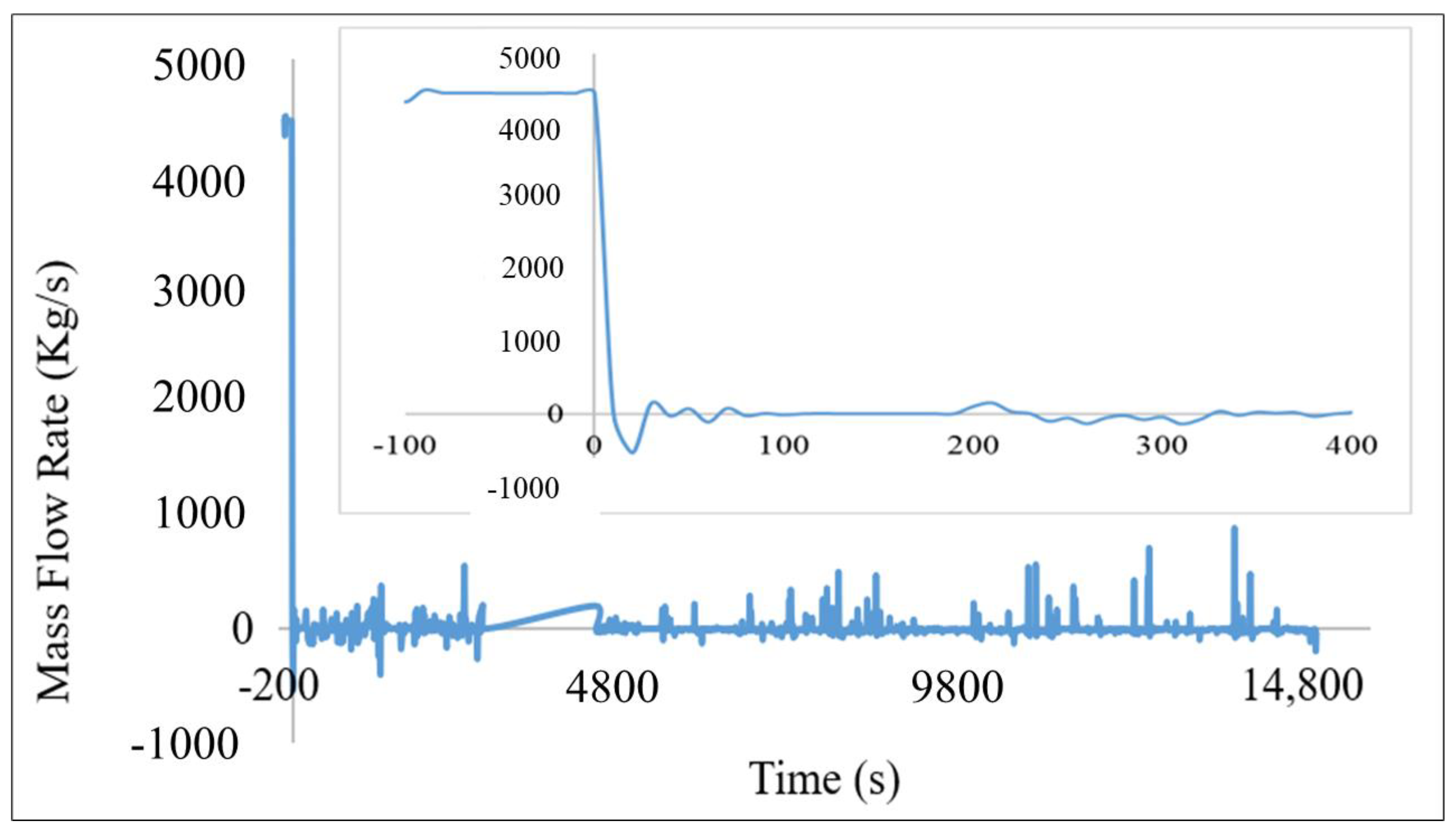
The scram signal was generated with a delay of 1.6 s from the incidence of the transient. Coolant gashed out of the RCS through the broken area, with the highest flow rate up to a value of 25,838.35 kg/s in t = 0 s (at breaking time). At 90 s into the accident, the coolant flow rate sharply dropped to 484 kg/s and continued to fluctuate until the end of the simulation, as shown in Figure 4. Coolant flow rate at the core inlet rapidly decreased from 4488 kg/s to 16 kg/s in less than 10 s, as indicated in Figure 5. The flow rate was mainly dependent on the pressure in the primary circuit and from flashing through the ruptured area. Injection of cold borated water from ECCSs quenched the void in the RPV and reduced their coolant temperature continuously.
At the time of cold leg rupture, the outlet primary pressure increased, then it sharply dropped in less than 10 s, as shown in Figure 6. The broken cod leg depressurized faster than unbroken legs of RPV. The reactor primary pressure performance was similar in both analyses of RPV and PRZ.
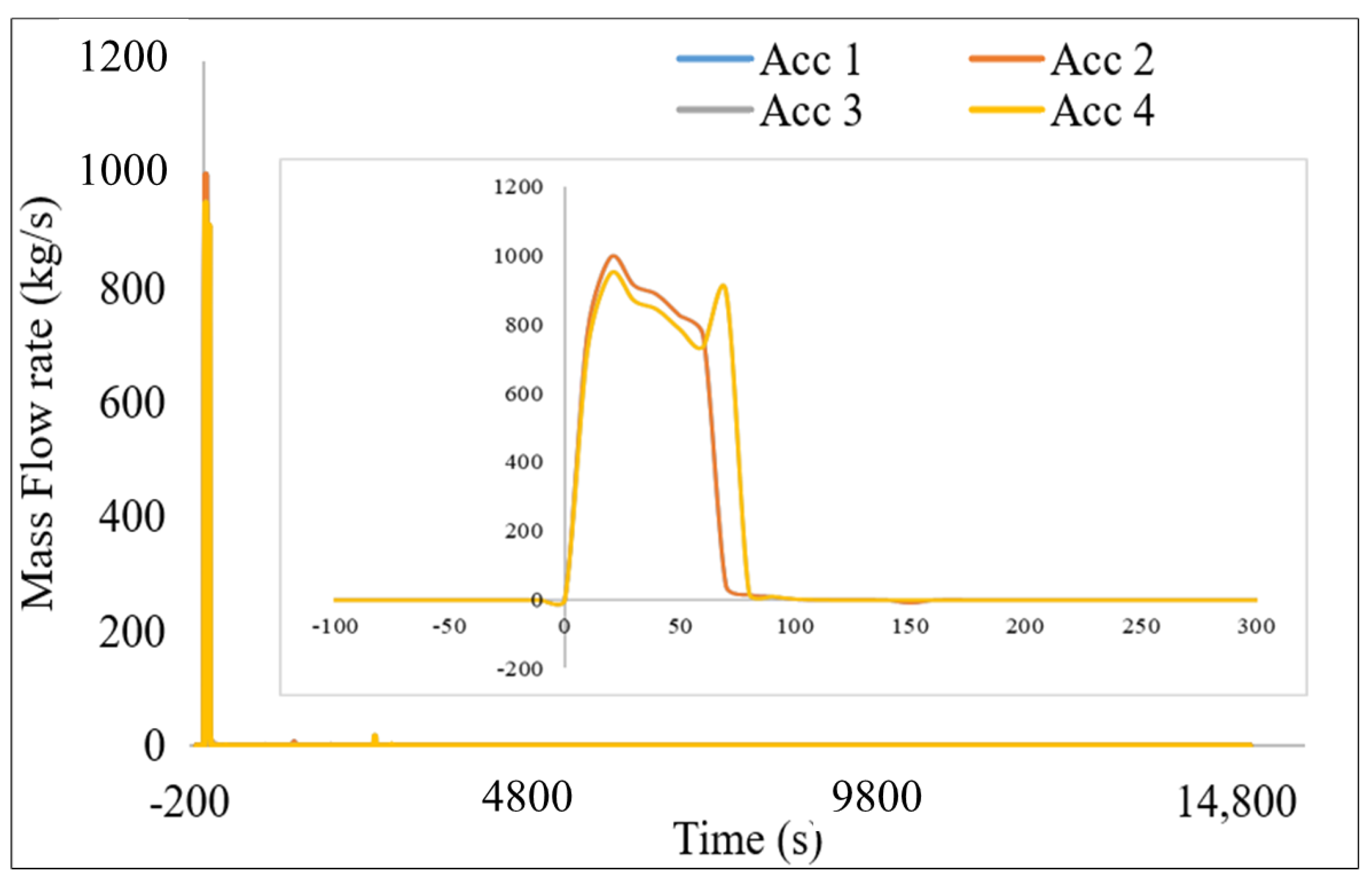
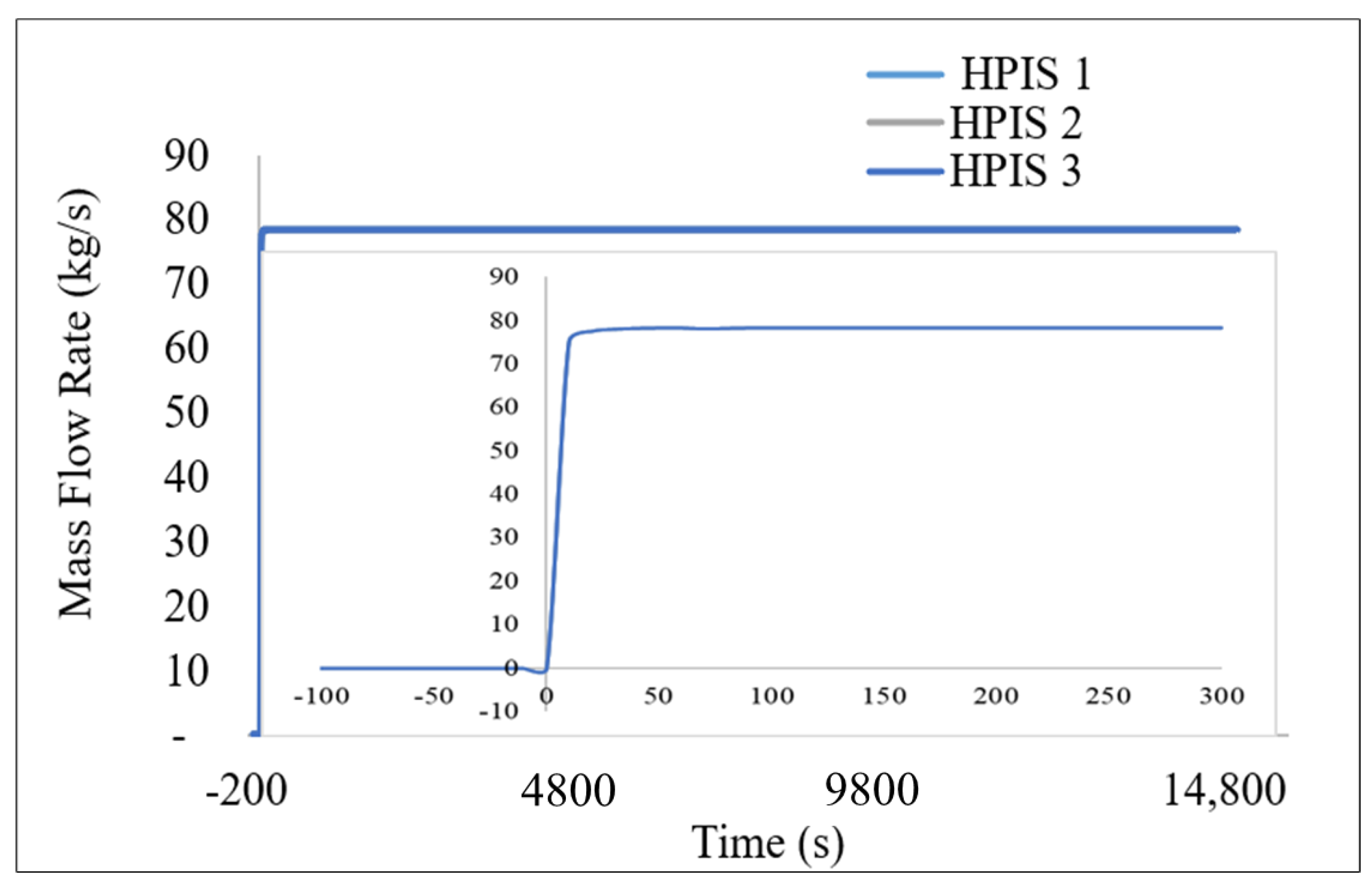
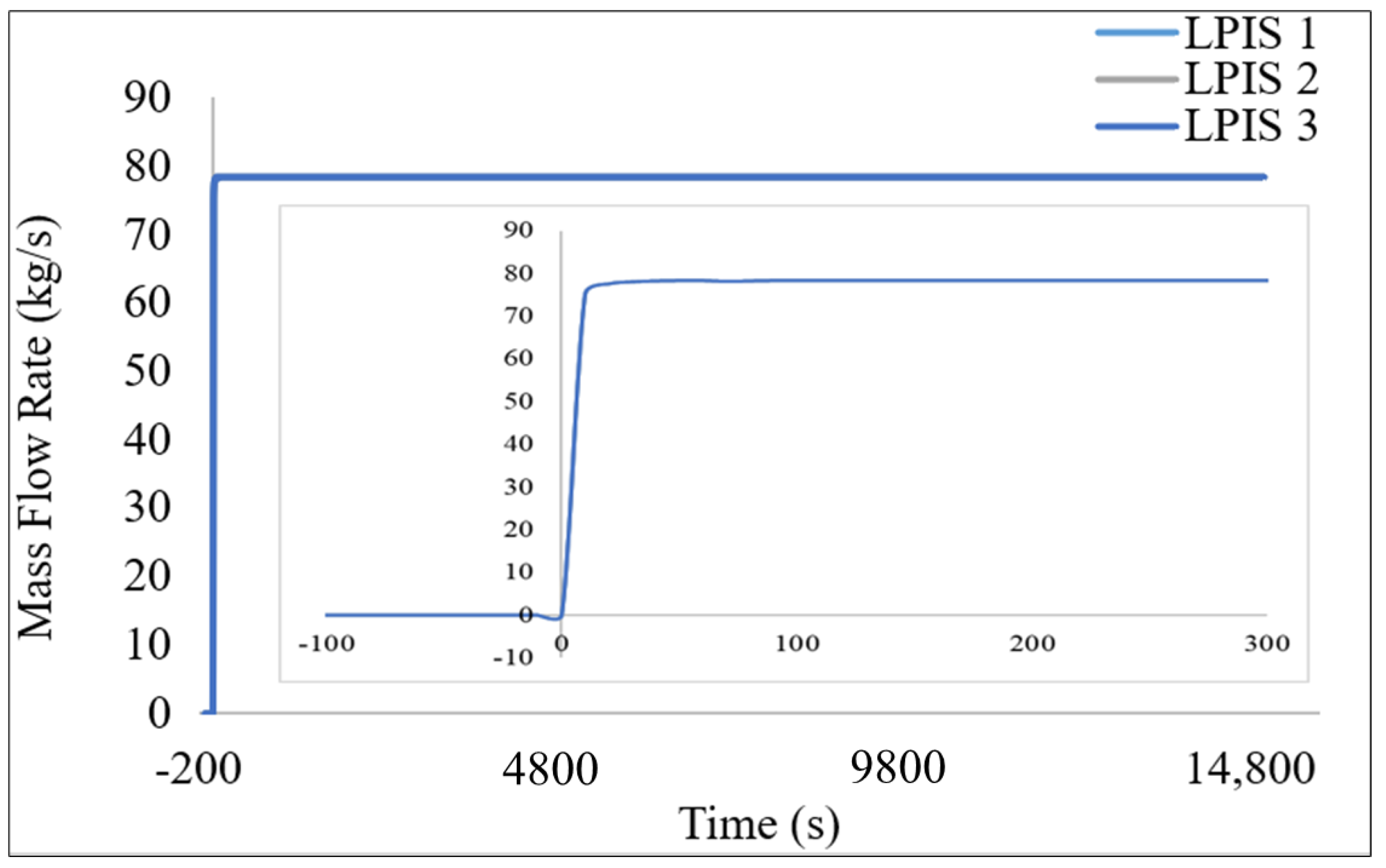
From the onset of the accident, the primary pressure dropped down sharply (see Figure 7). When it dropped below 6.0 MPa (870 psi), all four accumulators ACCs started to provide water into the reactor pressure vessel and direct vessel injection lines, respectively, followed by HPIS and LPIS. All the ECCS were activated after the scram signal, providing a relatively high flow of borated water to the primary loops and upper plenum. For accumulators, the injection commenced in 8.5 s. The injection flow rate increased up to 826 kg/s after 50 s into LOCA. Thereafter, injected borated cold water rate of flow decreased until all accumulators run out of water, as shown in Figure 8. Once HPIS injection commenced (10 s into LOCA), it provided coolant at a flow rate of 78.4 kg/s until the end of the run, as depicted in Figure 9. The actuation of the LPIS proceeded in 13 s, with a delivery of coolant of 78.4 kg/s up to the end of the simulation, as indicated in Figure 10.
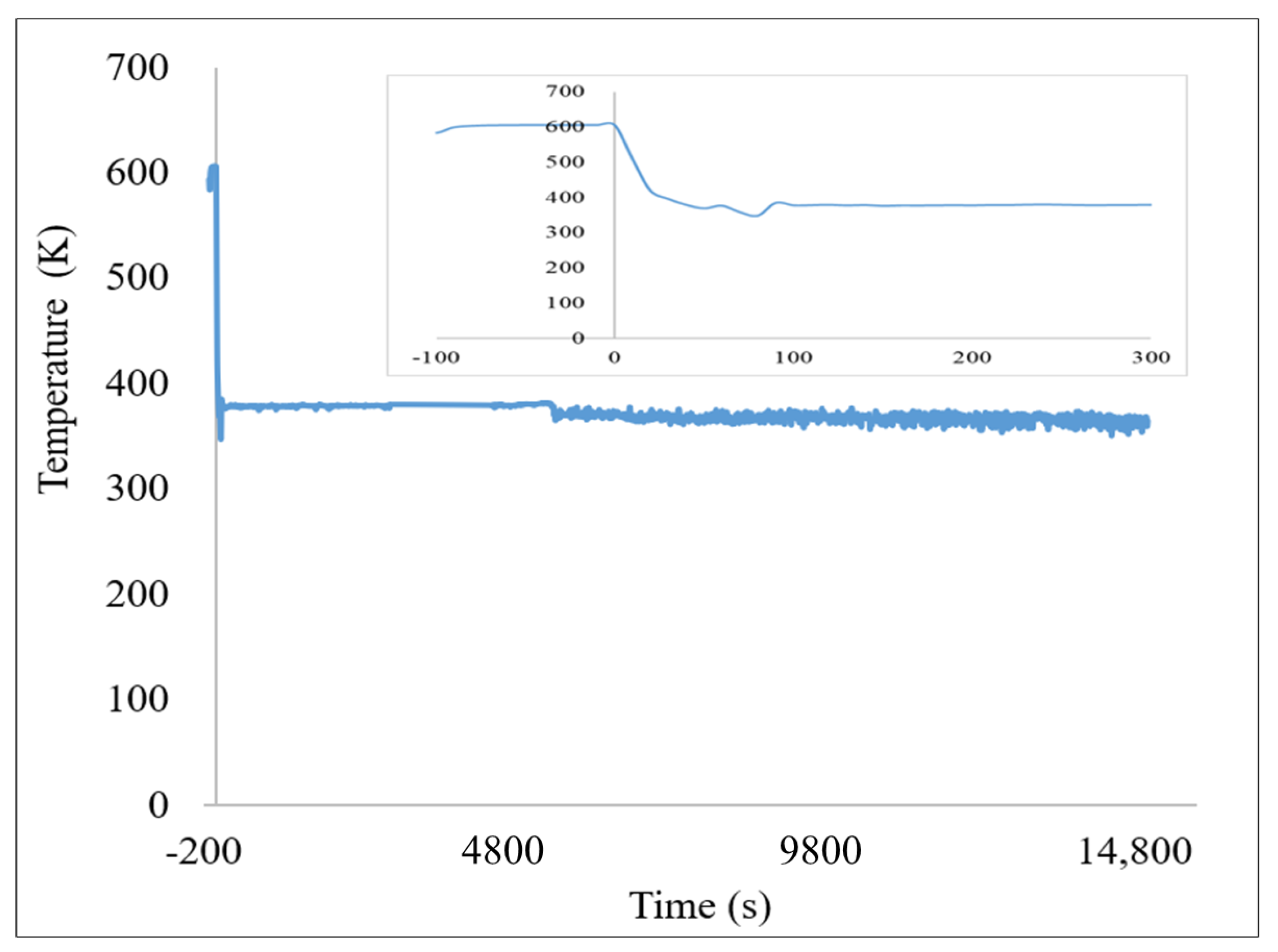
Before the ECCS actuation, 10 s into the transient, the fuel temperature increased up to 850 K (576.85 °C) for a short period. Soon after the ECCS commenced to inject the coolant, the fuel temperature dropped, as illustrated in Figure 11. This underscores the importance of passive and active safety systems in VVER-1000 NPPs. ECCSs are reliable to mitigate or delay core damage during LOCA transient conditions. The fuel temperature then stabilized around 400 K and started to cool slowly up to the end of simulation. No fuel damage was observed.
The temperature of the fuel cladding is presented in Figure 12. Following LB-LOCA, high void formation and low core flow resulted in a rise in clad temperature. The source of heat generation after the scram signal was based on fission products decay from the reactor core. The cladding temperature increased suddenly to about 840 K (566.85 °C) a few seconds after LOCA incitation. The observed rise in fuel and cladding temperature might be due to a strong negative temperature feedback effect in the fuel, since the reactivity increased with decreasing fuel temperature, causing the onset of fission and therefore power generation again.
The cold water from injected loops and upper plenum quenched and expelled part of the void of the reactor core and prevented superheating of the coolant, which, in turn, reduced cladding temperature. This evaded the cladding temperature, reaching the peak design limit of 1474 K (1200.85 °C).
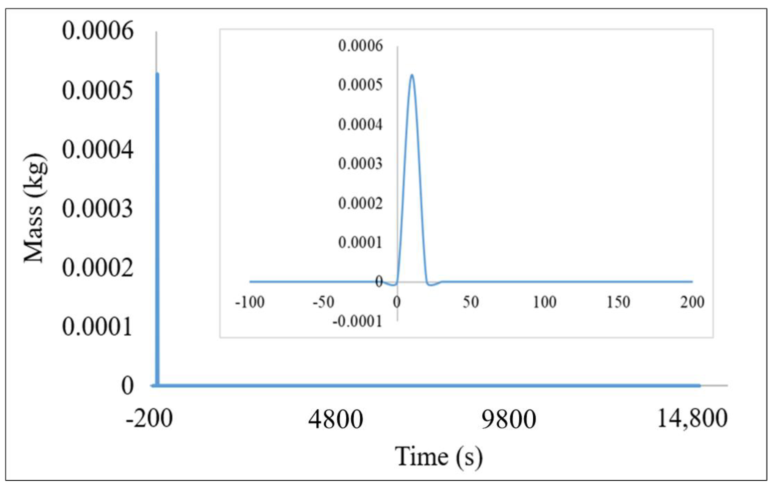
The rapid depletion of coolant in the reactor core led to core heating up to the actuation of ECCSs. Small amounts of hydrogen were produced from a mixture of zirconium, iron, and B4C oxidation with the available steam. After attaining conditions for the steam-zirconium reaction, the maximum generation of hydrogen (see Figure 13) was found at 10 s, amounting to 0.00057 kg. After the commencement of ECCSs, no amounts of cumulative hydrogen produced were recorded.

6. Study Novelty

The LOCA in VVER 1000 was extensively studied in various safety research papers. However, these studies were focused on reactor safety for small break LOCA during the first 100 s after the initiation of the transient through the verification of safety parameters, such as clad temperature, onset of nucleate boiling, and flow instability. Limited work has been done for extended times beyond 100 s and for LB-LOCA. Performance assessment of the cod leg that connects to the pressurizer against the MB-LOCA or LB-LOCA scenario to identify the vulnerable break size that threatens the safety functions has not been fully covered. This paper focused on the coolability of the reactor over a prolonged period, >100 s, after the beginning of the transient due to LB-LOCA (850 mm). This study adds literature to VVER 1000 behavior due to the PRZ cold leg rupture. The transient time is extended to 15,000 s to permit the code to predict any expected or unexpected phenomenon in core cooling. The RELAP5/SCDAPSIM/MOD3.5 thermal-hydraulic program has not been used for such a localized LB-LOCA accident before. This underscores the novelty of this study. Furthermore, this study may be used, as deemed necessary, for upgrading the water inventory or reassessing safety systems of operating VVERs, modifications of the safety systems of newly designed reactors and Gen IV reactors, and preparation of major core safety significance for Gen V and small modular reactors.

7. Conclusions

This study focused on the analysis of the post-accident transient performance behavior of VVER-1000. The accidental transient studied was a guillotine double-ended break in the cold leg of the reactor vessel with the RELAP5/SCDAPSIM/MOD3.5 thermal-hydraulic program. The code was used to observe responses of reactor transient and its timing through the reactor trip and all the main events thereafter. The main output parameter considered was the evolution of cladding temperature. Reactor pressure dropped sharply due to a sudden cold loop rupture and coolant gushing initiation. The reactor core coolant blowdown resulted in coolant flow reversal through the PRV. These occurrences caused a peak of the fuel and clad temperature a few seconds into the accident. The peak was due to the deterioration of heat removal in the core, caused by stagnation of the coolant, flow reversal, and release of the heat stored from the fuel rods. However, this temperature peak decreased when the core was cooled by the actuation of the ECCSs. The RELAP5/SCDAPSIM/MOD3.5-predicted maximum rod surface temperature did not reach the licensing threshold of 1474 K (1200.85 °C). This was achieved by interventions of ECCSs. The reactor core maintained its integrity with an adequate injection of core coolant from ECCSs. The reactor was found to have a good performance in mitigating the consequence of LB-LOCA in the cold leg. These findings could act as a stimulus for future endeavors that would enhance the safety performance of advanced NPPs.

Author Contributions

Conceptualization, F.G.D.T.; methodology, F.G.D.T., A.E. and M.H.M.H.; software, F.G.D.T. and A.E.; validation, A.E.; formal analysis, F.G.D.T. and A.E.; writing—original draft preparation, F.G.D.T.; visualization, F.G.D.T., A.E. and M.H.M.H.; manuscript language editing, F.G.D.T., A.E. and M.H.M.H. All authors have read and agreed to the published version of the manuscript.

Funding

This research received no external funding.

Institutional Review Board Statement

Not applicable.

Informed Consent Statement

Not applicable.

Data Availability Statement

Data presented in this article is available on request from the corresponding author.

Acknowledgments

The authors would like to thank IAEA-AFRA and the Nuclear and Radiation Department of Alexandria University for support rendered towards the study. The authors also thank Innovative Systems Software (ISS) and Chris Allison for providing the VVER-1000 input, and the regional training centre for letting us use RELAP5/SCDAPSIM/MOD3.5. Lastly, we would like to thank Mohosen Salehi and Amb. Caroline C. S. Bwanali and Chifundo Tenthani for their sincere help and advice in making the nodalization of the VVER-1000 and manuscript editing.

Conflicts of Interest

The authors declare no conflict of interest regarding the publication of this paper.

References

  1. Kim, J.; Park, S.Y.; Il Ahn, K.; Yang, J.E. IROCS: Integrated accident management framework for coping with beyond-design-basis external events. Nucl. Eng. Des. 2016, 298, 1–13. [Google Scholar] [CrossRef]
  2. Gjorgiev, B.; Volkanovski, A.; Sansavini, G. Improving nuclear power plant safety through independent water storage systems. Nucl. Eng. Des. 2017, 323, 8–15. [Google Scholar] [CrossRef]
  3. International Atomic Energy Agency. IAEA SAFETY STANDARDS SERIES Safety of Nuclear Power Plants: Design; International Atomic Energy Agency: Vienna, Austria, 2000; Volume NS-R-1. [Google Scholar]
  4. Kurakov, Y.A.; Dragunov, Y.G.; Fil, N.S.; Krushelnttsky, V.N.; Berkovich, V.M.; Federation, R. Improvement of operational performance and increase of safety of WWER-1000/V-392. In Proceedings of the Technical Committee Meeting on Performance of Operating and Advanced Light Water Reactor Designs, Munich, Germany, 23–25 October 2000; IAEA: Vienna, Austria, 2001; pp. 143–154. Available online: https://www.osti.gov/etdeweb/biblio/20198946 (accessed on 10 October 2021).
  5. International Atomic Energy Agency. Accident Analysis for Nuclear Power Plants with Pressurized Water Reactors; Safety Reports Series No. 30; International Atomic Energy Agency: Vienna, Austria, 2003; p. 65. [Google Scholar]
  6. International Atomic Energy Agency. Assessment of Defence in Depth for Nuclear Power Plants; Safety Reports Series No. 46; International Atomic Energy Agency: Vienna, Austria, 2005. [Google Scholar]
  7. ARIS. Status Report 93-VVER–1000; ARIS: Vinenna, Austria, 2011; Volume 1000. [Google Scholar]
  8. Kumar, A. Application of RELAP/SCDAPSIM for Severe Accident and Safety Analysis of Nuclear Reactor Systems. Ph.D. Thesis, Indian Institute of Technology New-Delhi India, Kanpur, India, 2016. [Google Scholar]
  9. Borisov, E.; Grigorov, D.; Mancheva, K. Study of long-term loss of all AC power supply sources for VVER-1000/V320 in connection with application of new engineering safety features for SAMG. Ann. Nucl. Energy 2013, 59, 204–210. [Google Scholar] [CrossRef]
  10. Mohsendokht, M.; Hadad, K.; Jabbari, M. Reducing the loss of offsite power contribution in the core damage frequency of a VVER-1000 reactor by extending the house load operation period. Ann. Nucl. Energy 2018, 116, 303–313. [Google Scholar] [CrossRef]
  11. Volkanovski, A.; Prošek, A. Extension of station blackout coping capability and implications on nuclear safety. Nucl. Eng. Des. 2013, 255, 16–27. [Google Scholar] [CrossRef]
  12. Jabbari, M.; Hadad, K.; Pirouzmand, A. Re-assessment of station blackout accident in VVER-1000 NPP with additional measures following Fukushima accident using Relap/Mod3.2. Ann. Nucl. Energy 2019, 129, 316–330. [Google Scholar] [CrossRef]
  13. Pavlova, M.P.; Groudev, P.P.; Stefanova, A.E.; Gencheva, R.V. RELAP5/MOD3.2 sensitivity calculations of loss-of-feed water (LOFW) transient at Unit 6 of Kozloduy NPP. Nucl. Eng. Des. 2006, 236, 322–331. [Google Scholar] [CrossRef]
  14. Yousif, E.; Zhang, Z.; Tian, Z.; Ju, H.R. Simulation and Analysis of Small Break LOCA for AP1000 Using RELAP5-MV and Its Comparison with NOTRUMP Code. Sci. Technol. Nucl. Install. 2017, 2017, 4762709. [Google Scholar] [CrossRef] [Green Version]
  15. Dwiddar, M.S.; Badawi, A.A.; Abou-Gabal, H.H.; El-Osery, I.A. From VVER-1000 To VVER-1200.Investigation of the Effect of the Changes in Core. In Proceedings of the PHYTRA 3—The Third International Conference on Physics and Technology of Reactors and Applications, Tetouan, Morocco, 12–14 May 2014. [Google Scholar]
  16. Vojackova, J.; Novotny, F.; Katovsky, K. Safety analyses of reactor VVER 1000. Energy Procedia 2017, 127, 352–359. [Google Scholar] [CrossRef]
  17. Heralecky, P. International Agreement Report: Post-Test Analysis of Upper Plenum 11% Break at PSB-VVER Facility Using TRACE V5.0 and RELAP5/MOD3.3 Code; US Nuclear Regulatory Commission: Rockville, MD, USA, 2014. Available online: https://www.tes.eu/wp-content/uploads/2019/06/Post-test-Analysisof-Upper-Plenum-11-Break_PSB_VVER_TRACE_RELAP.pdf (accessed on 10 August 2021).
  18. Tarantino, M.; Auria, F.D.; Giorgio, G. Simulation of a large break loca on VVER-1000 npp by RELAP5/MOD3 2 simulation of a large break loca on VVER-1000 NPP. In Proceedings of the ANS/HPS Student Conference Nuclear Engineering, Texas A&M University, College Station, TX, USA, 29–31 March 2001. [Google Scholar]
  19. Pirouzmand, A.; Ghasemi, A.; Faghihi, F. Safety analysis of LBLOCA in BDBA scenarios for the Bushehr’s VVER-1000 nuclear power plant. Prog. Nucl. Energy 2016, 88, 231–239. [Google Scholar] [CrossRef]
  20. Tabadar, Z.; Jabbari, M.; Khaleghi, M.; Hashemi-Tilehnoee, M. Thermal-hydraulic analysis of VVER-1000 residual heat removal system using RELAP5 code, an evaluation at the boundary of reactor repair mode. Alexandria Eng. J. 2018, 57, 1249–1259. [Google Scholar] [CrossRef]
  21. Ryzhov, S.B.; Mokhov, V.A.; Nikitenko, M.P.; Bessalov, G.G.; Podshibyakin, A.K.; Anufriev, D.A.; Gado, J.; Rohde, U. VVER-Type Reactors of Russian Design. In Handbook of Nuclear Engineering; Springer: Berlin/Heidelberg, Germany, 2010. [Google Scholar] [CrossRef]
  22. Hosseini, S.A.; Shirani, A.S.; Zangian, M.; Najafi, A. Re-assessment of accumulators performance to identify VVER-1000 vulnerabilities against various break sizes of SB-LOCA along with SBO. Prog. Nucl. Energy 2020, 119, 103145. [Google Scholar] [CrossRef]
  23. Lobner, P. Definition of Baseline VVER-1000 V320 Systems and Evaluation of Plant Response to Postulated Accidents; Science Application International Corporation: San Diego, CA, USA, 1987. [Google Scholar]
  24. Allison, C.M.; Hohorst, J.K. Role of RELAP/SCDAPSIM in Nuclear Safety. Sci. Technol. Nucl. Install. 2010, 2010, 1–21. [Google Scholar] [CrossRef]
  25. International Atomic Energy Agency. Best Estimate Safety Analysis for Nuclear Power Plants: Uncertainty Evaluation; Safety Reports Series No. 52; International Atomic Energy Agency: Vienna, Austria, 2008. [Google Scholar]
  26. Chatterjee, B.; Mukhopadhyay, D.; Lele, H.G.; Ghosh, A.K.; Kushwaha, H.S.; Groudev, P.; Atanasova, B. Analyses for VVER-1000/320 reactor for spectrum of break sizes along with SBO. Ann. Nucl. Energy 2010, 37, 359–370. [Google Scholar] [CrossRef]
  27. Bucalossi, A.; Petruzzi, A. Role of best estimate plus uncertainty methods in major nuclear power plant modifications. J. Nucl. Sci. Technol. 2010, 47, 671–683. [Google Scholar] [CrossRef]
  28. Sun, D.; Zhang, Z.; Li, X.; Li, L.; Wang, H.; Xu, A.; Chen, S. An Improved Best Estimate Plus Uncertainty Method for Small-Break Loss-of-Coolant Accident in Pressurized Water Reactor. Front. Energy Res. 2020, 8, 1–16. [Google Scholar] [CrossRef]
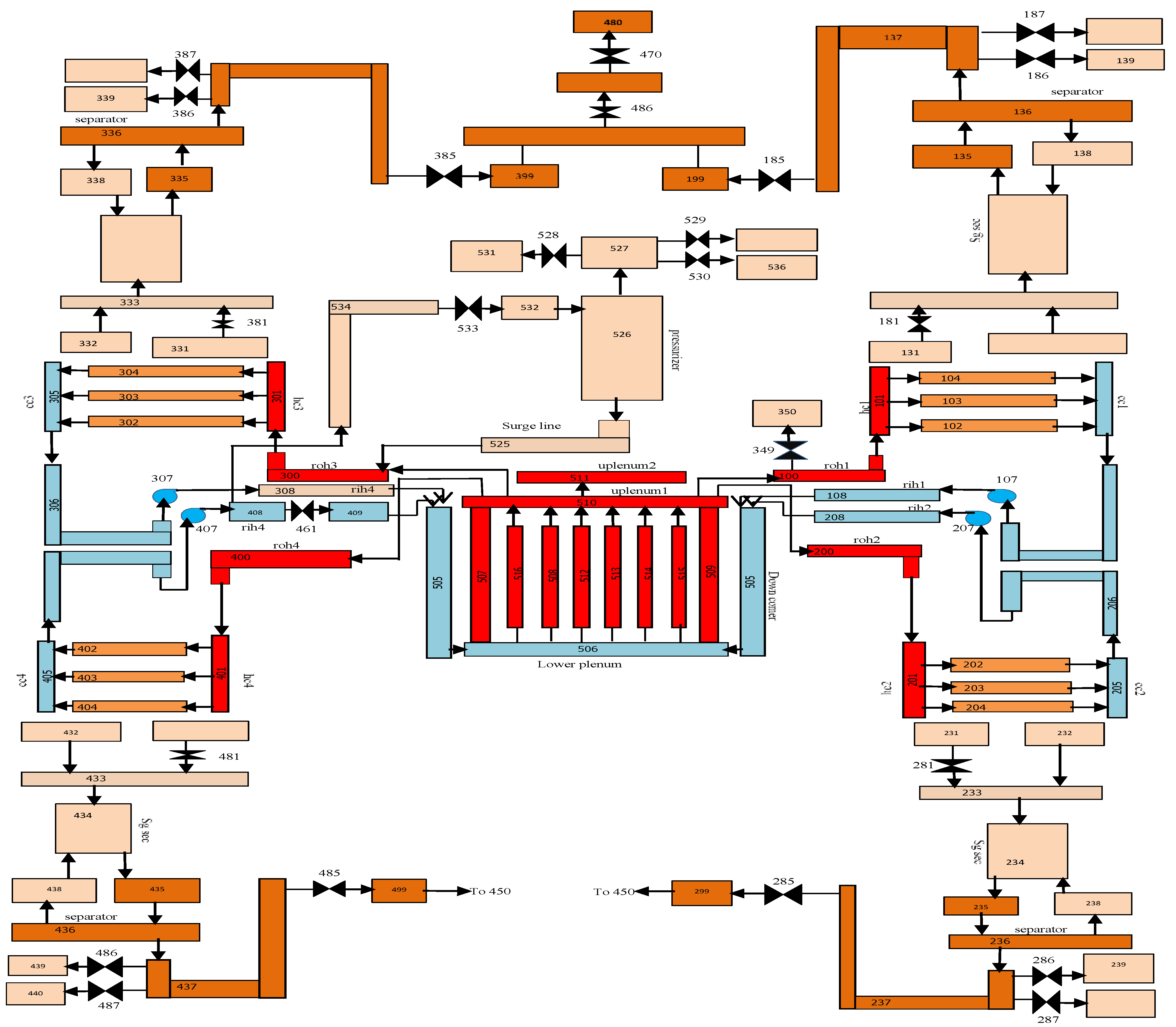
Figure 1. VVER-1000 nodalization.
Jne 02 00035 g001
Figure 2. VVER-1000 nodalization of safety systems.
Jne 02 00035 g002
Figure 3. DELOCA (Guillotine Break) nodding diagram.
Jne 02 00035 g003
Figure 4. Mass flow rate through the leakage.
Jne 02 00035 g004
Figure 5. Flow rate of coolant at the core inlet.
Jne 02 00035 g005
Figure 6. Pressure in the reactor vessel.
Jne 02 00035 g006
Figure 7. Pressure in the pressurizer.
Jne 02 00035 g007
Figure 8. Injection of coolant from ACC.
Jne 02 00035 g008
Figure 9. Injection of coolant from HPIS.
Jne 02 00035 g009
Figure 10. Injection of coolant from LPIS.
Jne 02 00035 g010
Figure 11. Central fuel temperature.
Jne 02 00035 g011
Figure 12. Clad temperature.
Jne 02 00035 g012
Figure 13. Cumulative hydrogen generation.
Jne 02 00035 g013
Table 1. Time sequence of events.
Safety System ActuationTime (s)
Steady state reactor operation≤0
LOCA starts 0
Reactor trip 1.6
Generation of “S” signal 7
Accumulators injection starts8.5
Accumulators emptied170
HPIS injection starts10
LPIS injection starts13
PRZ emptying50
End of the calculation15,100
Publisher’s Note: MDPI stays neutral with regard to jurisdictional claims in published maps and institutional affiliations.