Review

Hydrogen Propulsion Technologies for Aviation: A Review of Fuel Cell and Direct Combustion Systems Towards Decarbonising Medium-Haul Aircraft

by
Daisan Gopalasingam
*,
Bassam Rakhshani
and
Cristina Rodriguez
School of Computing, Engineering and Physical Sciences (CEPS), University of the West of Scotland (UWS), Paisley PA1 2BE, UK
*
Author to whom correspondence should be addressed.
Hydrogen 2025, 6(4), 92; https://doi.org/10.3390/hydrogen6040092
Submission received: 15 July 2025 / Revised: 17 September 2025 / Accepted: 1 October 2025 / Published: 20 October 2025

Abstract

Hydrogen propulsion technologies are emerging as a key enabler for decarbonizing the aviation sector, especially for regional commercial aircraft. The evolution of aircraft propulsion technologies in recent years raises the question of the feasibility of a hydrogen propulsion system for beyond regional aircraft. This paper presents a comprehensive review of hydrogen propulsion technologies, highlighting key advancements in component-level performance metrics. It further explores the technological transitions necessary to enable hydrogen-powered aircraft beyond the regional category. The feasibility assessment is based on key performance parameters, including power density, efficiency, emissions, and integration challenges, aligned with the targets set for 2035 and 2050. The adoption of hydrogen-electric powertrains for the efficient transition from KW to MW powertrains depends on transitions in fuel cell type, thermal management systems (TMS), lightweight electric machines and power electronics, and integrated cryogenic cooling architectures. While hydrogen combustion can leverage existing gas turbine architectures with relatively fewer integration challenges, it presents its technical hurdles, especially related to combustion dynamics, NOx emissions, and contrail formation. Advanced combustor designs, such as micromix, staged, and lean premixed systems, are being explored to mitigate these challenges. Finally, the integration of waste heat recovery technologies in the hydrogen propulsion system is discussed, demonstrating the potential to improve specific fuel consumption by up to 13%.

1. Introduction

Greenhouse gas emissions play a key role in climate change. The UN sustainability goal for climate change aims to keep the temperature increase by 1.5 degrees [1]. CO2 emissions generated by current aircraft technology exceeded 918 million tonnes in 2019, accounting for 2–3% of worldwide emissions [2]. With air travel demand continuing to increase, studies by the International Council on Clean Transportation (ICCT) predict an annual passenger growth rate of 3% until 2050 [3]. Passenger traffic presents challenges for achieving emission reduction targets, emphasising the need for advancements in fuel efficiency, adopting sustainable aviation fuels, and developing low-carbon technologies to ensure the industry’s alignment with global climate goals.
Battery, hydrogen, SAF and hybrid propulsion systems are anticipated to replace traditional propulsion systems. Short-range flight routes offer the greatest potential for transition to electric propulsion, as they typically require minimal modifications to the existing airframe and configuration. Instead of redesigning the entire aircraft, electric systems can often be retrofitted in place of traditional propulsion, making the shift more practical and cost-effective. The energy density of today’s state-of-the-art lithium-ion batteries ranges between 180 and 300 Wh/kg at the pack level. However, a 1330 Wh/kg specific energy battery is needed to achieve a 1000 km+ range for a 150-passenger aircraft [4]. The optimistic projection of the battery specific energy density will reach nearly 1000 Wh/kg by 2050 (Figure 1) [5]. However, a specific energy density of at least 1000 Wh/Kg should be achieved to replace the propulsion of conventional single-aisle aircraft with batteries. This still falls ~25% short of the 1330 Wh/kg required for a 150-passenger, 1000+ single aisle aircraft. Another potential battery technology beyond Li-Ion is the Li-S battery and it is expected to reach an energy density level of 2654 Wh/Kg (theoretical specific energy density). However, this may provide only ~50% cell level efficiency output of the size of 1330 Wh/Kg. Moreover, currently, constraints in battery technology and operational requirements create an unfavorable situation for using batteries in conventional single-aisle aircraft or beyond. Yet, new battery electric aircraft concepts and designs could improve performance [6]. This gap in technology clearly suggests that battery electric propulsion alone is unlikely to be viable for single-aisle aircraft without significantly improving airframe efficiency or hybridization.
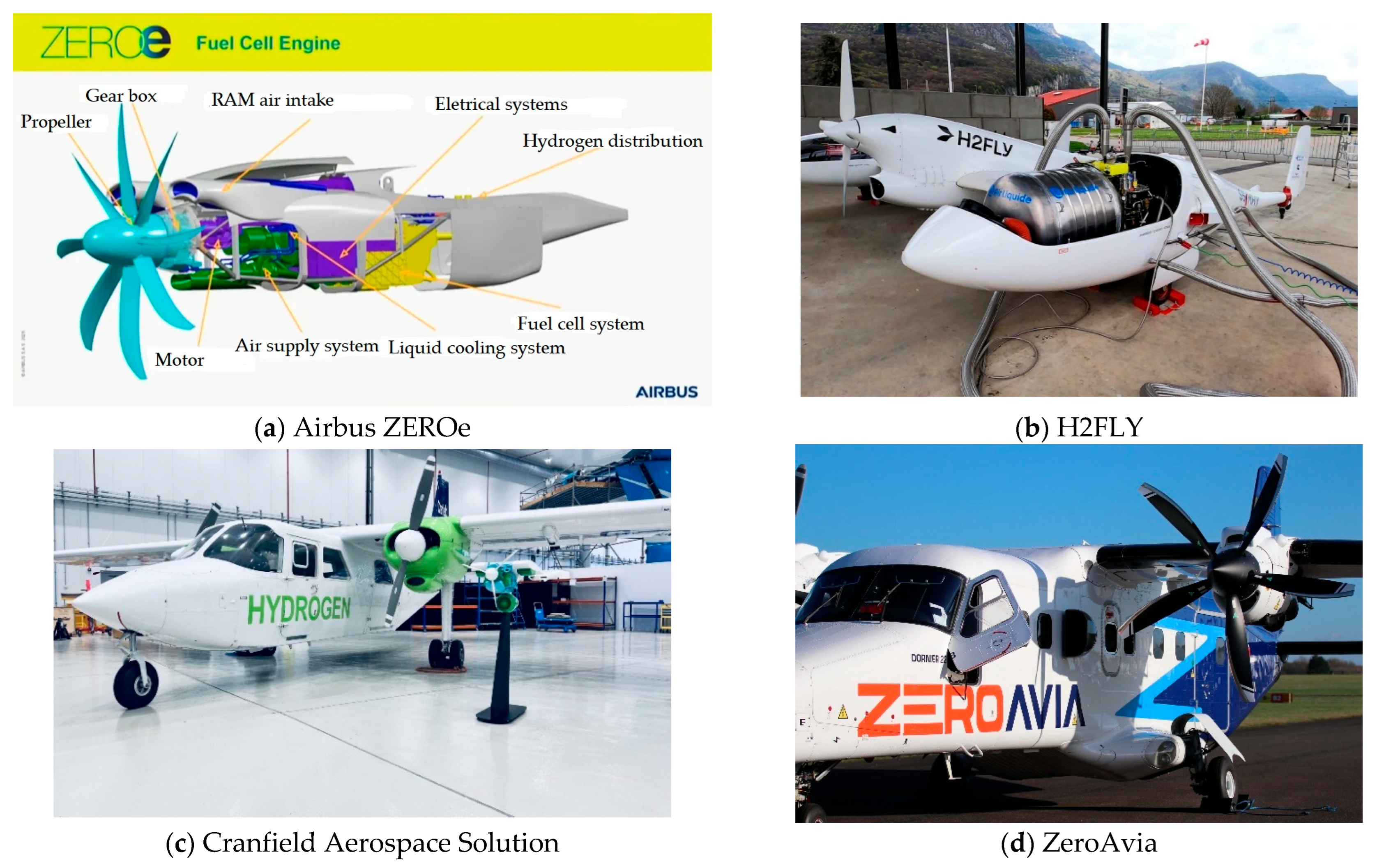
Universal Hydrogen and ZeroAvia have demonstrated the feasibility of using fuel cell powertrains in regional short-range aircraft [7]. Moreover, ZeroAvia is developing a megawatt-class powertrain for 1000 km+ and 90-passenger seat aircraft after successfully testing its 600 kW powertrain for the 400 km+ range and 19-passenger capacity. Figure 2 shows the successfully flown hydrogen electric aircraft using liquid hydrogen. Cranfield Aerospace Solutions and Airbus are developing hydrogen-electric powertrains capable of carrying up to 9 and 100 passengers, respectively.
H2Fly was the first passenger aircraft to successfully fly for several hours and demonstrate the feasibility of a hydrogen-electric powertrain capable of carrying four passengers. A multitude of organizations have invested in hydrogen aircraft. Major studies on hydrogen-powered aircraft such as Cryoplane, Tupolev 155, Lockheed, and FlyZero proved that hydrogen can be a viable solution for transitioning from hydrocarbon-based aircraft. However, significant technological improvements are required in the storage system, propulsion system, and aircraft configuration, as hydrogen does not contain similar properties to those of kerosene fuel [8,9].
Figure 2. Successfully flown powertrains (b,d) [10,11]; under development (a,c) [12,13].
Hydrogen 06 00092 g002
According to the United Nations, it aimed to reduce 45% of emissions by 2030 [14]. IATA introduced a roadmap for aviation to achieve NetZero, and it requires speedy development in fuel cell systems to replace the regional market of aviation [15]. Also, direct combustion to medium-range aircraft should be parallelly improved to achieve the required technology readiness level. Currently, due to insufficient technology maturity, a quick transition from hydrocarbon fuel-based aviation to hydrogen may not be deemed viable [16]. However, recent developments in fuel cell systems with higher efficiencies and liquid hydrogen storage research show the potential and viability of converting existing configurations into hydrogen aircraft.
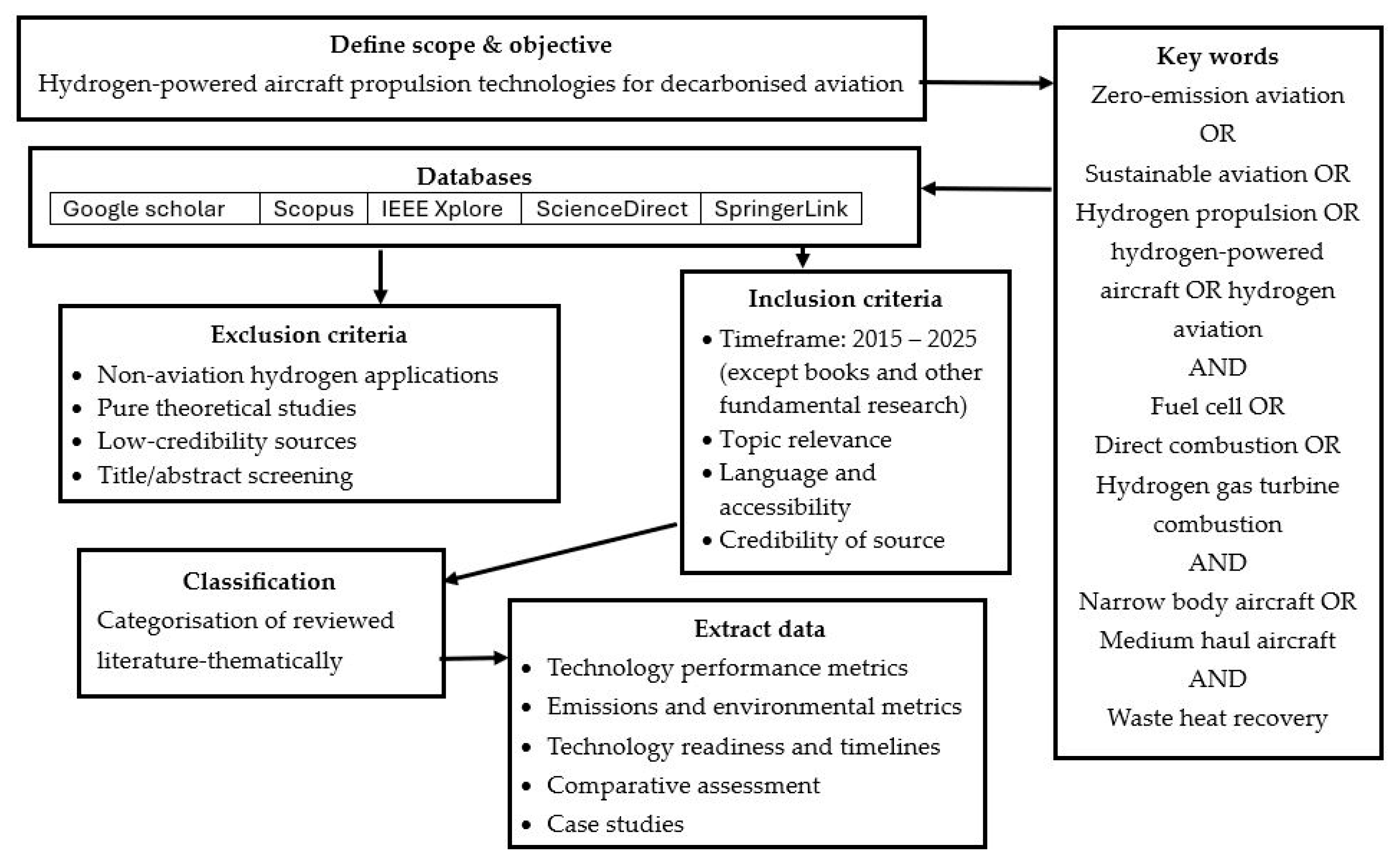
The literature review was conducted based mainly on four databases, and the source selection methodology is shown in Figure 3. This research reviews the current advancements in key technology metrics of the hydrogen-electric powertrains and hydrogen direct combustion engines. In particular, the technical feasibility of medium-range hydrogen-powered aircraft is reviewed in the light of their contribution to the aviation traffic. According to Rakhshani et al. [17], these kinds of aircraft would best satisfy the feasibility and validation criteria for hydrogen retrofit performance. And address the challenges in regulatory and infrastructure requirements.

2. Zero and Low-Emission Fuels Characteristics

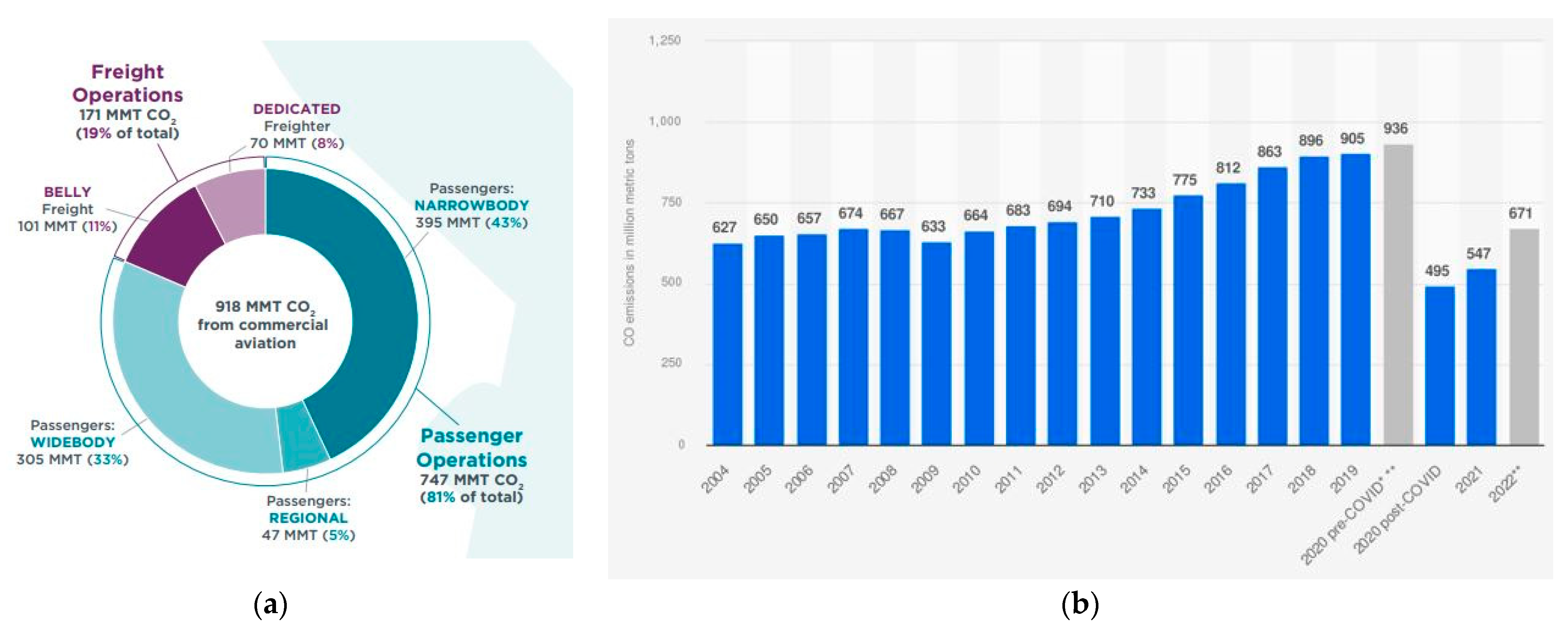
Narrow-body and wide-body aircraft contribute to a larger portion of the total carbon dioxide emission as shown in Figure 4. In 2019, before COVID, the total estimated CO2 emissions were nearly 905 million metric tons. Nearly half of the CO2 emissions come from narrow-body and regional aircraft, i.e., 43% and 5% respectively. The CO2 emission is almost twice as high for regional aircraft per passenger kilometre as medium-haul flights [18]. CO2 emissions are one of the main contributors to global warming, which causes several uncertainties in the world, such as sea level rise, ocean warming, ice mass melting, etc. According to the International Energy Agency (IEA) and IATA, aviation contributes 2.5% of global CO2 emissions. However, it accounted for 3.8% to 4% greenhouse gas emissions.
Alternative propulsion technology offers significant potential to mitigate aviation’s climate impact. A technically and economically viable solution will be needed to decarbonize the aviation sector to achieve NetZero. SAFs seem to be potential fuel for reducing aviation emissions, and they do not require any further modification in aircraft design or systems. However, they do not stop emitting CO2 and other gases into the atmosphere. The life cycle emissions of SAFs may seem to be a viable option for now because it can reduce the emissions from aviation by 65% in 2050 and can reduce the CO2 emission by 80% compared to jet fuel [19]. Currently, SAF is used in aircraft with a 50% kerosene blend but expect to run on 100% by 2030 and by this time, it would replace 30% of Airbus operations [20]. In 2023, Virgin Atlantic flew using 100% SAF from London to New York, proving that flying using 100% SAF (Power-to-liquid) is safe. A recent study by Markl et al. [21], shows that SAF, especially HEFA-SPK, reduce ice number concentrations and non-volatile particulate matter by 56% and 35%. SAF’s price is approximately 2.5 times higher than Jet A fuel, but it is expected to match the price after 2035. Moreover, IATA projections show that 449 billion liters of SAF are required to meet the 2050 target. It is not practical to achieve a true NetZero with SAFs. The AIA report by Cambridge University shows that SAFs are not the only solution to reduce emissions [22]. Battery-powered propulsion is currently not feasible for narrow-body aircraft due to the batteries’ significantly lower energy density than conventional aviation fuels. Jet fuel has an energy density of approximately 43 MJ/kg, whereas advanced lithium-ion batteries offer only about 1 MJ/kg [23]. This vast disparity means that the weight and volume of batteries required to power a narrow-body aircraft would be impractically considerable, severely limiting the payload capacity and range. Additionally, the weight of batteries remains constant during flight, unlike fuel, which is consumed, leading to further inefficiencies [24]. With sufficient technological advancements, alternative propulsion methods could replace jet fuel-powered aircraft. Also, AIA recommends improving the technologies to achieve a true zero flight, including further research and development on hydrogen-powered aircraft [22].
The key properties of hydrogen, such as zero carbon emission, high energy density, high ignition temperature, broad flammability range, and fast flame speed, make it a potential fuel for aviation. It only produces water as an emission. Moreover, the energy density of hydrogen is approximately three times higher than that of the current Jet A fuel. Recent research shows that fuel cell and direct hydrogen combustion engines can reduce the fuel mass by 50% and 80%, respectively, compared to Jet A [17]. However, the hydrogen volumetric density is four times less than kerosene, which requires more space to store hydrogen in the aircraft. The high specific heat of hydrogen increases the turbine inlet temperature and operating pressure ratio, which leads to a reduction in SFC [8]. Moreover, the lower density of hydrogen leads to a lower lift-to-drag ratio, lowering the wing loading at take-off. The major problem with hydrogen combustion is contrail formation and NOx emission. Contrails contributed to 70% of the change in temperature due to aviation in 2019 [25]. However, the temperature changes due to contrails and NOx emissions of hydrogen-powered aircraft are 50% and three times lower than those of kerosene-powered aircraft [26]. Also, this paper [26] evaluated and compared the environmental impact of hydrogen combustion due to emissions such as Nox, H2O, and contrails with kerosene combustion. Another paper [27] reviewed the climate impact of hydrogen combustion, and further research on contrails is required, as there are still some uncertainties in correctly calculating the impact on the environment [28]. Table 1 shows the critical parameters required to determine the feasibility of the alternative propulsion systems.
Table 1. Technological parameters of alternative propulsion systems.
ParameterFuel CellsHydrogen
Combustion
SAFBattery HybridReferences
Specific Energy33–40 MJ/kg33–40 MJ/kg~43 MJ/kg0.2–0.4 MJ/kg[29,30]
Energy Efficiency45–60%35–45%38–42%80–95%[31]
System ComplexityVery High: Stack, humidifier, compressor, cooling, and inverterModerate: Turbine and modified combustorLow: Drop-in fuel in existing enginesHigh: Battery packs, inverters, electric motors, and BMS[32]
Fuel/Storage CostEUR 6–10/kg LH2EUR 6–10/kg LH2EUR 1.5–3/kgEUR 100–200/kWh[33]
GHG EmissionsZeroWater and NOx ~80% reductionZero [32,33,34]
TRLMediumMediumHighHigh[32,33]
ConstraintsCooling, durability, and densityFlame stability, NOx controlSupply, feedstock, and LCAWeight, cooling, and battery aging[32]
Two potential fuels to replace fossil fuels in narrow-body and wide-body aircraft are hydrogen and SAFs. SAFs are not the solution for NetZero due to their life cycle emissions. However, they are likely to continue being used until alternative propulsion systems are developed for wide-body and narrow-body aircraft. Hydrogen can be utilized in two primary ways: to produce electricity through fuel cells or directly combusted in gas turbine engines. Hydrogen combustion produces 2.6 times more water vapor than kerosene fuel [35]. On the other hand, the overall efficiency of the hydrogen fuel cell system could be achieved by 40–60%, compared to about 30–40% for kerosene gas turbine engines. This implies that aircraft powered by fuel cells could consume less fuel for the same energy output [36]. The AIA model shows that hydrogen-electric aircraft will increase their range up to 4000 km by 2035, and this will replace the fleets of narrow-body aircraft such as the A320 and B737 with hydrogen-electric propulsion [22]. Additionally, the cost of green hydrogen production is expected to decrease after 2040, becoming more economical than crude oil, natural gas, and PtL SAFs [2,37]. Table 2 shows the potential hydrogen production pathways and their economic and environmental impact.
Table 2. Key parameters for gray, Blue, and Green Hydrogen Production Pathways.
MetricGray
Hydrogen
Blue
Hydrogen
Green
Hydrogen
References
CO2e Intensity (kg CO2e/kg H2)~9–11~1.5–5~0.05–1.5[38,39]
TRL989[40]
Cost (USD/kg)USD 1.00–USD 2.50USD 1.50–USD 3.50USD 2.50–USD 7.50
FeedstockNatural gasNatural gas + CCSRenewable electricity + water[41,42]
Water consumption (kg H2O/kg H2)~4–7~6–9~9–12[43]

3. Hydrogen-Powered Aircraft

3.1. Fuel Cell Propulsion

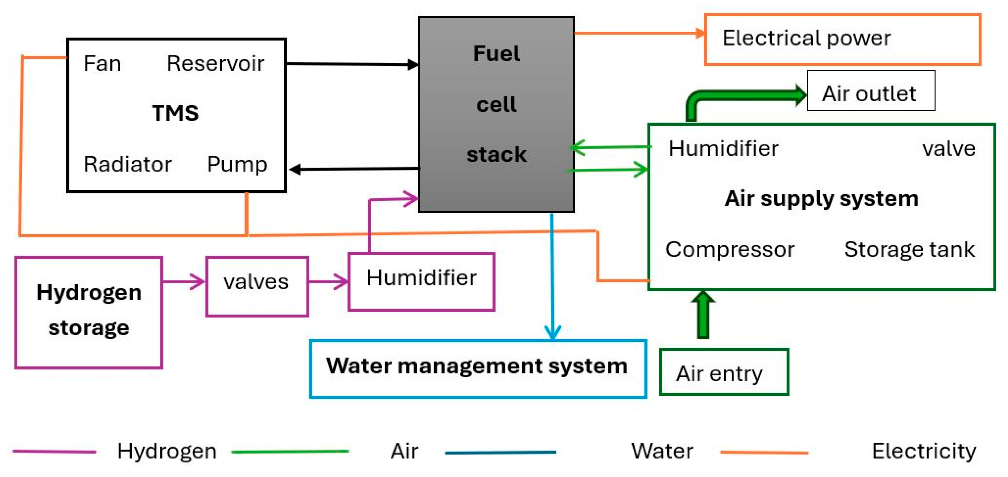
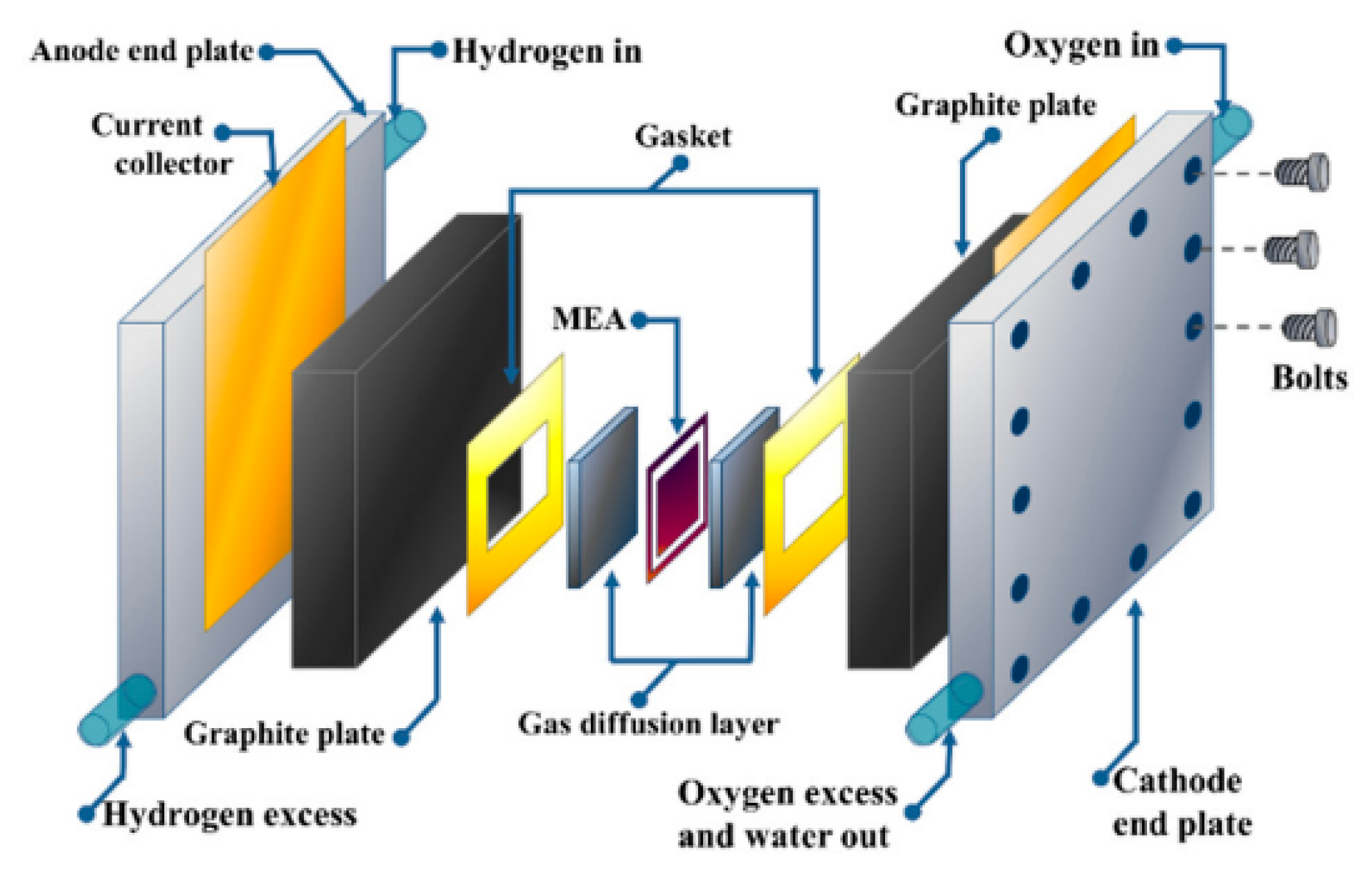
Fuel cells convert fuel and air into electricity, producing only water as a by-product. Fuel cell technology, types, and systems are well characterized in many studies [44,45,46]. The application of fuel cells in aircraft propulsion is reported in the literature accordingly [47]. A fuel cell-based propulsion system is already integrated into road vehicles using compressed hydrogen gas as fuel [48]. However, adopting fuel cell powertrains in aircraft is challenging due to their lower specific power, specific volume, and efficiency. As shown in Figure 5, the fuel cell system consists of several systems and components. A fuel cell stack consists of several cells and it requires other subsystems to operate in an optimum condition.
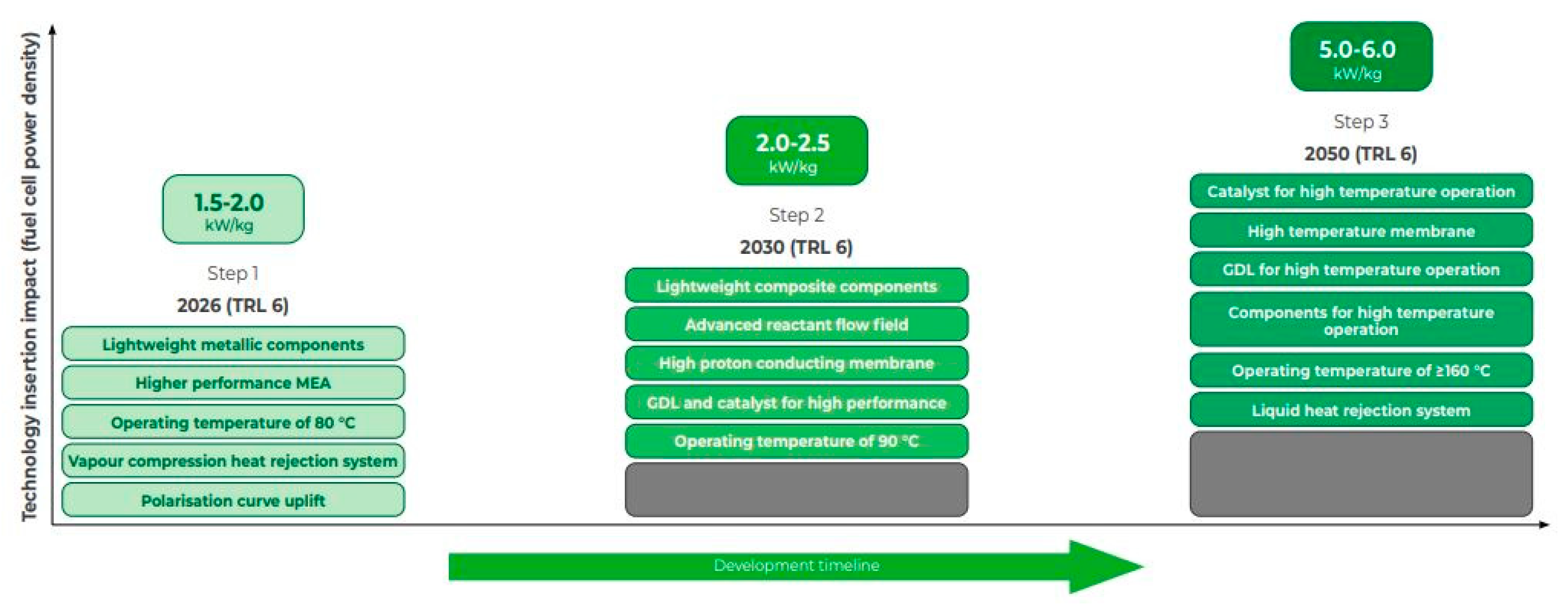
The ATI provides the roadmap for fuel cells (Figure 6) with the technology requirements and projections on key performance metrics [49]. It shows that a shift in fuel cell type should be made, which could help achieve a power density of up to 6 kW/kg, similar to that of the conventional propulsion system.

3.1.1. Fuel Cell Types

There are two potential types of fuel cells for aviation applications: (a) the polymer electrolyte membrane fuel cell (PEMFC) and (b) the solid oxide fuel cell (SOFC). PEMFC has been classified into two types based on their operating temperature, LT-PEMFC and HT-PEMFC. LT-PEMFC has been used by major hydrogen powertrain developers (Table 1). This type of fuel cell has already achieved a significant milestone in retrofitting megawatt-class power-consuming aircraft (Dash 8-300). SOFCs and HT-PEMFCs can perform with a higher electrical efficiency compared to LT-PEMFC, but due to their low TRL, it is not yet suitable for now [51]. LT-PEMFC (Figure 7) polymer electrolyte membrane fuel cell systems become more complex and challenging as the output power increases [52]. One primary challenge is adequate heat and water management; higher power levels lead to increased heat generation and water production, which can cause membrane dehydration or electrode flooding, adversely affecting the performance and durability [53]. Additionally, at elevated power outputs, mass transport limitations become significant due to insufficient reactant supply and the accumulation of water in the catalyst layers, leading to voltage losses and decreased efficiency [54]. Platinum-based catalysts are poisoned by impurities like carbon monoxide, which reduces the effectiveness of the fuel cells [55]. Maintaining uniform temperature and reactant distribution across larger fuel cell stacks also becomes more challenging at higher power levels, negatively impacting the performance and durability [45]. Table 3 shows the successfully developed hydrogen electric powertrains using PEMFC.
Table 3. Various powertrains developed and tested successfully.
IndustryFuel Cell TypeAircraft TypeCapacity of the AircraftPowertrain CapacityReferences
HY4LT-PEMFCExperimental aircraft4-seater80 kW[56]
ZeroAviaLT-PEMFCPiper Malibu M3506-seat aircraft250 kW[57]
ZeroAviaLT-PEMFCDornier 22819-seater600 kW[58]
Universal HydrogenLT-PEMFCDash 8-30056-seater1–2 MW[59]
On the other hand, HT-PEMFCs operate at 200 degrees and higher, leading to enhanced electrode kinetics, improved tolerance for fuel impurities like carbon monoxide, and simplified water management since water remains in the vapor phase, reducing flooding issues [60].
Recent advancements in high-temperature proton exchange membrane fuel cells (HT-PEMFCs) indicate promising potential for scaling hydrogen-electric propulsion systems to larger aircraft. In 2023, ZeroAvia developed an HT-PEMFC stack with a specific power of 2.5 kW/kg at cell level for a 20 kW module. It is expected to achieve the power of over 3 kW/kg at the system level in 2025 to support their ZA2000 powertrain, designed for a 40–80-seater aircraft. Feasibility studies of FlyZero show that single-aisle hydrogen-electric aircraft could become viable between 2035 and 2050. Their projections estimate that HT-PEMFCs, excluding balance of plant (BoP) components/cell levels, could reach a specific power density of approximately 16 kW/kg while maintaining a comparable system mass to LT-PEMFCs by 2035. The fuel cell system-level efficiency achieved for aviation applications is presented in Table 4. FlyZero further estimates that LT-PEMFCs, including the BoP/system level, could achieve 3–3.5 kW/kg and 75% efficiency by 2050, with additional improvements of up to 5–6 kW/kg possible through the adoption of high-temperature fuel cells and superconducting powertrains [49]. Comparatively, NASA has projected a specific power of 1.7 kW/kg for LT-PEMFCs by 2025. ZeroAvia’s 600 kW fuel cell powertrain, developed in the same timeframe, has reached a specific power of 1 kW/kg, closely aligning with NASA’s forecast. Additionally, HyPoint has projected a specific power of 3 kW/kg for HT-PEMFCs by 2025, a target that FlyZero estimates for 2035 [61]. ZeroAvia also anticipates that HT-PEMFC systems with a specific power of 4 kW/kg will be capable of powering 100+ seat single-aisle aircraft by the early 2030s, supporting the transition toward zero-emission, medium-range aviation [58]. Studies on wide-body Boeing 787-8 aircraft show that advancements in the well-to-wing energy efficiency and the power density of fuel cells can enable liquid hydrogen (LH2) fuel cell aircraft to carry 200 passengers over 6000 km and a 20% higher range than gas turbine aircraft [62].
Table 4 shows the efficiency, operation pressure, temperature, and power densities of potential fuel cell types in aviation. The SOFC seems unlikely to be feasible soon due to its specific power and complex thermal management, though it has a higher operating efficiency. NASA’s Glenn research center has developed an advanced solid oxide fuel cell (SOFC) that could achieve a specific power density five times higher than current SOFCs, i.e., up to 2.5 kW/kg. This highly efficient fuel cell can operate on a diverse range of fuels, including hydrogen and hydrocarbon-based options such as methane, diesel, and jet fuel, without the need for external reformers [63].
Table 4. Fuel cell for aircraft propulsion.
TypeOperating Pressure (Bar)Operating
Temperature
(Celsius)
Power Density (kW/kg)
(Cell Level)
System-Level EfficiencyReferences
LT-PEMFCUp to 360–80Up to 7<60%[50]
SOFC1–10600–10000.51 <65%[64]
HT-PEMFCUp to 3120–2002.5 <60%[58]
Several hydrogen-electric powertrains have been successfully developed and tested for commercial passenger aircraft of varying configurations and capacities (Table 3). These developments primarily focus on regional or short-range commuter aircraft, demonstrating significant progress in applying hydrogen fuel cell technology to regional aviation. Currently, no fuel cell powertrain has achieved the capacity to be installed beyond regional aircraft categories. However, using a sophisticated catalyst design and lightweight, oxygen-enriched air and better-performing materials in fuel cell stack components, it is possible to improve the power density by a factor of at least five, which helps to reduce the weight of the future aircraft [65].

3.1.2. Balance of Plant (BoP)

The BoP in a fuel cell system consists of auxiliary components and subsystems necessary to support the fuel cell stack operation. It manages the fuel supply, air delivery, thermal regulation, water management, and power conditioning to ensure the optimal performance and durability of the fuel cell system. Figure 8 shows the balance of plant modules and their interaction with other modules to support and improve the performance of the fuel cell system [66,67]. The BoP components such as humidifiers, compressors, and heat exchangers are required for high-power operations, resulting in higher parasitic power consumption, reducing the overall net power output of the fuel cell system [68]. Nearly half of the energy is converted into heat during electricity generation in the fuel cell. It must be removed from the stack to maintain optimal performance. High-efficiency fuel cells require less hydrogen for the same power output, reducing the overall fuel storage needs and minimizing the system weight and complexity. However, higher power output and efficient fuel cells may operate at lower temperatures (low-grade waste heat), impacting the thermal management approach. In such cases, systems with advanced heat exchangers or phase-change materials might be needed to regulate the temperature while keeping the weight low [69]. Microchannel heat exchangers have a high surface area-to-volume ratio that can effectively manage the high thermal loads generated by fuel cells and inverters without adding significant weight. It can reduce the system weight by up to 30% and reach the specific power of 0.65 kW/kg compared to other traditional cooling techniques [70].
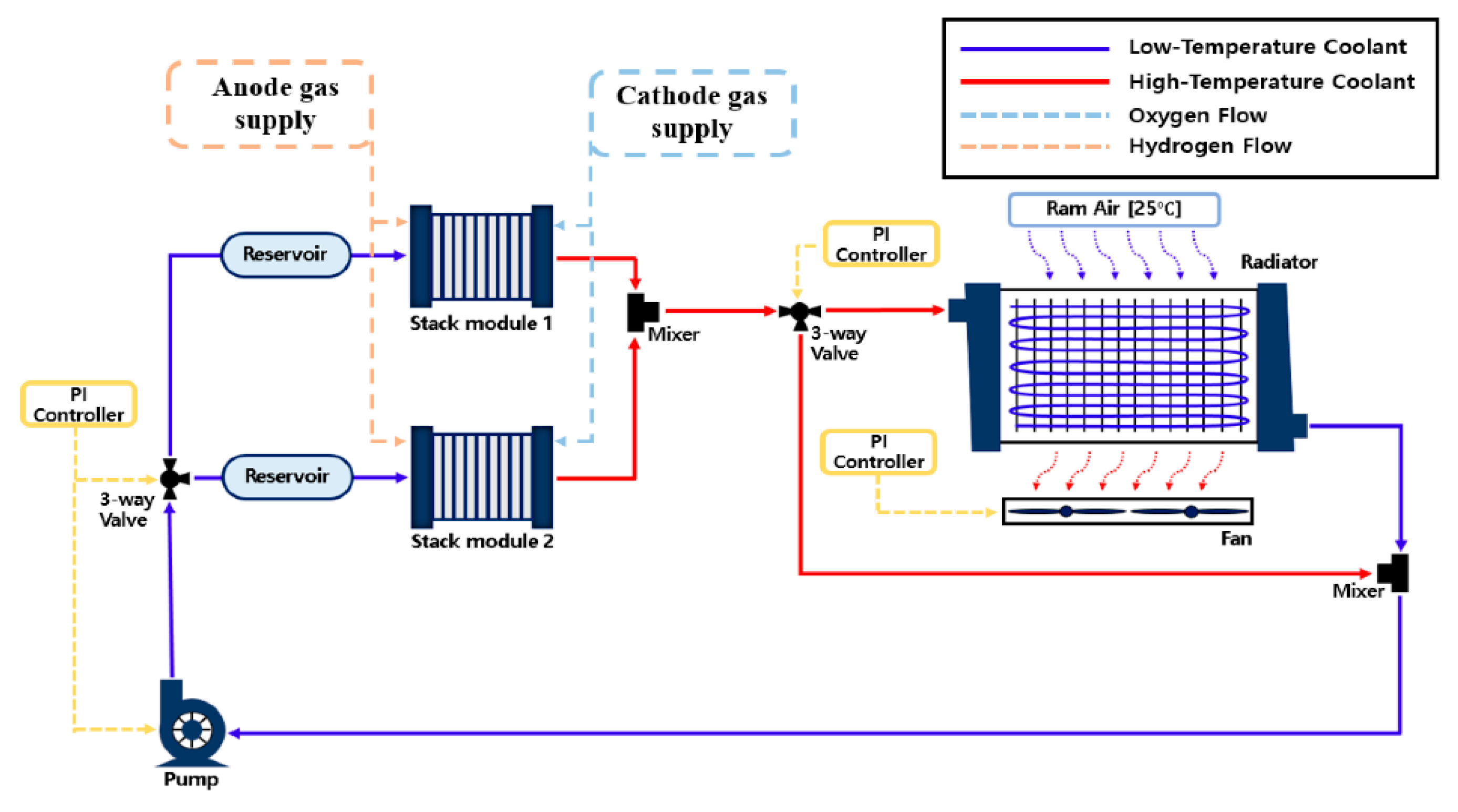
A phase-change cooling system is capable of handling larger heat power, and it reduces the weight and complexity of the thermal management system. Phase-change materials (PCMs) can store excess heat temporarily and release it slowly, stabilizing temperatures and reducing the cooling system’s peak load. A study by Striednig et al. [70] shows that the phase-change heat pumps reduce engine and aerodynamic drag by 23% and 98.7% (94% less weight) compared to liquid cooling (LC) for MW-class LT-PEMFCs. A recent study on MW-class LT-PEMFC cooling systems shows that the mass of the two-phase cooling system (TPC) with an accumulator is 35% lower than the LC, and without an accumulator, the TPC weighs 2.4 times less than the LC [71]. Nanofluids can be applied in cooling systems as they have a higher thermal conductivity, which improves efficiency and reduces the size of the TMS, but it may increase the pumping power [72]. A study by Islam et al. [73] shows that the frontal area of the heat exchanger reduced by 21% compared to the baseline fluid for the same coolant flow rate at a 0.05% volume of nanoparticles, and the pumping power increased by around 1%. Another analytical study by Fly et al. [74] shows that the frontal area can even be reduced by 27% by changing from liquid to evaporative cooling for LT-PEMFC. On the other hand, HT-PEMFC minimizes the mass of the TMS by 65% compared to the LT-PEMFC system [75]. Figure 9 illustrates a typical schematic configuration of a cooling system for fuel cells that can be utilized in the BoP. Multitudes of similar configuration are reported in literatures such as [76,77,78].
In aviation, where ambient pressure and humidity vary significantly (due to ISA conditions), maintaining the optimal hydration of the fuel cell membrane without flooding becomes complex. Multiple strategies have been proposed to address this. Water management methods and techniques and materials such as changing the shape of the flow passage, material, and an efficient control system are improving the fuel cell efficiency, lifespan, and performance [79,80]. Nano-engineered GDLs improve water management and allow for effective excess water removal, leading to thinner and lighter electrodes and reduced weight in fuel cell systems, improving the power density by 14% with a gradient pore structure compared to a conventional structure [81]. Advanced polymer electrolyte membranes that incorporate hydrophilic additives and nanomaterials enhance water retention and enable thinner membranes, thereby reducing the overall weight of the membrane assembly [82]. Graphene-based coatings on membranes and electrodes have improved water transport and reduced membrane dehydration, further boosting fuel cell efficiency [83]. Furthermore, ML algorithms could improve the water flooding issue by monitoring and controlling the fuel cell system’s input and output parameters. Further quantitative studies are required on specific density variations and the mass of fuel cell systems by incorporating technologies and innovative approaches.
LT-PEMFCs face water management challenges because their operating temperature is below the boiling point of water, leading to potential water flooding issues. In contrast, HT-PEMFCs operate at significantly higher temperatures and do not experience serious water flooding issues. And it has a simple BoP design, higher impurity tolerance, and higher-grade waste heat [84]. A detailed review of the issues and gaps is identified on TMS in HT-PEMFC, and addressing these gaps provides a suitable performance for aerospace applications [85]. Future studies could enhance the system-level efficiency by focusing on the overall thermal system behavior and minimizing parasitic power losses through the integration of waste heat recovery systems [86].

3.1.3. Power Electronics Systems

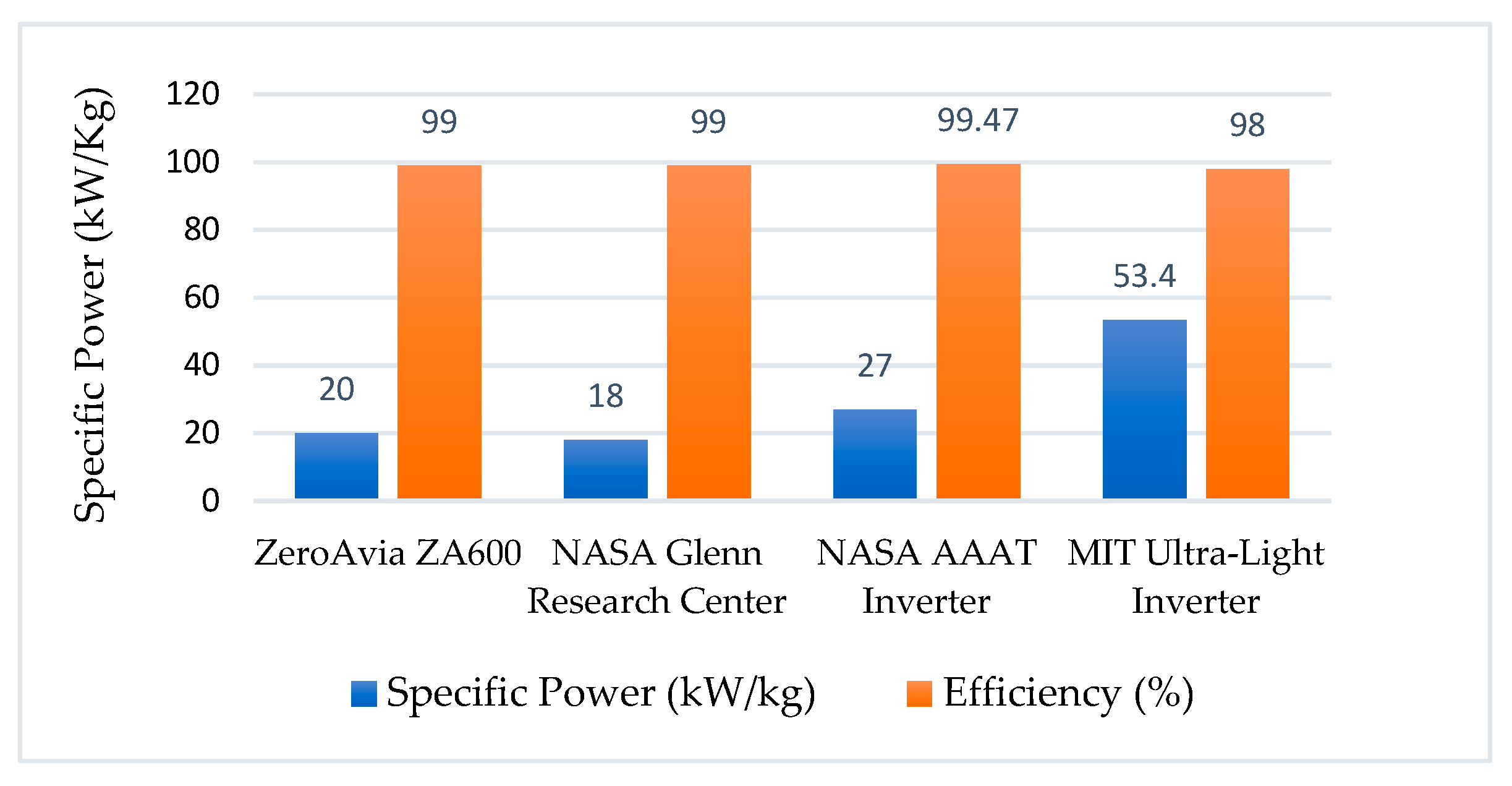
Power management and distribution (PMAD) systems in hydrogen-electric aircraft propulsion encompass components such as inverters, cables, converters, buses, and switches. Traditional power transmission methods relying on metals and alloys contribute significantly to the overall weight of the PMAD. Recent advancements have focused on reducing weight and enhancing the efficiency of inverters used in megawatt-class powertrains. ZeroAvia inverters can produce a maximum of 450 kW power at 800 VDC, with a 20 kW/kg power density for the ZA600 powertrain and a maximum efficiency of 99% without using cryogenic cooling methods. The study conducted by Wang et al. [80] reviews the key projects and technologies that improved the specific power and efficiency of the inverter for mega-watt class powertrains used for aircraft propulsion applications, and this concludes that the inverters for mega-watt class powertrains are approaching 20 kW/kg and 99% of specific power and efficiency. NASA’s AATT project investigated several capacity inverters and other electrical components such as motors for turbo-electric and parallel hybrid electric powertrains suitable for tube wing narrow-body and hybrid wing-body aircraft. The NASA Glenn Research Center explored a cryogenically cooled inverter system for the MW-class propulsion, achieving a specific power of 18 kW/kg and 99% efficiency [87].
An experimental 1-MW inverter developed under NASA’s Advanced Air Transport Technology project achieved a specific power of 27 kW/kg and an efficiency of 99.47% at 500 kW. This inverter utilized advanced cooling systems, where liquid nitrogen cooled EMI filters and gaseous nitrogen regulated the junction temperature of SiC MOSFETs to maintain performance.
Additionally, researchers at MIT have designed an ultra-light inverter capable of producing 53.4 kW/kg specific power with over 98% efficiency for a 1-MW motor [88]. This inverter comprises ten 100 kW three-phase inverter modules, demonstrating the scalability of modular designs for electrified propulsion. Also, 1-MW integrated modular motor drive is developed at the NASA test facility (NEAT), with a specific power of 9 kW/kg [89]. The specific power density and efficiency of the potential inverters are shown in Figure 10.
Incorporating hyperconducting materials in the power transmission weighs up to 3–4 times less compared to conventional high voltage power distribution systems [90]. Hydrogen-electric PMAD systems rapidly advanced toward high efficiency (99%+) and high-power density (20–50 kW/kg). This research [91] shows a 60% mass reduction in aircraft power electronics due to smaller conductor cross sections. And the benefits of cryogenics in power electronic devices for aircraft propulsion are reviewed, also identified the components suitable for low temperatures [92]. Airbus is investigating cryogenics and superconducting technologies under the ASCEND program. The current limitation on the power density in power electronics could be overcome through weight reduction in the cable [93]. Cryogenic cooling and superconducting materials are key to reducing weight and improving performance.

3.1.4. Electric Motor

Researchers at the University of Illinois developed a 1 MW, 10 kW/kg, and 98% efficiency motor using the cryogenically cooled superconducting permanent magnet motor. The NASA Glenn Research Center is developing a 1.4 MW, 16 kW/kg, and 98% wound-field synchronous motor with a superconducting rotor. Ohio State University is investigating 2.7 MW, 13 kW/kg, and more than 96% induction motors using innovative variable cross section wet coil cooling on the stator. Moreover, it has completed a conceptual design of a 10 MW ring motor with approximately 1 m in diameter and 5000 RPM [94]. As part of the H2FlyGHT program, the University of Manchester is conducting advanced research on hyperconducting motor coil design for a cryogenically cooled electric motor, intended to power a 2 MW hydrogen-electric propulsion system [95]. A joint venture between Airbus UpNext and Toshiba aims to develop a superconducting motor for an MW-class powertrain [96]. ZeroAvia estimates that, for narrow-body aircraft such as the Airbus A320 or Boeing 737, electric motors must achieve a specific power density exceeding 15 kW/kg, as these aircraft consume over 12 MW of power at cruising, even with airframe improvements. Currently, ZeroAvia has developed a 660 kW electric motor operating at 2500 rpm, reaching a specific power density of 5 kW/kg [58].
FlyZero’s target for 2030 for the electric motor is 23 kW/kg and 25 kW/kg in 2050, enabling narrow-body aircraft (like A320 and 737) to be capable of flying with 100+ seat aircraft [49]. Figure 11 illustrates the projected specific power trends for electric motors from various studies. Furthermore, advancements in superconducting motors could boost power densities up to 20 kW/kg by 2035, significantly surpassing the current technology benchmark of approximately 5 kW/kg.

3.2. Hydrogen-Electric Powertrain

Based on the developments in powertrain components such as the converter, inverter, motor drive, and motor, it is possible to achieve a 70% efficiency without considering the fuel cell efficiency (Figure 12). A fuel cell consists of several components; its efficiency strongly depends on the BoP efficiency. So far, the fuel cell system has achieved nearly 50% efficiency at the system level.
The powertrain’s overall efficiency is around ~35% if the fuel cell is included. Power electronic components and motors have significantly improved the efficiency and specific power. FlyZero’s projections indicate a 75% fuel cell efficiency by 2050, resulting in a ~52% powertrain efficiency.
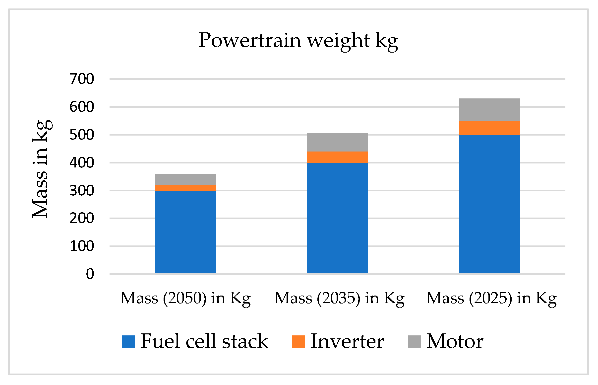
For a 1 MW powertrain, the weight can be estimated using the specific power values of the components in the hydrogen-electric powertrain across different timeframes. The component specific power values are shown in Table 5 for different timeframes.
Hydrogen storage is not included in this calculation as it strongly depends on the technology and performance parameters of the aircraft. Moreover, the powertrain weight is expected to be nearly half in 2050, like FlyZero’s projection [50]. It is worth noting that the improvement in fuel cell systems strongly influences the weight of the powertrain. The total take-off mass of 9 to 20-seat aircraft increases by 10% to 13% for hydrogen-powered fuel cell aircraft [101]. Another study shows that converting Cessna 208 aircraft into fuel cell-powered increases its total-off weight by ~15% [102]. Both these studies are based on projected component performances for 2035. Figure 13 shows how the mass of the powertrain varies based on different timeframes.
Further improvements in the efficiency and specific power of the hydrogen-electric powertrain, which are considered as key parameters in assessing the scalability of a propulsion system, could be improved by adopting cryogenics and lightweight materials. According to the FlyZero study, there were no noticeable improvements in the efficiency or power density as the powertrain scaled from half a megawatt to 4 megawatts. However, this study [103] shows that the power density of the powertrain including the storage system could be achieved up to 1.5 kW/kg in 2035 with the integration of cryogenic cooling and superconducting technology. Additionally, TMS is identified as a significant sector for improvement as it accounts for 21% of the total weight of the hydrogen-electric propulsion system. However, as the future fuel cell system is HT-PEMFC, it significantly reduces the weight of the thermal management system.

4. Hydrogen Direct Combustion

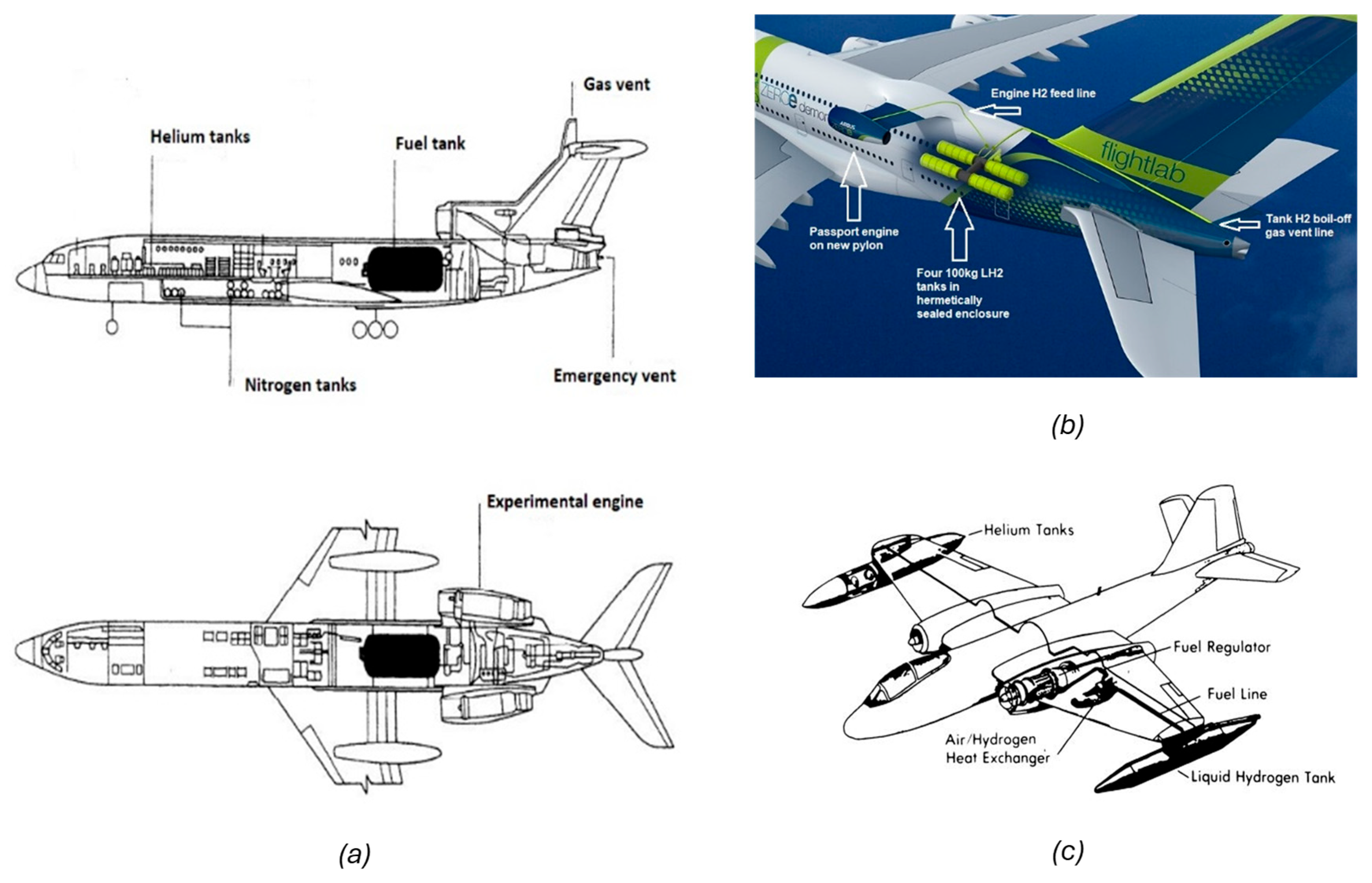
Hydrogen’s high energy density by weight is another advantage for aviation applications, offering the potential for long-range flights with significantly lower carbon footprints than traditional jet fuel. A liquid hydrogen aircraft with a Pratt Whitney turbojet engine by Lockheed in 1956 was built and tested [8]. Another notable project in the 1980s was Russia’s Tupolev Tu-155, the first aircraft to fly partially powered by hydrogen combustion (Figure 14). This was a modified trijet Tu-154 airliner that successfully used cryogenically stored liquid hydrogen as fuel for one of its three engines, achieving multiple test flights. Even though hydrogen combustion engines are not yet commercialized, major conventional aircraft engine manufacturers such as GE, Safran, Roll Royce, and P&W are working on their roadmap to bring future hydrogen-powered turbine engines into the regional, medium, and long-range aviation market. GKN Aerospace aims to bring hydrogen gas turbines for single-aisle aircraft by 2035 with its multiple partners [104]. In addition, Airbus is working on three different projects including hydrogen combustion-based aircraft, and aims to the market by 2035; moreover, it successfully tested its ZEROe engine for about 4 h in Toulouse [105]. Rolls-Royce is developing its hydrogen turbofan engine to power narrow-body airlines by the middle of 2030, and it has tested using 100% hydrogen in the Pearl 700 engine in 2023 at DLR, Germany. BeautHyFuel conducted a successful test in January 2024 on the TP-R90 engine with gaseous hydrogen fuel [106]. And in January 2025, the first liquid hydrogen-fed gas turbine was successfully tested for light aircraft.
Feasibility studies on hydrogen-powered aircraft such as Lockheed, Cryoplane, and Flyzero show that hydrogen can be an alternative fuel for aircraft propulsion, including narrow-body aircraft with advancements in propulsion systems, storage, and aircraft configurations [9,49,107]. While the water produced by hydrogen combustion absorbs some of the heat and thus reduces NOx formation, water vapor itself can contribute to climate effects. In addition to this, the overall global warming impact of hydrogen is lower than that of jet fuel [108].

4.1. Combustion Techniques

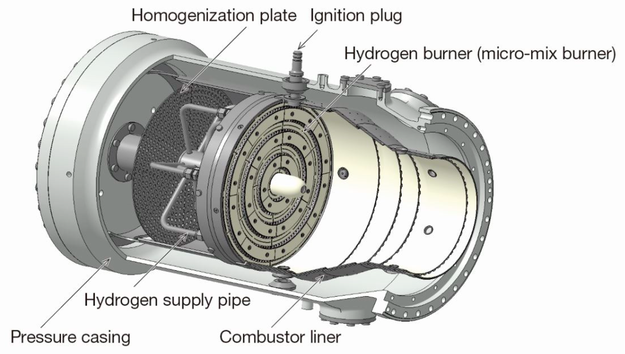
Hydrogen combustion engines for aviation require significant modifications to the combustion chamber due to hydrogen’s high diffusivity and broad flammability range (4–75% by volume in air). Uneven fuel–air mixing, flame instability, and flashback are significant problems in hydrogen combustors, and hydrogen combustion produces a larger valve of temperature than kerosene at its stoichiometric ratio. Still, it can be burned at lean mixing ratios. As the Nox formation rate rises exponentially with the flame temperature, lowering the flame temperature is a crucial goal. Advanced injector designs (e.g., swirl, jet in cross-flow, and multi-point), premixing burners, and staged combustion mitigate these challenges by ensuring more uniform mixtures and stable operation. The primary purpose of the combustor design is to reduce or eliminate NOx emissions and overcome technical challenges associated with the development of a compatible combustor (Figure 15).
Several advanced combustion technologies are being explored to mitigate NOx emissions in hydrogen-fueled engines. This research [110] reviews the low emission combustion technologies for kerosene gas turbine engines at high and low TRL levels. Hydrogen’s flammability range is higher than kerosene, so it can be burned leaner than kerosene. One approach is lean-burn combustion, which involves a high air-to-fuel ratio to lower combustion temperatures, thus reducing NOx formation. Another technique is flameless or mild combustion, where fuel and air are premixed and combusted at lower temperatures, eliminating hot spots that produce lower NOx up to less than 90% of the baseline Jet A combustor [111]. Recent research on flameless hydrogen combustion based on lean azimuthal flame technology reduces NOx up to a single digit in hydrogen combustion engines [112]. Water injections and humidified air combustion are also being investigated as methods to lower NOx emissions in hydrogen combustion engines. Water injections directly cool the combustion chamber, reducing peak temperatures and offering a 50% NOx reduction for kerosene-powered combustion engines [113]. Steam injection and recovering water vapor from the engine could reduce NOx emissions by 80% in LH2 combustion gas turbine engines [114]. A recent numerical investigation on water injections in turbofan engines shows that a 40–50 K temperature drop across high-pressure compressors leads to a significant reduction in Nox [115].
Even though the premixing of air and hydrogen produces a higher performance and reduces NOx emissions, there is a flashback issue. On the A320 Auxiliary Power Unit (APU) GTCP 36-300, the use of the micromix diffusive combustion system resulted in a NOx reduction of approximately 60–80% compared to the original kerosene-based combustion system [116]. A numerical study shows that the micromix combustor has the potential to reduce the NOx emission by 80% and the possibility to scale up for real gas turbine applications [117]. Furthermore, an independent author suggests that micromix and staged combustion could be used in future hydrogen engines as it has lowered the NOx emission and improved the combustion efficiency [118]. This research [119] summarizes the numerical studies on micromix combustors for aircraft applications focused on reducing NOx emissions. A micromix burner is shown in Figure 15. In addition to the above-discussed combustors, there are other potential combustors at a higher TRL such as RQL, DAC, TAPS, and LDI and a lower TRL such as NASA multi-point LDI, LPP, ASC, and VGC that are reviewed at [110] for kerosene-based aero gas turbine engines to reduce NOx. Hence, a qualitative assessment of these engines concludes that the LPP combustor produces the lowest NOx emission but is currently at a lower TRL with combustion stability issues. The kerosene-powered P&W RQL combustor reduces Nox in the range of 55% to 72% of the CAEP/6 standard, and it is at a higher TRL-9. Rolls-Royce recently tested hydrogen fuel in the Pearl 15 combustor (RQL), showing the potential of using hydrogen as a fuel in advanced engines such as UltraFan and reducing Nox, which is in an acceptable level of CAEP [120].
The Twin Annular Premixing Swirler (TAPS) combustor concept has significant potential for NOx reduction in hydrogen-fueled engines by utilizing two premixing swirler zones that operate under lean conditions, thus limiting peak flame temperatures and mitigating thermal NOx formation. GE developed lean burn TAPS capable of powering wide-body aircraft and reducing NOx up to 52% below CAEP/6 and good combustion efficiency for kerosene-powered gas turbine engines [121]. The exact NOx reduction for a hypothetical 100% hydrogen TAPS combustor remains under active research; the lean premixed approach inherent to TAPS sets a solid foundation for low-NOx hydrogen combustion but demands careful control to prevent flashback and autoignition in premixing passages. NASA experimented without premixing the hydrogen and air using MLDI and quick mixing techniques to reduce NOx emissions and obtained a reduction of up to 66% relative to the CAEP/6 at higher pressures without any flashback and autoignition issues [122]. Combustors like RQL and TAPS, which are at a higher TRL, produce NOx emissions at an acceptable level; however, implementing these technologies in hydrogen-fueled engines poses challenges in fuel–air mixing and combustion stability, and further research is needed to refine these techniques for aviation applications. As the potential combustor design matures, it will be pivotal in transitioning to low-carbon or zero-carbon aviation.

4.2. Waste Heat Recovery Technologies

Modern aeroengines could reach a thermal efficiency of up to 50%, and the other half of the energy is wasted as heat. The key engine parameters like the turbine inlet temperature and overall pressure ratio could help to improve the thermal efficiency further [123]. However, due to emission regulations and material limitations, further improvements are difficult in this way. The waste heat recovery (WHR) in aero gas turbine engines is a method to improve energy efficiency, reduce fuel consumption, and minimize environmental impacts (Figure 16). Hydrogen burns at significantly higher flame temperatures (up to 2400 °C) than conventional aviation fuels like kerosene (~2000 °C), which can exceed the thermal limits of even advanced materials used in turbines. Without adequate cooling, critical engine components such as turbine blades, combustor liners, and nozzles are at risk of thermal fatigue, deformation, or failure. Several methods and techniques for recovering heat from the gas turbine engine include the Rankine cycle, thermoelectric generators, and heat exchangers. Waste heat recovery systems can improve fuel consumption through either modification to the thermodynamic cycle or power generation using a separate cycle or materials: the two ways are presented below [124].
For the WHRs, heat recoverability or exergy depends on the theoretical Carnot efficiency and available power. The hydrogen combustion engines have higher chances of being integrated with the WHRs as they produce high-grade heat, but hydrogen electric propulsion systems using low temperature fuel cells produce low-grade heat due to operating constraints. The Carnot efficiency η c a r n o t is the maximum possible work extracted from the heat sources. It is defined based on temperature differences such as cold T c and hot T h .
η c a r n o t = 1 T c T h
Higher temperature at the exhaust produces a larger temperature difference in the gas turbine engine and increases the Carnot efficiency. For modern turbofan engines, the temperature reaches above 1700 K at the turbine inlet, and the Carnot efficiency becomes ~82%. In the case of hydrogen, it could reach further. Incorporating WHRs increases the overall efficiency of the engine, either producing power or reducing the SFC, as shown in Figure 15.

4.2.1. Organic Rankine Cycle

In recent years, several studies have investigated the integration of Organic Rankine Cycle (ORC) systems for waste heat recovery (WHR) in aeroengines. Saadon et al. [125], used an analytical approach to demonstrate that incorporating an ORC into a turbofan engine’s WHR system can significantly increase the net power output and energy efficiency. Thermodynamic analyses for turboprop engines have revealed that ORC integration can improve the thermal efficiency by approximately 10% [126]. A key metric for evaluating the effectiveness of ORC systems in such applications is fuel savings, which can be estimated using the following equation:
F u e l   S a v i n g = m f h A R h A T η × L H V
In this expression, m f is the mass flow rate of fuel, h A R and h A T represent the specific enthalpies of exhaust gases after and before the recovery process, respectively, η is the thermal-to-electric conversion efficiency of the ORC system, and LHV is the lower heating value of the fuel. Despite these promising benefits, ref. [127] have identified that the heat exchanger’s size and the associated pressure drop are the most critical limitations affecting the ORC WHR unit’s performance. These factors constrain the maximum achievable fuel savings. However, another optimization study by [128] indicates that with design improvements—specifically the implementation of louvered fins in the heat exchanger—it is possible to reduce the system weight by 10% and achieve a power density of 1.84 kW/kg.

4.2.2. Supercritical CO2 (sCO2)

The sCO2 WHRs could achieve a 7–13% SFC reduction for gas turbine engines [129]. Another study on the turbofan engines using sCO2 shows the potential to integrate WHRs with 33% efficiency and a 2.8% reduction in SFC. However, the weight of the sCO2 system increases the overall SFC by 4% and requires further research on heat exchange weight reduction [130]. Integration of the sCO2 WHRs with the fuel cell system in aircraft is still a gap to study further.

4.2.3. Intercooled Recuperated (ICR) Cycles

Modification in the thermodynamic cycle of the gas turbine engines has been explored in experimental and conceptual engines by major manufacturers such as Rolls-Royce, GE, Honeywell, MTU, and Europrop International. These engines demonstrate significant fuel consumption and emission reductions through efficient heat recovery and reduced compressor work. Lockheed and Cryoplane studies show that cooling compressor air and turbine exhaust air have higher SFC benefits and are summarized in review by [61]. The ICR cycle by means of engine’s schematics and T-S diagram is shown in Figure 17.
The minimum requirement for SFC reduction is more than 7% to justify using ICR [133]. Also, this research provides the minimum weight ratio/threshold for ICR and non-ICR engines. Numerical analysis on a two-pass cross-flow intercooler improves the SFC and BPR by 5.9% and 35%, respectively, than a non-intercooled engine, reducing the compressor exit temperature and NOx emissions [134]. A novel concept in the intercooled turbofan engine improves the heat recovery system benefit, reducing the SFC by 3% [135]. An optimization study by [131] shows innovative heat exchanger concepts that reduce the SFC by more than 9%, emissions, and weight compared to conventional heat exchanger design. Another optimization and design study on ICR by [132] shows the potential to improve thrust by 10% and reduce SFC by 10% compared with a traditional turbofan engine. A recent review by [136] concludes that the intercooler within the thermodynamic cycle reduces the compressor’s workload, overall efficiency, and output in the gas turbine.

4.2.4. Thermoelectric Generator (TEG)

TEG converts temperature differences into voltage. The heat is directly converted into electricity using thermoelectric generators on the engine. Thermoelectric materials like skutterudites and quantum-structured materials have the potential to produce power densities of around 927 W/kg but require large heat exchangers to produce a sufficient temperature difference across the thermoelectric material [137]. A recent study conducted as part of the German Aeronautical Research Program (LuFo-5) investigated the performance of a thermoelectric generator (TEG) integrated between the hot section of a propeller and the bypass flow of the cooler. The results demonstrated that the TEG achieved an efficiency ranging from 3% to 7%, with a power density between 1 kW/m2 and 9 kW/m2 [138]. The SFC could be improved between 0.052% to 0.1%, and in aircraft, it would be possible to improve the SFC further by increasing the nozzle surface and installing TE materials at places like de-icing of engine components [139]. The potential technologies for heat recovery in aviation are shown in Table 6.
Table 6. Comparison of waste heat recovery (WHR) technologies for aircraft engines.
TechnologySFC Reduction/Fuel SavingEfficiency/Power DensityKey BenefitsLimitationsResearch Gaps/NotesReferences
Organic Rankine Cycle (ORC)Up to 4% Up to ~18%;
power density: 1.5 kW/kg
Thermodynamic improvement;
utilizes low- to medium-grade waste heat
Heat exchanger size and pressure drop limit performance Lightweight heat exchangers
Optimization of fin design for compact systems
[127,128]
Supercritical CO2 (sCO2)7–13% 33% WHR efficiency
(system weight increases SFC by 4% due to heat exchanger weight)
High thermodynamic efficiency, potential for compact cyclesHigh system weight; challenging heat exchanger designIntegration with fuel cell systems remains unexplored
Lightweight heat exchangers needed
[130]
Intercooled Recuperated (ICR) CyclesUp to 10% Increased thermal efficiency by up to 8%Reduces compressor work and emissionsIncreased weight and volume due to complex designOptimization needed for compact and efficient intercoolers
Novel designs showing >9% SFC reduction
[131,140,141]
Thermoelectric Generator (TEG)0.052–0.1% SFCEfficiency 3–7%;
power density: 1–9 kW/m2
Compact and low maintenanceRequires large heat exchangers and low overall efficiencyFurther work on placement (e.g., de-icing zones), materials, and heat exchanger integration
Introduction of low-cost TEG material
[139,142]

5. Infrastructure and Regulatory Framework Requirements for the Implication of Hydrogen Technology in Aviation

Hydrogen adoption in aviation demands new regulatory requirements that refer to rules, standards, and certifications to ensure safety, environmental compliance, and operational reliability. These requirements are set by aviation authorities like the FAA, EASA, and ICAO. Hydrogen in aviation requires standards in various sectors such as fuel production, airport infrastructure, propulsion systems, emissions, testing, and aircraft systems. Several existing bodies/organizations are developing standards for various activities related to the above-mentioned sectors (e.g., SAE, EUROCAE, ASTM, NFPA, etc.). For example, the SAE airport task group is developing standards for hydrogen refueling, transportation, and storage for aviation applications. Hydrogen properties have both advantages and disadvantages in safety. There are a few existing studies and research on hydrogen fire hazards that are discussed in these review articles [27,61]. However, there are still regulatory gaps in the hydrogen fire and explosion protection, fuel cell and high-voltage systems, materials/structures, safety assessment methodologies, and cabin safety, which are identified as critical areas for certification [143,144]. The FAA provides a roadmap to identify technological challenges, safety concerns, and policy gaps to be addressed to adopt hydrogen as a fuel in aircraft [145]. The EASA organized a workshop on certification roadmaps for hydrogen, and it identified priority safety domains such as leak detection, cryogenic fuel storage and venting, high voltage and fuel cell systems, and the mitigation of fire and explosion hazards [146]. Both regulators identified similar areas and actions to be taken to address the regulatory gap in the hydrogen aircraft. Currently, there are no certified hydrogen-powered aircraft. However, ZeroAvia obtained G1 issue paper (contain certification basis) for the electric propulsion system (inverter and motor) from the FAA. Additionally, it has signed with the FAA to obtain P1-issue paper (contain means of compliance). Finally, it is aiming to certify its 600 kW hydrogen electric powertrain with UK CAA [147].
Hydrogen aircraft adoption requires scalable infrastructure across production, storage, transportation, and refueling and regulatory frameworks to ensure safe, secure, efficient, and environmentally friendly operation across the hydrogen infrastructure. The hydrogen-ready airport is crucial for the adoption of hydrogen aircraft, which requires collaboration and integration across the aviation stakeholders as well as on the cost of the hydrogen at the user end [148]. Research by Gu et al. [149] identified the challenges in adopting hydrogen in the airport and provided a roadmap to speed up the airport planning suitable for hydrogen. Another research identified that the most economical way to produce hydrogen at the airport can be achieved by incorporating a liquefaction plant on the airport, and the gaseous hydrogen could be transported via pipeline to the liquefaction plant at the airport [8]. The truck transportation cost of LH2 is identified as competitive to other modes of transportation [150]. Liquefaction is about ~25% of the total cost of LH2 at the end user and the production cost is around 69% [27]. The development of high energy efficiency liquefaction should be achieved, i.e., about 5 to 6 kWh/kg-H2, to reduce the cost at the end user [151]. SAE developed standards for refueling liquid hydrogen safely into the aircraft. It contains safety protocols, hydrogen type, operational procedures, and equipment specifications. Similarly, ISO and ASTM are parallelly working on standards for fuel quality, materials and tanks to ensure safe operation across the hydrogen infrastructure.

6. Conclusions

This review comprehensively assesses hydrogen-electric and hydrogen combustion propulsion systems, emphasizing component-level performance and integration challenges relevant to decarbonizing medium-range aviation. Notable advancements in electric motors, power electronics (PMAD), and fuel cell technologies show promising potential, particularly when coupled with cryogenics, which enhances the power density and thermal management. Despite these gains, scaling from kilowatt- to megawatt-class powertrains remains a major hurdle. Most existing technologies operate at the kW level, and further investigation is required to assess the impact of scaling on mass, efficiency, and system integration.
Fuel cell systems have matured considerably, with development trends aligning with 2035 and 2050 aviation targets. However, their current integration capacity is still focused on smaller-scale applications. Liquid hydrogen offers additional benefits through its potential as a heat sink in thermal recovery systems such as heat exchangers, thermoelectric generators, and Rankine cycles. Future work should focus on designing and optimizing cryogenic cooling systems for fuel cell systems and integrating waste heat recovery systems with a hydrogen powertrain.
The review can be summarized in the following points.
  • SAFs, hydrogen, and batteries are going to be the future energy mix in aviation.
  • Hydrogen-electric powertrain development has gained momentum, as it has the potential to achieve zero CO2 emission flight.
  • Hydrogen electric powertrain efficiency is expected to be nearly 55% and half of the weight by 2050, requiring a technology breakthrough to achieve this.
  • Hydrogen combustors are expected to reduce NOx and require careful control of the combustion process and properties.
  • Gaps in regulatory requirements may delay the entry of hydrogen commercial flights.
  • Incorporating a heat recovery system into the powertrain could improve the SFC by up to about 13%.

Author Contributions

Conceptualization, D.G., B.R. and C.R.; methodology, D.G., B.R. and C.R.; formal analysis, D.G. and B.R.; resources, D.G., B.R. and C.R.; data curation, D.G.; writing—original draft preparation, D.G. and B.R.; writing—review and editing, D.G., B.R. and C.R.; supervision, B.R. and C.R. All authors have read and agreed to the published version of the manuscript.

Funding

This research received no external funding.

Data Availability Statement

No new data were created or analyzed in this study.

Conflicts of Interest

The authors declare no conflicts of interest.

Abbreviations

The following abbreviations are used in this manuscript:
AIAAerospace Industries Association
AATTAdvanced Air Transport Technology
APUAuxiliary Power Unit
ASCAxially Staged Combustor
BoPBalance of Plant
BPRBypass Ratio
CAEPCommittee on Aviation Environmental Protection
CAA UKCivil Aviation Authority United Kingdom
CO2Carbon Dioxide
CCSCarbon Capturing system
DACDouble Annular Combustor
DCDirect Current
DLRDeutsches Zentrum für Luft- und Raumfahrt
EMIElectromagnetic Interference
GDLGas Diffusion Layer
GTCPGas Turbine Compressor Package
HEFA-SPKHydroprocessed Esters and Fatty Acids-Synthetic Paraffinic Kerosene
IATAInternational Air Transport Association
ICCTInternational Council on Clean Transportation
IEAInternational Energy Agency
IPCCIntergovernmental Panel on Climate Change
LCLiquid Cooling
LH2Liquid Hydrogen
Li-SLithium-Sulphur
LHVLower Heating Value
LPPLean Premixed Prevaporized
MLMachine Learning
MWMegawatt
NASANational Aeronautics and Space Administration
NEATNASA Electric Aircraft Testbed
NOxNitrogen Oxides
PCMPhase Change Material
PMADPower Management and Distribution
PtLPower-to-Liquid
RQLRich-Quench-Lean
RPMRevolutions Per Minute
SAFSustainable Aviation Fuel
SFCSpecific Fuel Consumption
SiCSilicon Carbide
SOFCSolid Oxide Fuel Cell
TAPSTwin Annular Premixing Swirler
TMSThermal Management System
TPCTwo-Phase Cooling
TRLTechnology Readiness Level
UNUnited Nations
VGCVariable Geometry Combustor
WHRWaste Heat Recovery

References

  1. IPCC. Global Warming of 1.5 °C.; Cambridge University Press: Cambridge, UK, 2022. [CrossRef]
  2. Mukhopadhaya, J.; Rutherford, D. Performance Analysis of Evolutionary Hydrogen-Powered Aircraft; International Council on Clean Transportation: Washington, DC, USA, 2022. [Google Scholar]
  3. Graver, B.; Zheng, S.; Rutherford, D.; Mukhopadhaya, J.; Pronk, E. Vision 2050 Aligning Aviation with the Paris Agreement; International Council on Clean Transportation: Washington, DC, USA, 2022. [Google Scholar]
  4. Zilliac, G.G.; Bowles, J.V.; Fong, R.K.; Schuh, M.J.; Pham, D.D.V.; Kuptsov, V. Feasibility Study of an All-Electric 150 Passenger Aircraft; AIAA: Reston, VA, USA, 2024. [Google Scholar]
  5. Tiede, B.; O’meara, C.; Jansen, R. Battery Key Performance Projections based on Historical Trends and Chemistries. In Proceedings of the IEEE Transportation Electrification Conference & Expo (ITEC), Anaheim, CA, USA, 15–17 June 2022. [Google Scholar]
  6. Barheim, T.; Lamb, J.J.; Noland, J.K.; Burheim, O.S. Potential and Limitations of Battery-Powered All-Electric Regional Flights—A Norwegian Case Study. IEEE Trans. Transp. Electrif. 2023, 9, 1809–1825. [Google Scholar] [CrossRef]
  7. ZeroAvia. The First Practical Zero-Emission Aviation Powertrain. 2022. Available online: https://www.nordicenergy.org/wp-content/uploads/2019/10/19.Julian-Renz.pdf (accessed on 10 April 2025).
  8. Brewer, G.D. Hydrogen Aircraft Technology; Routledge: New York, NY, USA, 1991. [Google Scholar] [CrossRef]
  9. Faass, R. CRYOPLANE: Hydrogen-powered aircraft—Status and challenges. Air Space Eur. 2001, 3, 252–254. [Google Scholar]
  10. H2FLY. H2FLY Passes First Filling Tests with Integrated Liquid Hydrogen Tank. 2023. Available online: https://www.h2fly.de/2023/04/05/h2fly-accelerates-progress-towards-zero-emission-commercial-flight-3/ (accessed on 15 April 2025).
  11. ZeroAvia. Together in Electric Dreams—Advancements in Electric Aircraft Propulsion Technology. 2025. Available online: https://zeroavia.com/blogs/together-in-electric-dreams-advancements-in-electric-aircraft-propulsion-technology/ (accessed on 3 September 2025).
  12. Cranfield Aerospace Solutions. Cranfield Aerospace Solutions is Charting the Flightpath to Cleaner Skies by Delivering Zero Emissions Aircraft and Propulsion Technology. 2024. Available online: https://cranfieldaerospace.com/author/cranfield-aerospace/page/2/ (accessed on 22 July 2025).
  13. Airbus. Airbus at Paris Air Lab 2025: Discover Tomorrow, Today. 2025. Available online: https://www.airbus.com/en/newsroom/stories/2025-06-airbus-at-paris-air-lab-2025-discover-tomorrow-today (accessed on 22 July 2025).
  14. United Nations. For a Livable Climate: Net-Zero Commitments Must Be Backed by Credible Action. 2015. Available online: https://www.un.org/en/climatechange/net-zero-coalition (accessed on 26 June 2025).
  15. IATA. Executive Summary Net Zero CO2 Emissions Roadmap; IATA: Montreal, QC, Canada, 2024. [Google Scholar]
  16. Bruce, S.; Temminghoff, M.; Hayward, J.; Palfreyman, D.; Burke, N.; Creasey, S. Opportunities for Hydrogen in Commercial Aviation-CSIRO. 2020. Available online: https://www.csiro.au/en/work-with-us/services/consultancy-strategic-advice-services/CSIRO-futures/Energy/hydrogen-commercial-aviation (accessed on 16 April 2025).
  17. Rakhshani, B.; Stan, A.; Leslie, T. A steady-state model-based evaluation of performance characteristics and feasibility analysis of retrofit hydrogen-powered aircraft configurations. Int. J. Sustain. Aviat. 2024, 10, 99–123. [Google Scholar] [CrossRef]
  18. Jemioło, W.; Supervisor, M.; Cox, B.; Solvoll, T.G. Life Cycle Assessment of Current and Future Passenger Air Transport in Switzerland. Master’s Thesis, Universitetet i Nordland, Bodø, Norway, 2015. [Google Scholar]
  19. IATA Sustainable Aviation Fuels in Practice Main milestones so far. 2023. Available online: https://www.iata.org/en/iata-repository/pressroom/fact-sheets/fact-sheet-sustainable-aviation-fuels/ (accessed on 3 May 2025).
  20. Airbus. What Is Sustainable Aviation Fuel? 2024. Available online: https://www.airbus.com/en/innovation/energy-transition/our-commitment-to-saf/sustainable-aviation-fuels (accessed on 26 June 2025).
  21. Märkl, R.S.; Voigt, C.; Sauer, D.; Dischl, R.K.; Kaufmann, S.; Harlaß, T.; Hahn, V.; Roiger, A.; Weiß-Rehm, C.; Burkhardt, U.; et al. Powering aircraft with 100% sustainable aviation fuel reduces ice crystals in contrails. Atmos. Chem. Phys. 2024, 24, 3813–3837. [Google Scholar] [CrossRef]
  22. AIA. Five Years to Chart a New Future for Aviation—The 2030 Sustainable Aviation Goals Report by the AIA; University of Cambridge: Cambridge, UK, 2024. [Google Scholar]
  23. Brelje, B.J.; Martins, J.R.R.A. Electric, hybrid, and turboelectric fixed-wing aircraft: A review of concepts, models, and design approaches. Prog. Aerosp. Sci. 2019, 104, 1–19. [Google Scholar] [CrossRef]
  24. National Academies of Sciences, Engineering, and Medicine. Commercial Aircraft Propulsion and Energy Systems Research. Reducing Global Carbon Emissions; National Academies Press: Washington, DC, USA, 2016. [Google Scholar] [CrossRef]
  25. Grobler, C.; Barrett, S.R.H. Past, Present, and Future Climate Impacts of Aviation. Ph.D. Thesis, Massachusetts Institute of Technology, Cambridge, MA, USA, 2016. [Google Scholar]
  26. Sáez Ortuño, M.Á.; Yin, F.; Gangoli Rao, A.; Vos, R.; Proesmans, P.-J. Climate Assessment of Hydrogen Combustion Aircraft: Towards a Green Aviation Sector; American Institute of Aeronautics and Astronautics (AIAA): Reston, VA, USA, 2023. [Google Scholar] [CrossRef]
  27. Adler, E.J.; Martins, J.R.R.A. Hydrogen-powered aircraft: Fundamental concepts, key technologies, and environmental impacts. Prog. Aerosp. Sci. 2023, 141, 100922. [Google Scholar] [CrossRef]
  28. David, H.; Beth, B.; Hodgson, P. Target True Zero Unlocking Sustainable Battery and Hydrogen-Powered Flight. 2022. Available online: https://www3.weforum.org/docs/WEF_Target_True_Zero_Aviation_ROUND_2022.pdf (accessed on 2 May 2025).
  29. Mertens, J.; Belmans, R.; Webber, M. Why the Carbon-Neutral Energy Transition Will Imply the Use of Lots of Carbon. C 2020, 6, 39. [Google Scholar] [CrossRef]
  30. Gan, C.; Ma, Q.; Bao, S.; Wang, X.; Qiu, T.; Ding, S. Discussion of the Standards System for Sustainable Aviation Fuels: An Aero-Engine Safety Perspective. Sustainability 2023, 15, 16905. [Google Scholar] [CrossRef]
  31. ARUP. Hydrogen in Aviation. 2023. Available online: https://www.arup.com/insights/hydrogen-in-aviation/ (accessed on 20 May 2025).
  32. Alsulaiman, A.; Fellow, O.-A. Navigating Turbulence: Hydrogen’s Role in the Decarbonization of the Aviation Sector; Oxford Institute for Energy Studies: Oxford, UK, 2024. [Google Scholar]
  33. Detsios, N.; Theodoraki, S.; Maragoudaki, L.; Atsonios, K.; Grammelis, P.; Orfanoudakis, N.G. Recent Advances on Alternative Aviation Fuels/Pathways: A Critical Review. Energies 2023, 16, 1904. [Google Scholar] [CrossRef]
  34. IATA. Sustainable Aviation Fuel Output Increases, But Volumes Still Low; IATA: Singapore, 2023. [Google Scholar]
  35. Agarwal, P.; Researcher, P.; Sun, X.; Gauthier, P.Q.; Sethi, V. Injector design space exploration for an ultra-low NOx hydrogen micromix combustion system. In Proceedings of the ASME Turbo Expo 2019: Turbomachinery Technical Conference and Exposition, Phoenix, AZ, USA, 17–21 June 2019. [Google Scholar]
  36. Eissele, J.; Lafer, S.; Mejía Burbano, C.; Schließus, J.; Wiedmann, T.; Mangold, J.; Strohmayer, A. Hydrogen-Powered Aviation—Design of a Hybrid-Electric Regional Aircraft for Entry into Service in 2040. Aerospace 2023, 10, 277. [Google Scholar] [CrossRef]
  37. Schnuelle, C.; Wassermann, T.; Stuehrmann, T. Mind the Gap—A Socio-Economic Analysis on Price Developments of Green Hydrogen, Synthetic Fuels, and Conventional Energy Carriers in Germany. Energies 2022, 15, 3541. [Google Scholar] [CrossRef]
  38. de Kleijne, K.; de Coninck, H.; van Zelm, R.; Huijbregts, M.A.J.; Hanssen, S.V. The many greenhouse gas footprints of green hydrogen. Sustain. Energy Fuels 2022, 6, 4383–4387. [Google Scholar] [CrossRef]
  39. Webley, P. ‘Green’ Versus ‘blue’ Hydrogen, and the Futility of ‘Colours’; Monash University: Clayton, VIC, Australia, 2022. [Google Scholar]
  40. Campo Schneider, L.P.; Dhrioua, M.; Ullmer, D.; Egert, F.; Wiggenhauser, H.J.; Ghotia, K.; Kawerau, N.; Grilli, D.; Razmjooei, F.; Ansar, S.A. Advancements in hydrogen production using alkaline electrolysis systems: A short review on experimental and simulation studies. Curr. Opin. Electrochem. 2024, 47, 101552. [Google Scholar] [CrossRef]
  41. Tong, F.; Michalek, J.; Azevedo, I.L. A review of Hydrogen Production Pathways, Cost and Decarbonization Potential; The International Association for Energy Economics: Cleveland, OH, USA, 2017; pp. 1–2. [Google Scholar]
  42. Curcio, E. Techno-economic analysis of hydrogen production: Costs, policies, and scalability in the transition to net-zero. Int. J. Hydrogen Energy 2025, 128, 473–487. [Google Scholar] [CrossRef]
  43. Lin, N.; Arzumanyan, M.; Rodriguez Calzado, E.; Nicot, J.-P. Water Requirements for Hydrogen Production: Assessing Future Demand and Impacts on Texas Water Resources. Sustainability 2025, 17, 385. [Google Scholar] [CrossRef]
  44. Sharaf, O.Z.; Orhan, M.F. An overview of fuel cell technology: Fundamentals and applications. Renew. Sustain. Energy Rev. 2014, 32, 810–853. [Google Scholar] [CrossRef]
  45. James, L.; Andrew, D. Fuel Cell Systems Explained, 2nd ed.; J. Wiley: Hoboken, NJ, USA, 2003. [Google Scholar]
  46. Giorgi, L.; Leccese, F. Fuel Cells: Technologies and Applications; Materials Science & Electrochemistry: Anzio, Italy, 2013. [Google Scholar]
  47. Bradley, M. Identification and Descriptions of Fuel Cell Architectures for Aircraft Applications. In Proceedings of the IEEE Transportation Electrification Conference and Expo (ITEC), Anaheim, CA, USA, 15–17 June 2022; pp. 1047–1050. [Google Scholar] [CrossRef]
  48. Toyota. Toyota Mirai Lights Up Festivities in Brussels. 2022. Available online: https://www.toyota-europe.com/news/2022/toyota-mirai-lights-up-festivities-in-brussels (accessed on 26 June 2025).
  49. Hughes, C.; Gear, C.; Milne, K.; Debney, D. Our Vision for Zero-Carbon Emission Air Travel. 2022. Available online: https://innovair.org/wp-content/uploads/2022/03/FZO-ALL-REP-0004-FlyZero-Our-Vision-for-Zero-Carbon-Emission-Air-Travel.pdf (accessed on 6 June 2025).
  50. Bhatti, W.; Wu, W.; Doyle, F.; Llambrich, J.; Webber, H.; Town, N. Fuel Cells Roadmap; Aerospace Technology Institute: Bedford, UK, 2022. [Google Scholar]
  51. Kazula, S.; de Graaf, S.; Enghardt, L. Review of fuel cell technologies and evaluation of their potential and challenges for electrified propulsion systems in commercial aviation. J. Glob. Power Propuls. Soc. 2023, 7, 43–57. [Google Scholar] [CrossRef]
  52. Tellez-Cruz, M.M.; Escorihuela, J.; Solorza-Feria, O.; Compañ, V. Proton Exchange Membrane Fuel Cells (PEMFCs): Advances and Challenges. Polymers 2021, 13, 3064. [Google Scholar] [CrossRef] [PubMed]
  53. Wang, Y.; Chen, K.S.; Mishler, J.; Cho, S.C.; Adroher, X.C. A review of polymer electrolyte membrane fuel cells: Technology, applications, and needs on fundamental research. Appl. Energy 2011, 88, 981–1007. [Google Scholar] [CrossRef]
  54. Perry, M.L. Durability of Polymer Electrolyte Fuel Cells. PEM Fuel Cells: Theory and Practice; Elsevier: Amsterdam, The Netherlands, 2012; pp. 435–467. [Google Scholar] [CrossRef]
  55. Borup, R.; Meyers, J.; Pivovar, B.; Kim, Y.S.; Mukundan, R.; Garland, N.; Myers, D.; Wilson, M.; Garzon, F.; Wood, D.; et al. Scientific aspects of polymer electrolyte fuel cell durability and degradation. Chem. Rev. 2007, 107, 3904–3951. [Google Scholar] [CrossRef] [PubMed]
  56. DLR Zero-Emission Passenger Flights: DLR Presents Project for Hy4 Four-Passenger Fuel Cell Aircraft. 2015. Available online: https://www.dlr.de/en/latest/news/2015/20151012_zero-emission-passenger-flights-dlr-presents-project-for-hy4-four-passenger-fuel-cell-aircraft_15429 (accessed on 26 June 2025).
  57. Alcock, C. ZeroAvia Makes First Hydrogen Test Flight with Piper Malibu Technology Demonstrator. 2020. Available online: https://www.ainonline.com/news-article/2020-09-25/zeroavia-makes-first-hydrogen-test-flight-piper-malibu-technology (accessed on 26 June 2025).
  58. ZeroAvia. ZeroAvia High Temperature Fuel Cell Testing Shows Large Aircraft and Rotorcraft Potential for Hydrogen-Electric Propulsion. 2023. Available online: https://zeroavia.com/htpem-fuel-cell-testing/ (accessed on 26 June 2025).
  59. Powell, L. Universal Hydrogen Flies World’s Largest Hydrogen Fuel Cell-Powered Regional Airliner. 2023. Available online: https://www.laranews.net/universal-hydrogen-flies-worlds-largest-hydrogen-fuel-cell-powered-regional-airliner/ (accessed on 26 June 2025).
  60. Li, Q.; Jensen, J.O.; Savinell, R.F.; Bjerrum, N.J. High temperature proton exchange membranes based on polybenzimidazoles for fuel cells. Prog. Polym. Sci. 2009, 34, 449–477. [Google Scholar] [CrossRef]
  61. Tiwari, S.; Pekris, M.J.; Doherty, J.J. A review of liquid hydrogen aircraft and propulsion technologies. Int. J. Hydrog. Energy 2024, 57, 1174–1196. [Google Scholar] [CrossRef]
  62. Smith, J.R.; Mastorakos, E. An energy systems model of large commercial liquid hydrogen aircraft in a low-carbon future. Int. J. Hydrog. Energy 2024, 52, 633–654. [Google Scholar] [CrossRef]
  63. Tech Briefs. High-Power-Density Solid Oxide Fuel Cell. 2018. Available online: https://www.techbriefs.com/component/content/article/33394-lew-tops-120 (accessed on 26 June 2025).
  64. Wehrle, L.; Ashar, A.; Deutschmann, O.; Braun, R.J. Evaluating high power density, direct-ammonia SOFC stacks for decarbonizing heavy-duty transportation applications. Appl. Energy 2024, 372, 123646. [Google Scholar] [CrossRef]
  65. Kadyk, T.; Winnefeld, C.; Hanke-Rauschenbach, R.; Krewer, U. Analysis and Design of Fuel Cell Systems for Aviation. Energies 2018, 11, 375. [Google Scholar] [CrossRef]
  66. Filipe, M.; Afonso, F.; Suleman, A. A Study on Thermal Management Systems for Fuel-Cell Powered Regional Aircraft. Energies 2025, 18, 3074. [Google Scholar] [CrossRef]
  67. Vidović, T.; Tolj, I.; Radica, G.; Bodrožić Ćoko, N. Proton-Exchange Membrane Fuel Cell Balance of Plant and Performance Simulation for Vehicle Applications. Energies 2022, 15, 8110. [Google Scholar] [CrossRef]
  68. Barbir, F. Stack Design. In PEM Fuel Cells: Theory and Practice; Elsevier: Amsterdam, The Netherlands, 2012; pp. 159–215. [Google Scholar] [CrossRef]
  69. Choi, E.J.; Park, J.Y.; Kim, M.S. Two-phase cooling using HFE-7100 for polymer electrolyte membrane fuel cell application. Appl. Therm. Eng. 2019, 148, 868–877. [Google Scholar] [CrossRef]
  70. Striednig, M.; Cochet, M.; Boillat, P.; Schmidt, T.J.; Büchi, F.N. A model based investigation of evaporative cooling for polymer electrolyte fuel cells—Stack level analysis. J. Power Sources 2022, 517, 230706. [Google Scholar] [CrossRef]
  71. van Gerner, H.J.; Luten, T.; Resende, W.; Mühlthaler, G.; Buntz, M.B. System Analysis and Comparison Between a 2 MW Conventional Liquid Cooling System and a Novel Two-Phase Cooling System for Fuel Cell-Powered Aircraft. Energies 2025, 18, 849. [Google Scholar] [CrossRef]
  72. Hemmat Esfe, M.; Afrand, M. A review on fuel cell types and the application of nanofluid in their cooling. J. Therm. Anal. Calorim. 2020, 140, 1633–1654. [Google Scholar] [CrossRef]
  73. Islam, M.R.; Shabani, B.; Rosengarten, G. Nanofluids to improve the performance of PEM fuel cell cooling systems: A theoretical approach. Appl. Energy 2016, 178, 660–671. [Google Scholar] [CrossRef]
  74. Fly, A.; Thring, R.H. A comparison of evaporative and liquid cooling methods for fuel cell vehicles. Int. J. Hydrog. Energy 2016, 41, 14217–14229. [Google Scholar] [CrossRef]
  75. Braumann, L.; Gross, C.; Juen, A.; Amri, H. Achieving Hot-Day Take-Off with Fuel Cells Through Efficient Thermal Management. 2024. Available online: https://exfan-project.eu/sites/default/files/ADT_DLRK2024.pdf (accessed on 19 June 2025).
  76. Woo, J.; Kim, Y.; Yu, S. Cooling-System Configurations of a Dual-Stack Fuel-Cell System for Medium-Duty Trucks. Energies 2023, 16, 2301. [Google Scholar] [CrossRef]
  77. Pratt, J.W.; Klebanoff, L.E.; Munoz-Ramos, K.; Akhil, A.A.; Curgus, D.B.; Schenkman, B.L. Proton exchange membrane fuel cells for electrical power generation on-board commercial airplanes. Appl. Energy 2013, 101, 776–796. [Google Scholar] [CrossRef]
  78. Habrard, V.; Hazyuk, I.; Pommier-Budinger, V.; Jezegou, J.; Benard, E. Sensitivity Analysis and Optimization of a Liquid Cooling Thermal Management System for Hybrid Fuel Cell Aircraft. J. Phys. Conf. Ser. 2024, 2716, 012011. [Google Scholar] [CrossRef]
  79. Baz, F.B.; Elzohary, R.M.; Osman, S.; Marzouk, S.A.; Ahmed, M. A review of water management methods in proton exchange membrane fuel cells. Energy Convers. Manag. 2024, 302, 118150. [Google Scholar] [CrossRef]
  80. Wang, F.F.; Chen, R.; Dong, Z. Power Electronics: A critical enabler of future hydrogen-electric systems for aviation. IEEE Electrif. Mag. 2022, 10, 57–68. [Google Scholar] [CrossRef]
  81. Ren, G.; Qu, Z.; Wang, X.; Zhang, G. Enhancing the performance of proton exchange membrane fuel cell using nanostructure gas diffusion layers with gradient pore structures. Int. J. Hydrog. Energy 2024, 52, 1161–1172. [Google Scholar] [CrossRef]
  82. Calili-Cankir, F.; Can, E.M.; Ingham, D.B.; Hughes, K.J.; Ma, L.; Pourkashanian, M.; Lyth, S.M.; Ismail, M.S. Patterned hydrophobic gas diffusion layers for enhanced water management in polymer electrolyte fuel cells. Chem. Eng. J. 2024, 484, 149711. [Google Scholar] [CrossRef]
  83. Ruhkopf, J.; Plachetka, U.; Moeller, M.; Pasdag, O.; Radev, I.; Peinecke, V.; Hepp, M.; Wiktor, C.; Lohe, M.R.; Feng, X.; et al. Graphene Coating of Nafion Membranes for Enhanced Fuel Cell Performance. ACS Appl. Eng. Mater. 2023, 1, 947–954. [Google Scholar] [CrossRef] [PubMed]
  84. Rosli, R.E.; Sulong, A.B.; Daud, W.R.W.; Zulkifley, M.A.; Husaini, T.; Rosli, M.I.; Majlan, E.H.; Haque, M.A. A review of high-temperature proton exchange membrane fuel cell (HT-PEMFC) system. Int. J. Hydrog. Energy 2017, 42, 9293–9314. [Google Scholar] [CrossRef]
  85. Frey, A.C.; Bosak, D.; Madrid, E.; Stonham, J.; Sangan, C.M.; Pountney, O.J. Thermal management in high temperature proton exchange membrane fuel cells for aircraft propulsion systems. Prog. Aerosp. Sci. 2025, 153, 101052. [Google Scholar] [CrossRef]
  86. Wu, Q.; Dong, Z.; Zhang, X.; Zhang, C.; Iqbal, A.; Chen, J. Towards More Efficient PEM Fuel Cells Through Advanced Thermal Management: From Mechanisms to Applications. Sustainability 2025, 17, 943. [Google Scholar] [CrossRef]
  87. Zhang, D.; He, J.; Pan, D.; Dame, M.; Schutten, M. Development of a high-power density megawatt-scale medium-voltage power converter for aircraft hybrid-electric propulsion systems. In Proceedings of the AIAA Propulsion and Energy Forum and Exposition, Indianapolis, Indiana, 19–22 August 2019; American Institute of Aeronautics and Astronautics Inc., AIAA: Reston, VA, USA, 2019. [Google Scholar] [CrossRef]
  88. Qasim, M.M.; Otten, D.M.; Spakovszky, Z.S.; Lang, J.H.; Kirtley, J.L.; Perreault, D.J. Design and Optimization of an Inverter for a One-Megawatt Ultra-Light Motor Drive; AIAA: San Diego, CA, USA, 2023. [Google Scholar]
  89. Wang, J.; Jahns, T.; McCluskey, P.; Kizito, J.; Sarlioglu, B.; Borjas, R.; Swanke, J.A.; Cong, Y.; Yao, Z.; Zeng, H.; et al. 2-kV 1-MW 20,000-RPM Integrated Modular Motor Drive for Electrified Aircraft Propulsion. IEEE J. Emerg. Sel. Top. Power Electron. 2023, 13, 394–407. [Google Scholar] [CrossRef]
  90. Zhang, H.; Iacchetti, M.F.; Smith, A.C.; Tuohy, P.M.; Manolopoulos, C.D.; Rusu, A.V.; Climente-Alarcon, V. Electromagnetic Characterization of Hyperconducting Aluminum Litz Wires at Cryogenic Temperatures. IEEE Access 2024, 12, 60234–60245. [Google Scholar] [CrossRef]
  91. Schefer, H.; Canders, W.R.; Hoffmann, J.; Mallwitz, R.; Henke, M. Cryogenically-Cooled Power Electronics for Long-Distance Aircraft. IEEE Access 2022, 10, 133279–133308. [Google Scholar] [CrossRef]
  92. Fard, M.T.; He, J.; Huang, H.; Cao, Y. Aircraft Distributed Electric Propulsion Technologies—A Review. IEEE Trans. Transp. Electrif. 2022, 8, 4067–4090. [Google Scholar] [CrossRef]
  93. Sandra, B.S. Cryogenics and Superconductivity for Aircraft, Explained. 2021. Available online: https://www.airbus.com/en/newsroom/stories/2021-03-cryogenics-and-superconductivity-for-aircraft-explained (accessed on 27 June 2025).
  94. Dyson, R. Aircraft Transportation Electrification Eco-System and Technologies. In Proceedings of the IEEE Transportation Electrification Conference and Expo (ITEC), Washington, DC, USA, 21–25 June 2021. [Google Scholar]
  95. GKN. GKN Aerospace Launches H2FlyGHT: Pioneering £44M Project for 2 MW Cryogenic Hydrogen-Electric Propulsion. 2024. Available online: www.gknaerospace.com (accessed on 10 June 2025).
  96. Airbus. Airbus and Toshiba to Partner on Superconductivity Research. 2024. Available online: https://www.airbus.com/en/newsroom/press-releases/2024-10-airbus-and-toshiba-to-partner-on-superconductivity-research (accessed on 21 June 2025).
  97. Pastra, C.L.; Hall, C.; Cinar, G.; Gladin, J.; Mavris, D.N. Specific Power and Efficiency Projections of Electric Machines and Circuit Protection Exploration for Aircraft Applications. In Proceedings of the IEEE Transportation Electrification Conference and Expo, Anaheim, CA, USA, 15–17 June 2022; pp. 766–771. [Google Scholar] [CrossRef]
  98. UIUC. Hinetics Unveils Fully Integrated Cryogen-Free Superconducting Motor. Available online: https://grainger.illinois.edu/news/stories/hinetics-unveils-superconducting-motor (accessed on 15 June 2025).
  99. Balachandran, T.; Salk, N.J.; Xiao, J.; Sirimanna, S.; Bong, U.; Zhao, Y.; Rautela, H.; Bauer, P.; Venkataraaman, R.; Santhanam, S.; et al. Advancements in Superconducting Electric Propulsion: Updates on CHEETA and CRUISE Motors. Available online: https://ieeexplore.ieee.org/stamp/stamp.jsp?arnumber=10870184 (accessed on 10 June 2025).
  100. El Hajji, T.; Hemeida, A.; Lehikoinen, A.; Martin, F.; Belahcen, A. Optimal Design of High Specific Power Electric Machines for Fully Electric Regional Aircraft: A Case Study of 1MW S-PMSM. Aerospace 2024, 11, 820. [Google Scholar] [CrossRef]
  101. Vonhoff, G.L.M. Conceptual Design of Hydrogen Fuel Cell Aircraft—Flying on Hydrogen for a More Sustainable Future. Master’s Thesis, Delft University of Technology, Delft, The Netherlands, 2021. [Google Scholar]
  102. Kiely, M. The Conceptual Design, Analysis and Optimization of a Hydrogen Combustion and a Hydrogen Fuel-Cell Powered Aircraft. Ph.D. Thesis, McKelvey School of Engineering, St. Louis, MO, USA, 2024. [Google Scholar]
  103. Hartmann, C.; Noland, J.K.; Nilssen, R.; Mellerud, R. Dual Use of Liquid Hydrogen in a Next-Generation PEMFC-Powered Regional Aircraft with Superconducting Propulsion. IEEE Trans. Transp. Electrif. 2022, 8, 4760–4778. [Google Scholar] [CrossRef]
  104. GKN. GKN Aerospace Leads New Swedish National Project on Hydrogen Propulsion. 2021. Available online: https://www.gknaerospace.com/news-insights/news/gkn-aerospace-leads-new-swedish-national-project-on-hydrogen-propulsion/ (accessed on 26 June 2025).
  105. Thomas, M. Hydrogen Combustion, Explained. 2020. Available online: https://www.airbus.com/en/newsroom/stories/2020-11-hydrogen-combustion-explained (accessed on 26 June 2025).
  106. Safran. Full Throttle on the Hydrogen Turbine for the BeautHyFuel Project! 2024. Available online: https://www.safran-group.com/news/full-throttle-hydrogen-turbine-beauthyfuel-project-2024-04-02#:~:text=A%20promising%20start%20for%20an,Find%20out%20in%20this%20article! (accessed on 26 June 2025).
  107. Brewer, G.D.; Morris, R.E.; Lange, R.H.; Moore, J.W. Volume I Summary Report: Study of the Application of Hydrogen Fuel to Long-Range Subsonic Transport Aircraft; Divisions of Lockheed Aircraft Corporation: North Bethesda, MA, USA, 1975. [Google Scholar]
  108. Bicer, Y.; Dincer, I. Life cycle evaluation of hydrogen and other potential fuels for aircrafts. Int. J. Hydrog. Energy 2017, 42, 10722–10738. [Google Scholar] [CrossRef]
  109. Kawasaki Develops Forty-Percent-Hydrogen Mixed-Fuel Technology in Gas Turbine DLE Combustors. 2021. Available online: https://global.kawasaki.com/en/corp/newsroom/news/detail/?f=20211207_2949 (accessed on 5 May 2025).
  110. Liu, Y.; Sun, X.; Sethi, V.; Nalianda, D.; Li, Y.G.; Wang, L. Review of modern low emissions combustion technologies for aero gas turbine engines. Prog. Aerosp. Sci. 2017, 94, 12–45. [Google Scholar] [CrossRef]
  111. Cavaliere, A.; De Joannon, M. Mild combustion. Prog. Energy Combust. Sci. 2004, 30, 329–366. [Google Scholar] [CrossRef]
  112. de Oliveira, P.M.; Miniero, L.; Pandey, K.; Noiray, N.; Mastorakos, E. A Novel Ultra-Low NOx Hydrogen Combustor Based on the Lean Azimuthal Flame Concept; American Institute of Aeronautics and Astronautics, AIAA SCITECH Forum: Reston, VA, USA, 2023. [Google Scholar] [CrossRef]
  113. Daggett, D.L.; Fucke, L.; Hendricks, R.C.; Eames, D.J.H. Water Injection on Commercial Aircraft to Reduce Airport Nitrogen Oxides. In Proceedings of the 40th Joint Propulsion Conference and Exhibit, Fort Lauderdale, FL, USA, 11–14 July 2004. [Google Scholar]
  114. Pratt & Whitney. Pratt & Whitney Awarded Department of Energy Project to Develop Hydrogen Propulsion Technology. 2022. Available online: https://www.prattwhitney.com/en/newsroom/news/2022/02/21/pw-awarded-department-of-energy-project-to-develop-hydrogen-propulsion-technology (accessed on 26 June 2025).
  115. Zawadzki, N.; Szymański, A.; Igie, U. Effect of Water Injection on Turbofan Engine Compressor Operation and Aerodynamics. In Proceedings of the ASME Turbo Expo 2024: Turbomachinery Technical Conference and Exposition, London, UK, 24–28 June 2024. [Google Scholar]
  116. Dahl, G.; Suttrop, F. Engine control and low-NOx combustion for hydrogen fuelled aircraft gas turbines. Int. J. Hydrog. Energy 1998, 23, 695–704. [Google Scholar] [CrossRef]
  117. Ayed, A.H.; Kusterer, K.; Funke, H.H.W.; Keinz, J.; Bohn, D. CFD based exploration of the dry-low-NOx hydrogen micromix combustion technology at increased energy densities. Propuls. Power Res. 2017, 6, 15–24. [Google Scholar] [CrossRef]
  118. Boretti, A. Towards hydrogen gas turbine engines aviation: A review of production, infrastructure, storage, aircraft design and combustion technologies. Int. J. Hydrog. Energy 2024, 88, 279–288. [Google Scholar] [CrossRef]
  119. Shankar, A.; Parammasivam, K.M.; Surya Narayanan, S. A review on computational studies on hydrogen combustion for gas turbine applications. Aircr. Eng. Aerosp. Technol. Int. J. 2024, 96, 1225–1233. [Google Scholar] [CrossRef]
  120. Clemen, C.; Ravikanti, M.; La Bianca, N.; Eggels, R.; Wurm, B.; Young, K. Considerations for hydrogen fueled aerospace gas turbine combustion sub-system design. In Proceedings of the ASME Turbo Expo 2024: Turbomachinery Technical Conference and Exposition, London, UK, 24–28 June 2024. [Google Scholar]
  121. Foust, M.; Thomsen, D.; Stickles, R.; Cooper, C.; Dodds, W. Development of the GE Aviation Low Emissions TAPS Combustor for Next Generation Aircraft Engines. In Proceedings of the 50th AIAA Aerospace Sciences Meeting including the New Horizons Forum and Aerospace Exposition, Nashville, TN, USA, 9–12 January 2012. [Google Scholar] [CrossRef]
  122. Marek, C.J.; Smith, T.D.; Kundu, K. Low Emission Hydrogen Combustors for Gas Turbines Using Lean Direct Injection. In Proceedings of the 41st AIAA/ASME/SAE/ASEE Joint Propulsion Conference and Exhibit, Tucson, AZ, USA, 10–13 July 2005. [Google Scholar]
  123. Adolfo, D.; Bertini, D.; Gamannossi, A.; Carcasci, C. Thermodynamic Analysis of an Aircraft Engine to estimate performance and emissions at LTO cycle. Energy Procedia 2017, 126, 915–922. [Google Scholar] [CrossRef]
  124. De Gouveia Pessanha, A.M. Trends and Limitations of Waste Heat Recovery Technologies in Hybrid Powertrain Architectures. Ph.D. Thesis, University of Bath, Bath, UK, 2023. [Google Scholar]
  125. Saadon, S.; Talib, A.R.A. An analytical study on the performance of the organic Rankine cycle for turbofan engine exhaust heat recovery. IOP Conf. Ser. Mater. Sci. Eng. 2016, 152, 12011. [Google Scholar] [CrossRef]
  126. Pateropoulos, G.E.; Efstathiadis, T.G.; Kalfas, A.I. Organic rankine cycle for turboprop engine application. Aeronaut. J. 2021, 125, 1666–1686. [Google Scholar] [CrossRef]
  127. Krempus, D.; Beltrame, F.; Majer, M.; Maria De Servi, C.; Vos, R.; Colonna, P. ORC Waste Heat Recovery System for the Turboshaft Engines of Turboelectric Aircraft. Delft University of Technology: Delft, The Netherlands, 2023. [Google Scholar] [CrossRef]
  128. Beltrame, F. Reduced Order Modelling of Optimized Heat Exchangers for Maximum Mass-Specific Performance of Airborne ORC Waste Heat Recovery Units. In Proceedings of the 7th International Seminar on ORC Power System (ORC 2023), Editorial Universidad de Sevilla, Seville, Spain, 4–6 September 2024; pp. 563–573. [Google Scholar] [CrossRef]
  129. Ken, C.Z.; Saadon, S. Analysis of Recuperation Supercritical Carbon Dioxide Cycle for Heat Recovery of an Aircraft Engine. J. Adv. Res. Fluid. Mech. Therm. Sci. 2022, 96, 1–9. [Google Scholar] [CrossRef]
  130. Bury, C.-P.; Vesely, L.; Otto, M.; Kapat, J.; Stoia, M. sCO2 Waste Heat Recovery System for Turbofan Engine-System Optimization and Component Design. In Proceedings of the 8th International Supercritical CO2 Power Cycles Symposium, San Antonio, TX, USA, 27–29 February 2024. [Google Scholar]
  131. Misirlis, D.; Vlahostergios, Z.; Flouros, M.; Salpingidou, C.; Donnerhack, S.; Goulas, A.; Yakinthos, K. Optimization of heat exchangers for intercooled recuperated Aero Engines. Aerospace 2017, 4, 14. [Google Scholar] [CrossRef]
  132. Xu, Y.; Tang, H.; Chen, M.; Duan, F. Optimization and design of heat recovery system for aviation. Appl. Therm. Eng. 2020, 165, 114581. [Google Scholar] [CrossRef]
  133. McDonald, C.F.; Massardo, A.F.; Rodgers, C.; Stone, A. Recuperated gas turbine aeroengines. Part III: Engine concepts for reduced emissions, lower fuel consumption, and noise abatement. Aircr. Eng. Aerosp. Technol. 2008, 80, 408–426. [Google Scholar] [CrossRef]
  134. Zhao, X.; Grönstedt, T.; Kyprianidis, K. Assessment of the Performance Potential for a Two-Pass Cross Flow Intercooler for Aero Engine Applications. In Proceedings of the International Society for Airbreathing Engines, ISABE, Busan, Republic of Korea, 9–13 September 2013. [Google Scholar]
  135. Petit, O.; Xisto, C.; Zhao, X.; Grönstedt, T. An outlook for radical aero engine intercooler concepts. In Proceedings of the ASME Turbo Expo 2016: Turbomachinery Technical Conference and Exposition, Seoul, Republic of Korea, 13–17 June 2016; Volume 3. [Google Scholar] [CrossRef]
  136. Ali, A.; Houda, M.; Waqar, A.; Khan, M.B.; Deifalla, A.; Benjeddou, O. A review on application of hydrogen in gas turbines with intercooler adjustments. Results Eng. 2024, 22, 101979. [Google Scholar] [CrossRef]
  137. Lee, V.D.; Brisson, J.G. Waste Heat Reclamation in Aircraft Engines. Master’s Thesis, Massachusetts Institute of Technology, Cambridge, MA, USA, 2014. [Google Scholar]
  138. Bode, C.; Friedrichs, J.; Somdalen, R.; Köhler, J.; Büchter, K.-D.; Falter, C.; Kling, U.; Ziolkowski, P.; Zabrocki, K.; Müller, E.; et al. Potential of Future Thermoelectric Energy Recuperation for Aviation. In Proceedings of the ASME 2016 International Mechanical Engineering Congress and Exposition, Phoenix, AZ, USA, 11–17 November 2016. [Google Scholar] [CrossRef]
  139. Ziolkowski, P.; Zabrocki, K.; Müller, E. TEG design for waste heat recovery at an aviation jet engine nozzle. Appl. Sci. 2018, 8, 2637. [Google Scholar] [CrossRef]
  140. Saravanamuttoo, H.I.H.; Rogers, G.F.C.; Cohen, H. Gas Turbine Theory, 5th ed.; Pearson Education, Ltd.: London, UK, 2001. [Google Scholar]
  141. Patrao, A.C.; Jonsson, I.; Xisto, C.; Lundbladh, A.; Grönstedt, T. Compact heat exchangers for hydrogen-fueled aero engine intercooling and recuperation. Appl. Therm. Eng. 2024, 243, 122538. [Google Scholar] [CrossRef]
  142. Jouhara, H.; Żabnieńska-Góra, A.; Khordehgah, N.; Doraghi, Q.; Ahmad, L.; Norman, L.; Axcell, B.; Wrobel, L.; Dai, S. Thermoelectric generator (TEG) technologies and applications. Int. J. Thermofluids 2021, 9, 100063. [Google Scholar] [CrossRef]
  143. Jézégou, J.; Almeida-Marino, A.M.; O’Sullivan, G.; Carrasco, B.J.; André, R.; Gourinat, Y. Certification Gap Analysis for Normal-Category and Large Hydrogen-Powered Airplanes. Aerospace 2025, 12, 239. [Google Scholar] [CrossRef]
  144. Jézégou, J.; André, R.; Gourinat, Y. International Conference on More Electric Aircraft Towards greener aviation Toulouse Hydrogen Aircraft Certification: Determination of Regulatory Gaps. In Proceedings of the International Conference on More Electric Aircraft (MEA2024), Toulouse, France, 7–8 February 2024. [Google Scholar] [CrossRef]
  145. FAA Hydrogen-Fueled Aircraft Safety and Certification Roadmap. 2024. Available online: https://www.faa.gov/aircraft/air_cert/step/disciplines/propulsion_systems/hydrogen-fueled_aircraft_roadmap (accessed on 9 July 2025).
  146. EASA Certification Roadmap on H2—International Workshop. 2024. Available online: https://www.easa.europa.eu/en/newsroom-and-events/events/easa-certification-roadmap-h2-international-workshop-2024 (accessed on 2 July 2025).
  147. ZeroAvia. ZeroAvia Receives FAA G-1 for 600kW Electric Propulsion System. 2025. Available online: https://zeroavia.com/zeroavia-receives-faa-g-1-for-600kw-electric-propulsion-system/ (accessed on 11 July 2025).
  148. Schmidtchen, U.; Behrend, E.; Pohl, H.-W.; Rostek, N. Hydrogen aircraft and airport safety. Renew. Sustain. Energy Rev. 1997, 1, 239–269. [Google Scholar] [CrossRef]
  149. Gu, Y.; Wiedemann, M.; Ryley, T.; Johnson, M.E.; Evans, M.J. Hydrogen-Powered Aircraft at Airports: A Review of the Infrastructure Requirements and Planning Challenges. Sustainability 2023, 15, 15539. [Google Scholar] [CrossRef]
  150. Lu, X.; Krutoff, A.-C.; Wappler, M.; Fischer, A. Key influencing factors on hydrogen storage and transportation costs: A systematic literature review. Int. J. Hydrog. Energy 2025, 105, 308–325. [Google Scholar] [CrossRef]
  151. Aziz, M. Liquid hydrogen: A review on liquefaction, storage, transportation, and safety. Energies 2021, 14, 5917. [Google Scholar] [CrossRef]
Figure 1. Battery specific energy density projection [5].
Hydrogen 06 00092 g001
Figure 3. Source selection flowchart.
Hydrogen 06 00092 g003
Figure 4. Carbon dioxide emissions from commercial aviation worldwide from 2004 to 2022, Statista, ICCT-2018 (in million metric tons) [2]: (a) CO2 emission contribution; (b) CO emission annually.
Hydrogen 06 00092 g004
Figure 5. Fuel cell system.
Hydrogen 06 00092 g005
Figure 6. Fuel cell power density improvement for 2030 and 2050 targets [50].
Hydrogen 06 00092 g006
Figure 7. Polymer electrolyte membrane fuel cell [46].
Hydrogen 06 00092 g007
Figure 8. Balance of plant (BoP).
Hydrogen 06 00092 g008
Figure 9. Cooling system configuration for fuel cells [76].
Hydrogen 06 00092 g009
Figure 10. Improvements in specific density of the inverter.
Hydrogen 06 00092 g010
Figure 11. Motor projections [97,98,99,100].
Hydrogen 06 00092 g011
Figure 12. Fuel cell powertrain efficiency.
Hydrogen 06 00092 g012
Figure 13. 1 MW capacity hydrogen electric powertrain weight.
Hydrogen 06 00092 g013
Figure 14. Hydrogen combustion projects: (a) Tupolev TU-155 [61], (b) ZEROe [20], and (c) B-57 [8].
Hydrogen 06 00092 g014
Figure 15. Micromix combustor [109].
Hydrogen 06 00092 g015
Figure 16. Waste heat recovery methods.
Hydrogen 06 00092 g016
Figure 17. Intercooled recuperator (ICR) cycle: (a) schematic diagram of engine [131], (b) T-s diagram [132].
Hydrogen 06 00092 g017
Table 5. Specific power of fuel cell powertrain in different timeframes.
Component Specific Power
kW/kg
Year202520352050
Components
Fuel cell + BOP22.53.5
PMAD>20>2525–50
Motor13>15>25
Disclaimer/Publisher’s Note: The statements, opinions and data contained in all publications are solely those of the individual author(s) and contributor(s) and not of MDPI and/or the editor(s). MDPI and/or the editor(s) disclaim responsibility for any injury to people or property resulting from any ideas, methods, instructions or products referred to in the content.