Abstract
The erosion behavior and the service life of a hydrogen transmission tube with high velocity suitable for a hydrogen fuel aviation engine are not clear, which is the bottleneck for its application. In this study, a coupled model considering the fluid flow field of hydrogen and discrete motion of particles was established. The effects of the geometry parameters and erosion parameters on the hydrogen erosion behavior were investigated. The maximum erosion rate increased exponentially with the increased hydrogen velocity and increased linearly with the increased erosion time. The large bend radius and inner diameter of the bend tube contributed to the decreased erosion rate. There was an optimized window of the bend angle for a small erosion rate. The relationship between the accumulated thickness loss and maximum erosion rate was established. The prediction model of the service life was established using fourth strength theory. The service life of the tube was sensitive to the hydrogen velocity and erosion time. The experiments were conducted and the variations in thickness and hardness were measured. The simulated models agreed with the experiments and could provide guidance for the parameter selection and prediction of the service life of a bend tube.
1. Introduction
With advances in technology for hydrogen energy, hydrogen energy is becoming the potential energy for many industries, such as the transportation industry, chemical industry and electronic industry. Hydrogen energy is effective in increasing energy utilization and reducing environmental pollution. With the upgrading of the hydrogen energy industry to 3 MPa or even a 70 MPa ultra-high-pressure storage and transportation system, a hydrogen fuel aviation engine is becoming a hotspot. However, the coupling damage of pure gas flow erosion and hydrogen embrittlement will deteriorate the mechanical properties and service life. The erosion behavior and the service life of the hydrogen transmission tube under high flow velocity are not clear, which is the bottleneck for the application of a hydrogen fuel aviation engine for long-term safe operation.
The erosion behavior of the steel pipe induced from natural gas and hydrogen has been studied by many researchers. Zhang et al. [1] found that the maximum wall thickness thinning rate at 100 mm from the inlet reached 0.12 mm/1000 h through the failure analysis of the four-way joint in high-pressure gas wells. The mechanism was the synergistic effect of cavitation and micro cutting. Sun et al. [2] and Wu et al. [3] found that 316 L was widely selected as the high-pressure hydrogen circuit material because of its excellent hydrogen embrittlement resistance and weldability. Abdo, H.S. [4] further confirmed that the thickness of the 316 L pipe was reduced by 0.12 mm/1000 h within 100 mm of the inlet, and it was found that the micro channel erosion rate obviously increased with the reduction in the pipe diameter. Wang et al. [5] proved that the erosion effect weakened over time through experiments. In order to quantitatively describe this physical process, Arabnejad et al. [6] established a semi-empirical erosion equation based on the cutting deformation double mechanism.
The variation in the erosion rate during the whole process and its distribution cannot be obtained through experimental analysis. Numerical models had drawn attention to solving this problem. Computational fluid dynamics (CFD) models were widely used to describe the flow behavior of the fluid [7]. Zamani et al. [8] established a CFD-DEM (discrete element model) model to study the effects of particle rotation and a turbulent structure on erosion patterns. The maximum gas velocity of the natural gas elbows was 27 m/s. Due to the small molecular weight of hydrogen and high diffusion coefficient, the shear rate and local temperature rise in the pipe wall in the micro channel (Reynolds number was larger than 104) were significantly amplified. Jia, W.L. et al. [9] the conducted most severe corrosion of the bend-the corrosion area occurs between 20 and 50 degrees of the axial Angle of the bend and between-45 and 45 degrees of the radial Angle of the bend. Wee et al. [10] conducted a hydrogen erosion experiment and it showed that the maximum erosion rate of the pure hydrogen elbow was exponentially related to the flow velocity. When the pipe diameter decreased from 10 mm to 1 mm, the flow velocity increased 100 times and the erosion rate enlarged 4–5 orders of magnitude at the same mass flow rate. Zhu et al. [11] revealed the coupling effect of the gas velocity, particle size, pipe wall defects and other factors on the flow pattern and erosion rate through the high-speed erosion assessment model. Abrofarakh et al. [12] obtained that the erosion rate increased with the increase in the Reynolds number, particle mass flow rate and particle diameter. The maximum gas velocity of the natural gas–hydrogen pipelines was 5.5 m/s. Pereira et al. [13] verified the applicability of the Oka model in hydrogen natural gas mixed media, and pointed out that a high hydrogen content can slightly reduce the erosion rate in a specific Reynolds number range.
However, the presence of hydrogen also affected the microstructure and mechanical properties of the materials. Alexey, M. [14] found that the material properties will experience hydrogen degradation leading to a decrease in fracture toughness. Domestic scholars clarified the impact of the interaction of medium physical properties and particle dynamics on erosion behavior through multi-scale coupling analysis, providing a theoretical reference for the regulation of the flow rate and impurity content in the hydrogen station. When the particle concentration in the pipe is less than 100 mg/m3 and the particle size is less than 10 μm, the flow rate in the hydrogen station can be increased to 30 m/s without significant impact on the safety of the pipeline. Wen et al. [15] found that the increase in the hydrogen concentration promoted 316 L from a ductile dimple fracture to a brittle intergranular/transgranular mixed fracture. The size of the dislocation cell decreased and the thickness of the cell increased, which inhibited the martensitic transformation. Fu et al. [16] and Nygren et al. [17] conducted in situ tensile and fatigue experiments and confirmed that hydrogen-assisted dislocation twin evolution accelerated the refinement of dislocation cells at the crack tip, resulting in the reduction in the crack propagation resistance. In terms of mechanical properties, Nguyen et al. [18] pointed out that the elongation of 316 L in the hydrogen environment dropped sharply from 49.5% to 32%. António et al. [19] found that although the weld δ-ferrite improved the hot crack resistance, it formed a rapid hydrogen diffusion channel along the δ/γ interface, which increased the crack growth rate by 2–3 times. Fu [16] and Shengquan [20] found hydrogen embrittlement accelerated dislocation slip and twin formation by inducing hydrogen-induced microvoids, causing 316 L to complete initial hardening and prematurely trigger secondary hardening at an early stage of low-cycle fatigue. Simultaneously, the macroscopic crack propagation rate increased and secondary cracks multiplied, leading to a significant reduction in fatigue life.
Most of the previous studies revealed the effect of single parameters on the erosion behavior of the pipe under small hydrogen velocity. The erosion behavior was affected by both the geometric parameters and process parameters. The erosion behavior induced by hydrogen under the multi-parameter coupling effect needed to be further analyzed. Additionally, the gas velocity for the pipelines or the gas elbows for the previous studies was less than 40 m/s in the petrochemical industry. However, the hydrogen velocity or mass flow rate suitable for an aeroengine was quite large (over 150 m/s). The effect of an extremely high hydrogen velocity or mass flow rate on the erosion behavior of the pipe in an aeroengine was rarely published, which needed to be studied to obtain the reasonable window for the hydrogen velocity for safe service. Finally, the effect of erosion behavior on the service life and mechanical properties of the pipe was the key problem in the industry. Previous studies revealed the erosion behavior of the pipe, while the analysis of the service life of the pipe was missing. The prediction model for the service life under different parameters was rarely published.
Therefore, a coupled model considering the fluid flow field of hydrogen and discrete motion of particles for the bend tube of a 316 L stainless steel tube was established. The effects of the geometry parameters (bend radius, bend angle and tube inner diameter) of the bend tube and the erosion parameters (time and velocity of hydrogen) on the erosion behavior were investigated. Then, the relationship between the thickness loss induced by the hydrogen erosion and maximum erosion rate was established, which provided the bridge between the simulated erosion rate and the thickness variation in the tube. The prediction model of the service life of the tube was established using fourth strength theory considering the stress state of the tube. The service life of the tube under different geometry parameters and erosion parameters was analyzed. Finally, the experiments on hydrogen erosion were conducted and the variations in thickness and hardness were measured. This study can provide guidance for the parameter selection and prediction of the service life of a bend tube.
2. Numerical Models
The erosion process of a stainless steel tube with 99.99% hydrogen was affected by the continuous phase (gas) and discrete phase (particle). The investigation of erosion with a gas–solid two-phase flow was quite complex. Therefore, a coupled model with CFD-DPM (discrete phase model) was established using the ANSYS Fluent software 2022 in this study and the bidirectional coupling between the continuous phase and discrete phase was considered in this model. The coupled model mainly consisted of three models: fluid flow field model, discrete particle motion model and erosion model.
The bend tube with high-pressure hydrogen was set as the research target. The realizable k-ε [21,22] turbulence model was adopted to describe the flow behavior of the gas phase inside the tube while the force of particles was ignored in this turbulence model. Then, the discrete particle motion model in the Lagrangian coordinate system was applied to investigate the force state particles in the flow field and the turbulent dissipation effect caused by the turbulent motion of the fluid on the particles. As a result, the coupling effect between the gas phase and particle phase was achieved. Finally, the Oka [23] erosion prediction model and the particle–tube collision rebound model were adopted, and the distribution of the erosion rate for the tube under multi-parameters can be obtained.
2.1. Fluid Flow Field Model
The Eulerian method was adopted for the hydrogen flow field model with the calculation of the continuity equation, momentum equation and energy equation. There were two types of equations usually used for the fluid flow field model: standard k-ε turbulence model and realizable k-ε turbulence model. The standard k-ε turbulence model was effective in saving the calculation time for the region with a high Reynolds number while it led to a large error near the tube surface with a high curvature. The additional strain terms and modifications for effective viscosity resolution in the realizable k-ε turbulence model were beneficial for the vortices and high-curvature flows. For the calculation of fluid flow behavior, it was necessary to consider the compressibility of the fluid, computational accuracy requirements, computer performance and time constraints to select the most appropriate turbulence model. Therefore, the realizable k-ε turbulence model was adopted in this study and the equations for the turbulent kinetic energy and its dissipation rate are shown in Equations (1)–(4). The continuous-phase (gas) flow field was simulated using the turbulence model and the distributions of the velocity, pressure and shear stress were obtained.
where ρ is the fluid density, t is the time, k is the turbulent kinetic energy, ε is the energy dissipation rate, μi is the fluid velocity in the i direction, μeff is the effective viscosity, Gk and Gb are the turbulent kinetic energy induced by the velocity gradient and buoyancy. YM is the effect of pulsating expansion on the total dissipation rate of incompressible turbulence, Sk is the turbulent kinetic energy change induced by multiphase flow interactions, xi and xj are fluid displacement in the x and y direction, σk and σε are the Prandtl values of the k-ε turbulence model, Sε is the fluid strain tensor and C1ε, C2ε, C3ε and Cμ are constants.
2.2. Discrete Particle Motion Model
As discussed in Section 2.1, the flow behavior of the hydrogen as the continuum phase was simulated by the Navier–Stokes equations. The DPM [24,25] model was effective in the gas–solid two-phase flow where the particle fraction was smaller than 10%. In this study, the DPM model was adopted, the hydrogen was treated as the continuum phase and the particle was treated as the discrete phase. For the gas–solid two-phase flow simulation, only the mass, momentum and energy exchange between the hydrogen and the particle were considered. The motion of the particle was related to the drag force and gravity, which can be described using Newton’s Kinetic equation, as shown in Equation (5):
where mp is the particle mass, , , and are the fluid drag force, pressure gradient force, virtual mass force, resultant force of buoyancy and gravity per unit mass of particle. is the other contact force, including the Basset force, Magnus force and Saffman’s lift force.
2.3. Erosion Model
The erosion mechanism of gas–particle flow was quite complex and it was affected by multiple parameters. Most of the erosion models were obtained on the basis of the empirical formula and only limited parameters were considered. Oka proposed a comprehensive erosion prediction model that incorporated the particle velocity and impact angle, as well as the particle properties and material hardness. The instantaneous erosion rate of the tube can be obtained through the Oka erosion prediction model, and the geometric changes due to material loss were fed back to the flow field to achieve two-way coupling. In the Oka model, the specific parameters are shown in Table 1.

Table 1.
Parameters for Oka model.
The erosion rate was defined as the units of mass of steel tube removed per unit area per unit time, as shown in Equations (6) and (7):
where ER is the erosion rate, f(θ) is the function of the impact angle, ρt is the density of the steel tube, HV is the Vickers hardness of the steel tube, uc and dc are the reference diameter and velocity of the particle, n1 and n2 are constants depending on the steel tube and particle and k1 to k3 are constants.
2.4. Geometric Model
For the hydrogen fuel aviation engine, the hydrogen was transferred to the combustor through the bend tube of the stainless steel. A typical bend tube of 316 L stainless steel with a density of 8027 kg/m3 at 25 °C was analyzed in this study and the effect of the geometry parameters on the erosion behavior was investigated, as shown in Figure 1. The length of the straight tube on both sides of the bend was 50 mm and the thickness of the tube was 0.5 mm. Hydrogen of 99.99% purity was treated as a compressible ideal gas whose density and dynamic viscosity at 25 °C were 8.189 × 10⁻³ kg/m3 and 8.411 × 10⁻⁶ kg/(m·s).
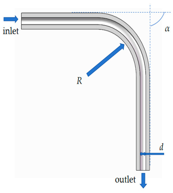
Figure 1.
Schematic diagram of bend tube.
The target y+ was less than 1. The mesh showed an average orthogonality of 0.90 and a maximum aspect ratio of 15.6, with hexahedral cells dominating the bend region. A mass flow inlet was set according to the hydrogen velocity and the tube inner diameter, as shown in Table 2. The turbulence intensity was 5% and the length scale was 0.21 mm. The pressure on the inlet was set as 3.2 MPa and it should be kept steady during the erosion process. The near-wall model was the k-ε turbulence model with enhanced wall functions. A total of 1000 time steps were taken at 0.1 s, with the DPM updated every 20 flow steps. The injection source injected 316 L particles with a diameter of 2.89 × 10⁻⁹ m, a density of 8027 kg·m−3 and a velocity of the given value from the inlet at a certain mass flow rate. The velocity and mass flow rate investigated in this study are shown in Table 2. The particle tracking used random-walk stochastic injection with a maximum of 10,000 steps and a step-size factor of 5. The boundary wall roughness was 0.0001 m. A total of 1000 time steps were taken at 0.1 s, with the DPM updated every 20 flow steps. Apart from the flow behavior of the hydrogen, there was interaction between the particle and the tube surface. The particle may collide with the tube surface and then rebound back to the hydrogen. Forder [26,27] proposed a model to describe the rebound behavior of the particle, as shown in Equations (8) and (9). The initial incidence angle was parallel to the straight portion of the bend tube (0-degree incidence). Because there were bends with a different bending radius and bending angles for the tube, the incidence angle of particles will change when erosion occurs in the bend tube. Based on Equations (8) and (9), the corresponding normal and tangential restitution coefficients at the bend location were calculated during erosion for the bends with a different bending radius and bending angles.
Table 2.
Simulation parameters for erosion process.
The effects of the geometry parameters (bend radius, bend angle and tube inner diameter) of the bend tube and the erosion parameters (time and velocity of hydrogen) on the erosion behavior were investigated in this study, as shown in Table 2.
εt and εn are the normal and tangential restitution coefficient, respectively, α is the particle impact angle.
3. Results and Discussion
Figure 2 shows the distributions of the pressure and erosion rate of the straight tube and bend tube. The pressure is 3.26 MPa and it keeps stable in the inlet and outlet of the tube for both the straight tube and bend tube, as shown in Figure 2a–c. The erosion rate of the straight tube is near-uniform-distributed and its maximum value is 2.08 × 10⁻⁶ kg/m2, as shown in Figure 2d. However, it is heterogeneous-distributed for the bend tube and the maximum value is located on the outer surface of the bend. The maximum value is 1.54 × 10⁻⁴ kg/m2, which is almost one hundred times that of the straight tube, as shown in Figure 2c. The flow velocity of the hydrogen is relatively uniform for the straight tube and the particles move towards the outlet along with the gas flow under the action of gas-phase drag force. The flow velocity on the outer surface of the bend is smaller than that on the inner surface. The particles around the outer surface show severe impact on the outer surface under the action of its own inertial force; as a result, the erosion’s concentrated area is generated on the outer surface of the bend. The erosion rate on the outer surface of the bend tube is much higher than that on other positions. Therefore, the maximum erosion rate on this position is investigated under different parameters.
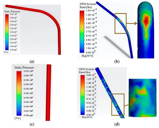
Figure 2.
(a) Pressure of bend tube; (b) erosion rate of bend tube; (c) pressure of straight tube; (d) erosion rate of straight tube (d = 3 mm, V = 170 m/s, R = 23.7 mm, α = 90).
3.1. Effect of Hydrogen Velocity
The effect of hydrogen velocity on the maximum erosion rate is shown in Figure 3 and Table 3. With the increased hydrogen velocity, the maximum erosion rate first slightly increases and then increases sharply when the hydrogen velocity exceeds the critical value of 100 m/s to 110 m/s. It shows a power law relationship between the hydrogen velocity and the maximum erosion rate when the hydrogen velocity exceeds the critical value. The erosion rate with a diameter of 3 mm is 1.75 × 10⁻⁵ at 35 m/s; it increases to over two times at 130 m/s and it increases about one order of magnitude at 170 m/s. Meanwhile, the critical value decreases with the decreased tube inner diameter, indicating that the smaller tube diameter is more sensitive to the erosion rate. For the bend tube with the small diameter, the gradient of shear stress on the tube surface increased, which increased the erosion efficiency per unit kinetic energy. The threshold under the small diameter was larger than that under the large diameter. With the hydrogen velocity of 170 m/s, the maximum erosion rate is 1.54 × 10⁻⁴ at a diameter of 3 mm while it drops to 5.21 × 10⁻⁶ at a diameter of 15 mm, resulting in a difference of about 30 times. The kinetic energy of hydrogen increases with the increased velocity and more impact energy is transferred to the surface of the bend tube. Additionally, more hydrogen molecules impact on the tube surface per unit time. At the same time, more particles also contribute to the erosion rate under high hydrogen velocity.
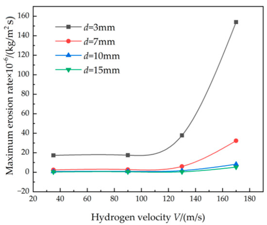
Figure 3.
Effect of hydrogen velocity on the maximum erosion rate (R = 23.7 mm, α = 90°).
Table 3.
Effect of hydrogen velocity on the maximum erosion rate.
For the bend tube with the small diameter, the gradient of shear stress on the tube surface increased, which increased the erosion efficiency per unit kinetic energy. The threshold under the small diameter was larger than that under the large diameter, as shown in Figure 3. Higher curvature reduced the impact angle θ, lowering the angular factor f(θ). The geometric parameters shift the pre-factor by altering both θ and the shear intensity on the tube surface without changing the exponent, whereas the particle properties modulate the peak pre-factor through Stokes number matching.
According to Figure 3, the power law relationship between the hydrogen velocity and the maximum erosion rate can be fitted using Equation (10), as shown in Table 4. The value of A decreased with the increased inner diameter while the power law index B increased. The value of A with an inner diameter of 3 mm was about two orders of magnitude larger than that with an inner diameter of 15 mm. It can be inferred that the erosion rate was quite sensitive to the inner diameter. The confidence intervals and fitting coefficient showed the good fitting results of the power law equations.
where Emax is the maximum erosion rate, V is the hydrogen velocity and A and B are constants.
Table 4.
Power law function of V-Emax under different tube diameters.
3.2. Effect of Bend Angle and Bend Radius
The effect of the bend angle and bend radius on the maximum erosion rate is shown in Figure 4 and Table 5. The maximum erosion rate almost decreases monotonically with the increased bend radius. With the bend angle of 25°, the maximum erosion rate is 1.24 × 10⁻⁴ at a bend radius of 15 mm while it decreases to 1.02 × 10⁻⁴ at a bend radius of 42 mm. The difference in the maximum erosion rate with the variation in the bend radius is much smaller than that with the hydrogen velocity. The Stokes number of the flow field decreases with the decreased bend radius, which leads to the decreased inertia force of the particles in the flow field, thus resulting in a concentrated erosion effect on the outer surface of the bend tube. The increased bend radius contributes to an increased Stokes number, which is beneficial for dispersed impact to the tube surface from the particles.
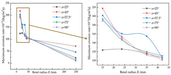
Figure 4.
Effect of bend radius on the maximum erosion rate (d = 3 mm, V = 170 m/s).
Table 5.
Effect of bend angle and bend radius on the maximum erosion rate.
Figure 5 shows the effect of the bend angle on the maximum erosion rate, which is different to the monotonic variation in the bend radius. The maximum erosion rate first increases obviously with the bend angle increasing from 25° to 45~57.5°, then it decreases slightly when the bend angle exceeds the value of 45~57.5°. The degree of change in the flow channel increases obviously when the bend angle increases from 25° to 45~57.5° and the severe phenomenon of secondary flow is generated. Therefore, the probability of mutual collision between the tube surface and the hydrogen as well as the particles increases, resulting in an increased maximum erosion rate. The further increased bend angle inversely decreases the mutual collision of the phenomenon of secondary flow. For the power law fit for the bent tube of 3 mm (R = 23.7 mm, α = 90°), the CI was 95% and the value of R-square was 0.998, which represented a good fit. It can be concluded that the dangerous window of the bend angle is 45~57.5° and it should be avoided for the bending process of the tube.
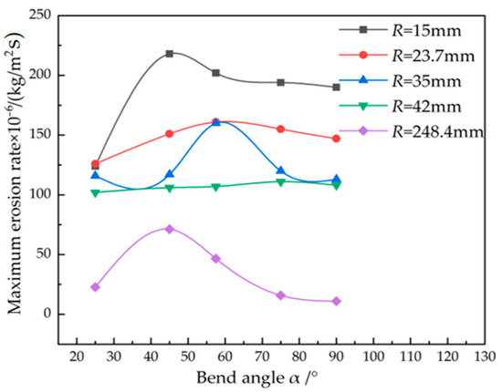
Figure 5.
Effect of bend angle on the maximum erosion rate (d = 3 mm, V = 170 m/s).
3.3. Effect of Erosion Time
For the actual service of the hydrogen aircraft engine, the hydrogen is the power source and its erosion effect on the bend tube is critical for safety. The effect of the erosion time on the maximum erosion rate is quite important for the prediction of the service life. The experiment of the long-time service of hydrogen erosion is extremely time-consuming and costly. The effect of the erosion time on the maximum erosion rate is shown in Figure 6 and Table 6. It is interesting that there is a linear relationship between the cumulative thickness loss and erosion time under a different bend radius and bend angle. A nanoscale micro-furrow will appear on the tube surface with the hydrogen impact at an early time and then these micro-pits interconnect to form micron-scale spalling pits, thus resulting in obvious erosion and material removal on the tube surface. With the increased erosion time, the vortex intensification effect within the pit further intensifies the local erosion rate. This linear relationship between the maximum erosion rate and erosion time is beneficial for the life prediction of the bend tube under hydrogen erosion, which will be discussed in Section 3.5.

Figure 6.
Effect of erosion time on the maximum erosion rate (d = 3 mm, V = 170 m/s).
Table 6.
Effect of erosion time on the maximum erosion rate.
3.4. Effect of Tube Inner Diameter
The maximum erosion rate decreases with the increased tube inner diameter, as shown in Figure 7. The descending range is quite large when the diameter ranges from 3 mm to 10 mm and then it is quite small with the further increased diameter. For the constant mass flow rate of the hydrogen gas, the increased diameter significantly decreases the hydrogen velocity. Additionally, the increased diameter also decreases the shear stress on the tube surface of the particles, which also decreases the erosion rate of the tube surface.
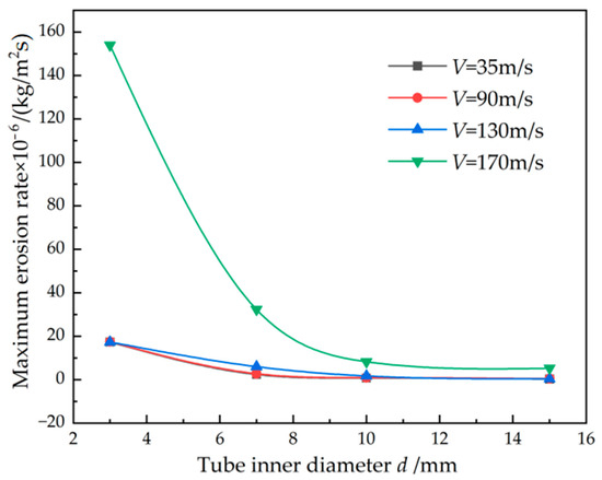
Figure 7.
Effect of tube inner diameter on the maximum erosion rate (R = 23.7 mm, α = 90°).
3.5. Prediction of Service Life
It can be seen that the geometry parameters and the erosion parameters both affect the erosion rate of the bend tube. It is vital to establish the prediction model of the service life of the bend tube under different parameters and provide guidance for the design, manufacturing and life assessment of the tube with hydrogen.
The relationship between the thickness loss (induced by the material removal from hydrogen erosion) and maximum erosion rate is shown in Equation (11). For the hydrogen flow behavior of the bend tube, the decreased thickness of the tube will change the stress state in three directions, thus affecting the service life of the tube. In this study, fourth strength theory is adopted to describe the effect of the thickness loss on the stress state of the bend tube.
where Δb is the thickness loss, Emax is the maximum erosion rate and ρt is the density of the steel tube.
The stress in three directions with hydrogen flow inside the tube can be calculated with Equations (12)–(14):
where σt, σa and σr are the stress in the tangential, axial and radial directions of the tube, p is the pressure of the hydrogen and D and d are the outer diameter and inner diameter of the tube.
The equivalent stress of the tube can be calculated using fourth strength theory, as shown in Equation (15). The criterion for the safe service of the tube is that the equivalent stress is smaller than the yield strength of the tube material considering the safety factor. By submitting Equations (12)–(14) into Equation (15), the criterion and the minimum thickness for safe service can be obtained, as shown in Equations (16) and (17).
where σeq is the equivalent stress, σs is the yield strength of the tube material, [n] is the safety factor and bmin is the minimum thickness for safe service.
As discussed in Section 3.3, there is a linear relationship between the maximum erosion rate and erosion time. It should be noted that a linear relationship exists with the erosion time of 2 h. As the cost of hydrogen erosion to the bend tube is quite high, a long-term erosion process is quite difficult to conduct. The prediction of the service life in this study is based on the results of the short-term results. According to Equation (11), the thickness loss at different erosion times and parameters can be calculated, as shown in Figure 8. The linear function can be adopted to establish the quantitative relationship between the thickness loss and the erosion time, as shown in Equation (18). The thickness of the tube after the erosion process should be larger than the minimum thickness for safe service; therefore, the service life of the tube can be calculated, as shown in Equations (19) and (20). Table 7 shows the service life of the bend tube with different parameters. It can be seen that the bend radius and bend angle obviously change the service life of the tube with constant hydrogen velocity. However, the safety factor slightly affects the service life of the tube.
where bt is the thickness loss at time t, m and n are the slope and intercept of the fitted linear function under different parameters and b0 is the initial thickness before erosion.
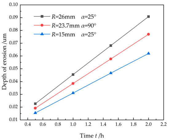
Figure 8.
Effect of erosion time on thickness loss (d = 3 mm, V = 170 m/s).
Table 7.
Service life of the bend tube with different parameters (d = 3 mm, V = 170 m/s).
It can be seen from Equation (20) and Table 7 that the variation in the safety factor will not alter the change rule of the parameters. The safety factor is set as 1 for the investigation into the effect of the parameters on the service life of the tube. Figure 9 and Figure 10 show the effect of the hydrogen velocity and tube inner diameter on the service life. The service life decreases dramatically with the increased hydrogen velocity and this descending range increases with the increase in the tube diameter. The service life is 112,172 h at 35 m/s while it decreases to 12,601 h at 170 m/s for the tube diameter of 3 mm. The service life increases with the increased tube inner diameter as the hydrogen velocity decreases obviously with the increased tube inner diameter under the constant mass flow rate of the hydrogen gas. The effect of the bend radius and bend angle is similar to that in Section 3.2. The service life increases with the increased bend radius; however, it shows a minimum value at a certain bend angle, as shown in Figure 11. For example, the service life is 15,649 h at the bend angle of 25° and it decreases to 8901 h at the bend angle of 45°.

Figure 9.
Effect of hydrogen velocity on the service life (R = 23.7 mm, α = 90°).
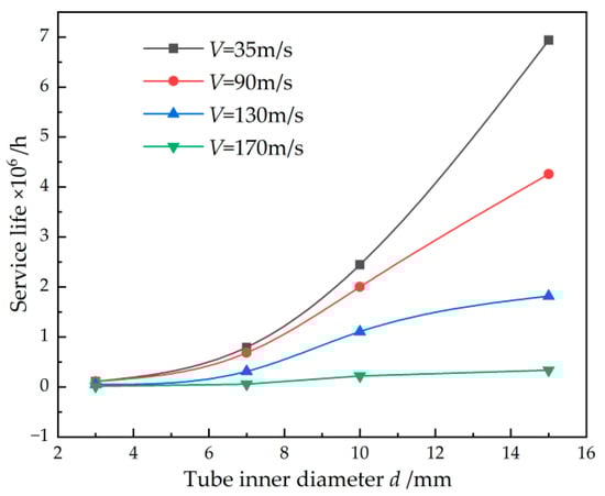
Figure 10.
Effect of tube inner diameter on the service life (R = 23.7 mm, α = 90°).
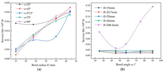
Figure 11.
(a) Effect of bend radius on the service life and (b) effect of bend angle on the service life (d = 3 mm, V = 170 m/s).
4. Experiment
The experimental set-up of the hydrogen erosion process is shown in Figure 12. The inner diameter and thickness of the tube were 3 mm and 0.5 mm. Hydrogen of 99.99% purity was used and the pressure on the inlet was 3.26 MPa. Two pressure transducers were adopted on the inlet and outlet to monitor the pressure. A flowmeter was positioned on the outlet of the hydrogen to monitor the mass flow rate. Four bend tubes of the stainless steel tube were connected with a different bend radius and bend angle. Each bend tube was removed for the analysis of the thickness and hardness after half an hour, and the effect of the erosion time on the variation in the thickness and hardness can be obtained. The experimental parameters were the same as the simulation.
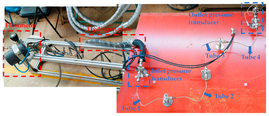
Figure 12.
Experimental setup of the hydrogen erosion process.
Figure 13 shows the comparison between the experimental pressure and simulated pressure. The simulated value located at the error bar of the experimental value can be seen. The error bar of the experimental value was inevitable during the long-time erosion process of the hydrogen. The pressure during the hydrogen erosion process was monitored and the average value as well as its standard deviation were calculated. The size of the throttle was calculated based on the diameter of the bend tube; however, there are four bend tubes in the experiment. The bend radius and bend angle both affected the flow behavior of the hydrogen, thus changing the pressure in the outlet direction.
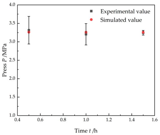
Figure 13.
Comparison between experimental pressure and simulated pressure.
The hydrogen erosion induced material removal on the surface of the bend tube and thickness loss, as shown in Equation (10). The thickness loss was quite small under the hydrogen erosion with the time of 1 to 2 h. The thickness variation of only several micrometers cannot be precisely obtained with the general equipment for the thickness measurement. Several samples around the bend corner of the tube were machined with a wire cutting machine and the thickness variation was measured using microscopy (OLYMPUS DSX500, OLYMPUS, Tokyo, Japan). For each sample, five points were measured and the average value as well as its standard deviation were calculated. Figure 14 shows the erosion depth of the bend tube with different parameters. The erosion depth increased with the increased erosion time and it varied under different parameters.

Figure 14.
Erosion depth of the bend tube with different parameters: (a) R = 26 mm, α = 25°; (b) R = 23.7 mm, α = 90°; (c) R = 15 mm, α = 25°.
To quantitatively describe the accuracy of the simulated results, the error between the experimental and simulated values was calculated. If the simulated value is located within the error bar of the experimental value, it indicates that the simulation agreed with the experiment. Only when the simulated value was beyond the error bar of the experimental value was the error calculated using Equation (21). Figure 15 shows the comparison between the experimental and simulated erosion depth. Most of the simulated values located within the error bar and the maximum error were 9.4% with the bend radius of 23.7 mm, bend angle of 90° and erosion time of 1.5 h. Therefore, it can be concluded that the simulated results agreed with the experiment.
where λmax and λmin are the maximum and minimum value of the experimental error bar, λave is the average value of the experiment and λs is the simulated value.
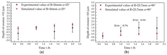
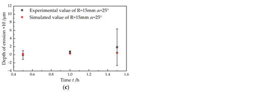
Figure 15.
Comparison between experimental and simulated erosion depth: (a) R = 26 mm, α = 25°; (b) R = 23.7 mm, α = 90°; (c) R = 15 mm, α = 25°.
After the measurement of the thickness variation, a Vickers hardness test was conducted using the hardness tester (KHVS-1000MT, Shance, Shanghai, China). The hardness variation for both the straight tube and the bend tube was measured. It was known that the hardness was positively related to the yield strength of the bend tube. Therefore, the hardness measurement was to investigate the variation in the mechanical properties of the bend tube after hydrogen flow. Four points of each sample were tested and the average value as well as its standard deviation were calculated. The load was 500 g and the holding time was 10 s. Figure 16 shows the hardness variation in the straight tube and bend tube under different erosion times. The hardness decreased obviously after the hydrogen erosion process and it slightly decreased further with the increased erosion time for both the straight tube and bend tube. The initial value of the straight tube was 249.5 HV while it was 211.9 HV for the bend tube, indicating that the bend process caused a hardness decrease. The hardness decreased from 249.5 HV to 170.8 HV after erosion for 2 h for the straight tube, resulting in a 31.5% decrease in the hardness. For the bend tube, the hardness decreased from 211.9 HV to 137.5 HV, leading to a decrease of 35.1%. It can be inferred that the bend tube was more sensitive to the hardness decrease after the hydrogen erosion process.
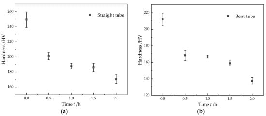
Figure 16.
Hardness variation in (a) straight tube and (b) bend tube (d = 3 mm, V = 170 m/s, R = 15 mm, α = 25°).
5. Conclusions
- (1)
- A CFD-DPM coupled model was established in this study and the bidirectional coupling between the continuous gas phase and discrete particle phase was considered, including the fluid flow field model, discrete particle motion model and erosion model.
- (2)
- The effect of the parameters on the maximum erosion rate of the tube was investigated. The maximum erosion rate first slightly increases and then increases exponentially with the increased hydrogen velocity. It increased linearly with the increase in the erosion time. The dangerous window of the bend angle was 45~57.5° and it should be avoided for the bending process of the tube.
- (3)
- The relationship between the thickness loss induced by the hydrogen erosion and maximum erosion rate was established. Fourth strength theory was adopted and the prediction model of the service life of the tube was established. The service life of the tube was quite sensitive to the hydrogen velocity and erosion time.
- (4)
- The experiments were conducted and the simulated results agreed with the experiments. The hardness of the tube decreased obviously after the hydrogen erosion process and it slightly decreased further with the increased erosion time.
Author Contributions
Conceptualization and writing, T.Z. and X.L.; experimentation and methodology, F.P. and W.X.; resources and data analysis, Z.S.; conceptualization and reviews, T.Z. All authors have read and agreed to the published version of the manuscript.
Funding
This research was funded by the Natural Science Foundation of Changsha (kq2402213), Cooperative Project with Hunan Institute of Power Machinery, China Aero Engine Corporation (KY104420240540), State Key Laboratory of Precision Manufacturing for Extreme Service Performance, Central South University (ZZYJKT2024-08) and Fundamental Research Funds for the Central Universities of Central South University (1053320240413, 1053320230358).
Data Availability Statement
The original contributions presented in this study are included in the article. Further inquiries can be directed to the corresponding author.
Conflicts of Interest
Authors Fuxia Peng and Wei Xiao are employed in China Aero Engine Corporation. Author Zhiji Song is employed in Zhejiang Dongou Filter Machinery Manufacturing Co., Ltd. The authors declare no conflicts of interest. The funders had no role in the design of the study; in the collection, analyses or interpretation of data; and in the decision to publish the results.
References
- Zhang, Q.; Chen, D.; Ding, L. Study on failure analysis and erosion wear of four-way cross in high-pressure gas well test process. Eng. Fail. Anal. 2025, 167, 109053. [Google Scholar] [CrossRef]
- Sun, Y.H.; Cheng, Y.F. Thermodynamics of spontaneous dissociation and dissociative adsorption of hydrogen molecules and hydrogen atom adsorption and absorption on steel under pipelining condition. Int. J. Hydrogen Energy 2021, 46, 34469–34486. [Google Scholar] [CrossRef]
- Wu, W.; Zhang, X.; Li, W. Effect of hydrogen trapping on hydrogen permeation in a 2205 duplex stainless steel: Role of austenite–ferrite interface. Corros. Sci. 2022, 202, 110332. [Google Scholar] [CrossRef]
- Abdo, H.S.; Seikh, A.H.; Alharbi, H.F.; Mohammed, J.A.; Soliman, M.S.; Fouly, A.; Ragab, S.A. Tribo-Behavior and Corrosion Properties of Welded 304L and 316L Stainless Steel. Coatings 2021, 11, 1567. [Google Scholar] [CrossRef]
- Wang, G.; Gao, Q.F.; Kou, L.F. Study on liquid-solid jet erosion characteristics of 316L stainless steel. J. Mech. Sci. Technol. 2023, 37, 1871–1882. [Google Scholar] [CrossRef]
- Arabnejad, H.; Mansouri, A.; Shirazi, S.A. Development of mechanistic erosion equation for solid particles. Wear 2015, 332–333, 1044–1050. [Google Scholar] [CrossRef]
- Yang, Y.; He, M.; Yu, P.; Kan, C.; Wang, X.; Yu, X.; Sun, Z. Investigation on critical erosion of gas production channel for sand carrying during injection and production process in gas storage. Geoenergy Sci. Eng. 2024, 239, 212945. [Google Scholar] [CrossRef]
- Zamani, M.; Seddighi, S.; Nazif, R.H. Erosion of natural gas elbows due to rotating particles in turbulent gas-solid flow. J. Nat. Gas Sci. Eng. 2017, 40, 91–113. [Google Scholar] [CrossRef]
- Jia, W.L.; Zhang, Y.R.; Li, C.; Luo, P.; Song, X.Q.; Wang, Y.Z.; Hu, X.Y. Experimental and numerical simulation of erosion-corrosion of 90° steel elbow in shale gas pipeline. J. Nat. Gas Sci. Eng. 2021, 89, 103871. [Google Scholar] [CrossRef]
- Wee, K.S.; Yap, J.Y. CFD study of sand erosion in pipeline. J. Pet. Sci. Eng. 2019, 176, 269–278. [Google Scholar] [CrossRef]
- Zhu, L.; Li, L.; Luo, J.; Han, Z.; Xie, S.; Yu, T.; Liu, Q. Investigating Erosion of String in Underground Hydrogen Storage under High Flow Velocity. Processes 2023, 11, 2894. [Google Scholar] [CrossRef]
- Abrofarakh, M. Analysis of elbow erosion in natural gas–hydrogen pipelines under dense and pseudo-dense phase flow: A CFD-DEM (gas–solid flow) study. Comput. Part. Mech. 2025, 1–15. [Google Scholar] [CrossRef]
- Pereira, G.C.; Souza, F.; Martins, D. Numerical prediction of the erosion due to particles in elbows. Powder Technol. 2014, 261, 105–117. [Google Scholar] [CrossRef]
- Alexey, M.; Elena, V.; Galina, R. Numerical analysis of the brittle strength of welded pipelines with corrosion metal loss in the transportation of blends of natural gas with hydrogen. J. Weld. World 2023, 67, 2803–2809. [Google Scholar]
- Wen, Y.; Koyama, M.; Hojo, T. Plasticity-induced Hydrogen Desorptions Associated with Hydrogen-assisted Martensitic Transformation and Deformation Twinning in Austenitic Stainless Steels:Regular Article. ISIJ Int. 2024, 64, 474–481. [Google Scholar] [CrossRef]
- Fu, Z.; Jiang, L.; Sun, Y. Cyclic deformation and microstructural evolution of 316L stainless steel with pre-charged hydrogen. Int. J. Fatigue 2024, 184, 108311. [Google Scholar] [CrossRef]
- Nygren, K.E.; Nagao, A.; Wang, S.; Sofronis, P.; Robertson, I.M. Influence of internal hydrogen content on the evolved microstructure beneath fatigue striations in 316L austenitic stainless steel. Acta Mater. 2021, 213, 116957. [Google Scholar] [CrossRef]
- Nguyen, T.T.; Park, J.; Nahm, H.S. Effect of hydrogen on tensile flow and failure mechanism of low nickel-type 316L austenitic stainless steel. J. Mech. Sci. Technol. 2019, 33, 5843–5849. [Google Scholar] [CrossRef]
- António, M.; Jesus, J.; Vilhena, L. Influence of hydrogen embrittlement on the fatigue behaviour of 316L stainless steel welded joints. Int. J. Hydrogen Energy 2025, 128, 534–543. [Google Scholar] [CrossRef]
- Shengquan, H.; Yanran, M.; Dan, Z.; Dazhao, S.; Xueqiu, H.; Siyu, L.; Jia, W. Fatigue crack extension and acoustic emission response law of 316L austenitic stainless steel by hydrogen charging. Theor. Appl. Fract. Mech. 2024, 138, 104983. [Google Scholar]
- Zhu, H.; Qi, Y. Numerical investigation of flow erosion of sand-laden oil flow in a U-bend. Process Saf. Environ. Prot. 2019, 131, 16–27. [Google Scholar] [CrossRef]
- Farokhipour, A.; Mansoori, Z.; Saffar-Avval, M.; Ahmadi, G. 3D computational modeling of sand erosion in gas-liquid-particle multiphase annular flows in bends. Wear 2020, 450–451, 203241. [Google Scholar] [CrossRef]
- Oka, Y.; Mihara, S.; Yoshida, T. Impact-angle dependence and estimation of erosion damage to ceramic materials caused by solid particle impact. Wear 2008, 267, 129–135. [Google Scholar] [CrossRef]
- Wang, K.; Li, X.; Wang, Y.; He, R. Numerical investigation of the erosion behavior in elbows of petroleum pipelines. Powder Technol. 2017, 314, 490–499. [Google Scholar] [CrossRef]
- Zeng, D.; Zhang, E.; Ding, Y.; Yi, Y.; Xian, Q.; Yao, G.; Zhu, H.; Shi, T. Investigation of erosion behaviors of sulfur-particle-laden gas flow in an elbow via a CFD-DEM coupling method. Powder Technol. 2018, 329, 115–128. [Google Scholar] [CrossRef]
- Liu, Q.; Luo, Z.H. CFD-VOF-DPM simulations of bubble rising and coalescence in low hold-up particle-liquid suspension systems. Powder Technol. 2018, 339, 459–469. [Google Scholar] [CrossRef]
- Liu, P.; Wang, Y.; Yan, F.; Nie, C.; Ouyang, X.; Xu, J.; Gong, J. Effects of Fluid Viscosity and Two-Phase Flow on Performance of ESP. Energies 2020, 13, 5486. [Google Scholar] [CrossRef]
Disclaimer/Publisher’s Note: The statements, opinions and data contained in all publications are solely those of the individual author(s) and contributor(s) and not of MDPI and/or the editor(s). MDPI and/or the editor(s) disclaim responsibility for any injury to people or property resulting from any ideas, methods, instructions or products referred to in the content. |
© 2025 by the authors. Licensee MDPI, Basel, Switzerland. This article is an open access article distributed under the terms and conditions of the Creative Commons Attribution (CC BY) license (https://creativecommons.org/licenses/by/4.0/).