Abstract
A novel design of a proton exchange membrane electrolyzer is presented. In contrast to previous designs, the flow field plates are round and oriented horizontally with the feed water entering from a central hole and spreading evenly outward over the anode flow field in radial, interdigitated flow channels. The cathode flow field consists of a spiral channel with an outlet hole near the outside of the bipolar plate. This results in anode and cathode flow channels that run perpendicular to avoid shear stresses. The novel sealing concept requires only o-rings, which press against the electrolyte membrane and are countered by circular gaskets that are placed over the flow channels to prevent the membrane from penetrating the channels, which makes for a much more economical sealing concept compared to prior designs using custom-made gaskets. Hydrogen leaves the electrolyzer through a vertical outward pipe placed off-center on top of the electrolyzer. The electrolyzer stack is housed in a cylinder to capture the oxygen and water vapor, which is then guided into a heat exchanger section, located underneath the electrolyzer partition. The function of the heat exchanger is to preheat the incoming fresh water and condense the escape water, thus improving the efficiency. It also serves as internal phase separator in that a level sensor controls the water level and triggers a recirculation pump for the condensate, while the oxygen outlet is located above the water level and can be connected to a vacuum pump to allow for electrolyzer operation at sub-ambient pressure to further increase efficiency and/or reduce the iridium loading.
1. Introduction
As intermittent energy sources like wind and solar power are becoming cheaper and more widely used, there is a growing need for seasonal storage of excessive energy for use in days of dunkelflaute, i.e., dark doldrums. Currently, countries with widespread wind and solar power experience negative electricity prices because the supply sometimes exceeds the demand, while during periods of dunkelflaute, electricity prices reach record highs. A further deployment of wind and solar, as is foreseen to decarbonize the energy system, will worsen such scenarios. Moreover, in countries with large amounts of hydropower, part of the energy usually has to be curtailed [1]. This results in an economic opportunity—and even need—to store excessive solar, wind or hydro energy, either in (flow) batteries or in the form of hydrogen created via water electrolysis, which can then be converted back into electricity via fuel cells.
The most common types of large-scale electrolyzers are the mature alkaline electrolyzer, the more recent proton exchange membrane (PEM) electrolyzer, and the solid oxide electrolyzer, which is mostly in the development phase. Each of these technologies has different advantages and disadvantages. Unique features of the PEM electrolyzer include the quick start-up time, the high hydrogen pressures exceeding 100 bars, the high hydrogen purity and its modularity [2]. Drawbacks of the PEM technology are the need for precious metals like iridium and platinum as catalysts and titanium as bipolar plates [2] which are sometimes coated to prevent the formation of an oxide layer, and there have been efforts to replace the titanium with cheaper materials [3]. Consequently, the capital expenses to install a PEM system are higher compared to an alkaline electrolyzer system.
On the other hand, the efficiency has a strong influence on the final price of hydrogen, and if the efficiency of a PEM system exceeds that of an alkaline system, this can still become the winning technology, provided the iridium loading can be substantially decreased [4]. The modularity of PEM electrolyzers makes them suitable for small-scale as well as large-scale operation. A recent publication outlines the required improvements on a component level for the deployment of PEM electrolyzers in the required gigawatt scale [5]. While different configuration variations and methods of operation were summarized, the overall design options were not taken into consideration.
Another promising technology is the anion exchange membrane electrolyzer (AEM), which is a hybrid between the cheaper alkaline electrolyzer, but entailing an ion exchange membrane, and small-scale electrolyzers as well as industrial-scale electrolyzers are currently offered. According to the International Renewable Energy Agency (IRENA), their energy consumption is slightly higher than that of PEM electrolyzers [6], and degradation issues are more severe compared to competing technologies [7].
In a proton exchange membrane electrolyzer, water is split into oxygen, protons, and electrons on the anode side. The protons migrate through the electrolyte membrane, which is proton-conductive and electron-repellent, so that the electrons travel through an outer electrical circuit, driven by a cell potential.
At the cathode, electrons and protons recombine to form hydrogen, according to
Hence, the overall reaction for the electrolysis process is the decomposition of water into hydrogen and oxygen:
The polymer electrolyte membrane is not only proton-conductive but also allows for water permeation, and this means that the hydrogen is mixed with water vapor at the cathode outlet. It was recently proposed to add a proton-conductive graphene oxide layer to the membrane to stabilize the membrane and thus allow for thinner membranes and prevent water permeation to the cathode side [8].
The anode typically requires iridium as a catalyst, one of the scarcest and most expensive elements on earth, while on the cathode side, platinum is used [9]. The need for iridium in particular makes PEM technology expensive. Thus, there is a need to increase PEM electrolyzer efficiency and reduce the amount of iridium needed per kilowatt installed power. This can be achieved via improvements on a component level, but also via an improvement of the overall electrolyzer design to increase the system efficiency and the balance of the plant.
2. Previous PEM Electrolyzer Designs
The pioneers in PEM electrolysis (earlier called solid polymer electrolyzers, SPEs) were General Electric, who first built a rectangular stack in cross-flow design [10]. The commercial Membrel electrolyzer design by ABB was investigated and tested by Stucki et al. [11]. The stack design appeared to be similar to the GE design with rectangular cells where the general flow direction is cross-flow. The authors measured a clear thinning of the membrane towards the water outlet and even the exhibition of hot spots where the membrane was thinnest at the anode outlet, which indicates that the flow distribution is important. Rasten et al. [9] included a detailed literature study in their work where they investigated different types of catalysts. This work was followed up upon by Marshall et al. [12] who tested different types of iridium alloys. Overall, there has been substantial effort in improving the catalyst layer and membrane materials.
There are various commercially available PEM electrolyzers, and in recent years, several large companies have joined the field. It is noted that the majority of the commercial units employ a rectangular or quadratic stack design. The electrolyzer stacks in the Silyzer design by Siemens comprise rectangular, vertically oriented cells [13]. Vertical plate orientations are known from alkaline electrolysis where gravity is used to keep hydrogen and oxygen product gases separated. By contrast, the small-scale PEM electrolyzer from the S-series by NEL that produces up to 1.05 Nm3/h or 2.28 kg/d consists of a cylindrical stack with horizontal plates [14] while the larger MC series that can produce up to 492 Nm3/h consists of rectangular, horizontal plates [15]. NEL resulted from the alkaline electrolyzer manufacturer Norsk Hydro, Norway, and then acquired PEM technology from Proton Onsite, USA. While it is difficult to see from the schematics, the connector pipes appear to be at mid-height or near the top on the side of the rectangular (or quadratic) stack with no connectors on top.
Rectangular, horizontal plates are also employed by Bosch [16], where all the connector pipes are placed on top of the electrolyzer stack. These Hybrion PEM electrolysis stacks can produce up to 23 kg/h of hydrogen at 30 bar-g at a power rating of 1.25 MW and a specific power of around 50 kWh/kg hydrogen and maximum efficiency [16]. One kilogram of hydrogen is equivalent to 11.126 Nm3; hence, the maximum output of the Hybrion is 256 Nm3/h. The EX-2125D electrolyzer by Plug Power also employs quadratic, horizontal plates, and it produces up to 990 Nm3/h at up to 40 bar-g [17], which is expanded to 1989 Nm3/h in the EX-4250D system [18]. The electrical ratings of these two systems are 5 MW and 10 MW, respectively, and the efficiency is also around 50 kWh/kg hydrogen. Plug Power acquired the technology from Giner Inc., who had developed cylindrical stacks for small-scale applications and rectangular stacks for larger-scale ones.
Rectangular, horizontal cells are also employed by ITM Power as well as in the HyLIZER® series by Cummins (formerly Hydrogenics, Mississauga, ON, Canada) that produce up to 4000 N/h at 30 bar in the HyLIZER® 4000-30 system [19]. All these companies report efficiencies in the order of 50 kWh/kg hydrogen, while Cummins, which acquired alkaline technology from Hydrogenics (formerly Stuart Energy Systems, Mississauga, ON, Canada), reports efficiencies of 55–60 kWh/kg for the alkaline HySTAT ® electrolyzers, highlighting the trade-off between lower CAPEX versus higher OPEX for alkaline systems. Finally, British ITM Power offers the system Neptune V, which produces up to 1080 kg/d in eight rectangular stacks with horizontal plates at 30 bar at a rated capacity of 5 MW. The system power required including the balance of the plant is given as 55.9 kWh/kg [20].
As most of the above designs are fairly similar, it may be assumed that, with the exception of the Silyzer from Siemens, the stacks can operate at differential pressures, meaning that the hydrogen side is pressured while the oxygen side operates at ambient pressure. Generally, it appears that large-scale electrolyzers in the range of megawatt (MW) are currently made with rectangular designs.
Additional commercial manufacturers include HyStar in Norway, also employing rectangular stacks with horizontal cells and connections on the top, whose unique feature is that the water is fed to the cathode side such that it relies on water transport through the membrane, which was claimed to yield higher efficiencies because of the use of thinner membranes [21]. The listed power consumption is 49.8 kWh/kg–52.2 kWh/kg, and the output pressure of the hydrogen is 3.6 bar without additional compression [22]. Finally, the German manufacturer H-TEC Systems once offered small-scale PEM electrolyzers in the Series-S in the kW range yielding up to 2.37 kg/d at 30 bar, where the stack was rectangular and lay horizontally, apparently with all connectors in one end. The company is now called Quest One, and it offers industrial-scale PEM electrolyzers with similar specifications to the above.
The Honda system was designed for automotive applications with a hydrogen production pressure of up to 700 bar [23], but a low hydrogen production rate of up to 2.5 kg/d, suitable for automotive applications. This system is designed to operate at high differential pressure, meaning that the hydrogen pressure can far exceed the oxygen pressure, which is impossible with liquid alkaline technology. A snapshot from the Honda design is shown in Figure 1. The water enters at the upper left, and a mixture of excess water and oxygen leaves at the opposite end at the lower right of the top plate, while the hydrogen escapes from the center hole on top of the electrolyzer. For comparison, an exploded picture of the former Giner stack is shown in Figure 2.
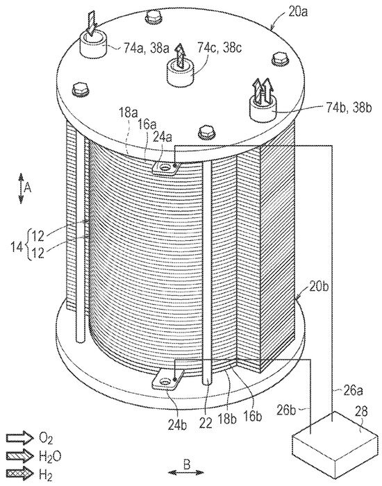
Figure 1.
Honda PEM electrolyzer stack [23].
Figure 2.
Giner PEM electrolyzer stack [24].
It can be seen that the water enters at the lower side of the round electrolyzer and a mixture of water (vapor) and oxygen leaves on the opposite, upper side, while in contrast to the Honda design, the hydrogen escapes from a smaller hole on the right side. Also different from the Honda design, there is a purging inlet for water on the opposite side from the hydrogen outlet. Having the water entering at one side and leaving on the opposite side causes an obvious problem at large scales: The water pressure is highest at the anode inlet, whereas it is lowest at the opposite end of the first cell inside the stack where the mixture of excess water, water vapor, and oxygen leaves the stack. Such an arrangement invariably leads to an uneven water distribution between all cells inside the stack, and this is likely to cause local cell overheating where the gas fraction is highest, and it is likely that this creates a limit on the size of this design. A better understanding of this problem might be attained by hydraulic network modeling as conducted by, e.g., Baschuk and Li [25].
Other design options include the horizontally oriented cylinders used in the GenHy® design by Millet et al. [26,27], which at first sight is similar to the Giner design, i.e., a (horizontal) cylinder with asymmetrical water feeding, and the Primolyzer design by IRD A/S in Denmark until around 2018. A detailed computational fluid dynamics study focusing on the latter design suggested severe flow maldistribution of water, which led to predicted hot spots and the understanding that for successful design, the water has to be uniformly distributed [28,29]. As the difference in density between the liquid water that is fed to the stack and the gaseous products is one thousand, the predicted volume fraction of the gas phase is substantial, and the multiphase flow leaving the electrolyzer can stretch over different flow regimes [30], from bubbly flow to annular flow. A summary of the different commercial PEM electrolyzer designs with key specifications is given in Table 1.

Table 1.
Key features of various commercial PEM electrolyzer designs in alphabetical order.
Other academic electrolyzer designs were investigated by Selamet et al. [34], who used a horizontal cylinder with vertical plates, similar to Millet et al. [26]. Briguglio et al. [35] employed a rectangular cell design with vertical plates and three-pass serpentine flow fields. Prior to that, Ito et al. [30] had studied the effect of the flow field channels in a rectangular cell on the fuel cell performance, and found that parallel channels, which obviously led to even flow distribution, had the best performance compared to single-pass or multi-pass serpentine channels. More recently, Wirkert et al. [36] presented a modular stack design in a pressure housing. The individual cells are rectangular and apparently have multi-pass serpentine flow channels. They reported a stack performance of more than 1.5 A/cm2 at an average cell voltage of 2 V.
The work presented here is based on the learnings from the IRD Primolyzer design [29]. An effort was made to have symmetrical water flow to avoid hot spots. Similar to the Honda design, the stack presented here is meant to operate at a differential pressure, meaning that the anode side can operate at or below ambient pressure while the cathode side can be pressured to take advantage of electrochemical compression [37]. The cathode side can be operated below ambient pressure to improve the performance and reduce the iridium loading, as will be described below.
3. Entrolyzer Design
3.1. Bipolar Plates
It was found in prior studies that it is beneficial to have even water flow distribution in every flow channel and ideally in every cell. The reason for this is the large density difference of three orders of magnitude between the feed water and the product gases. The IRD design Primolyzer was in part operating at a water stoichiometry of over 300, but the CFD simulations still suggested a large volume fraction of the gas phase, and, because the design was not symmetrical, gas build-up led to hot spots where the local temperature could be more than 10 °C higher than the nominal operating temperature [29]. Therefore, it was considered a necessity to have uniform water flow.
As a result, flow channels that spread radially outward from a central water feeding hole were chosen for the anode side, which led to a round plate design. The area of the flow channels was kept constant to allow easier manufacturing of the titanium bipolar plates and have low contact resistances. The resulting anode-side flow field is shown in Figure 3, left. The outgoing channels were spaced at 15 degrees, yielding a total of 24 outlet channels. However, a 30-degree section was left for the hydrogen outlet channel, and therefore, the final number of outlet channels was 22. The width of the outlet channels determines the water feeding hole in the center. The finest cutter for the titanium was 0.75 mm, but it was estimated that the channel width would then be around 1 mm. Thus, the minimum hole size would have a minimum circumference of 24 mm, resulting in a diameter of 7.64 mm. In order to have some channel spacing, the water feeding hole has a diameter of 10 mm. All channels have an initial depth of 0.5 mm.
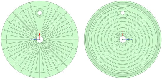
Figure 3.
Anode (left) and cathode (right) flow fields.
Similar to the Primolyzer design from IRD A/S, the anode flow field design was interdigitated [38] to enhance water transport to the catalyst layer. A study employing computational fluid dynamics (CFD) of a PEM fuel cell suggested that by employing interdigitated flow fields, a very low stoichiometry can be achieved [39]. The original design shown in Figure 3 had outlet channels that start close to the center.
However, upon reflection and a preliminary modeling study, it appears more beneficial to have short outlet channels that serve as ports and start at the diameter where the inlet channels end, only with a 7.5-degree offset. This may help to prevent water from short circuiting the cell. The spacing of the outlet sections was also 15 degrees. On the right side of Figure 1 is the hydrogen outlet opening, surrounded by a sealing ring groove. In the current, proof-of-concept (PoC) design, the active region has a diameter of 100 mm, determined by the size of the carbon fiber papers that were used as porous transport layers. The sealing width of the membrane was taken to be 8 mm, resulting in an outer plate diameter of 116 mm, while the membranes had an outer diameter of 120 mm.
Having decided on using radially outward, interdigitated flow channels for the anode side, it is obvious that the cathode-side hydrogen must be collected from inside the bipolar plate to prevent it from mixing with the oxygen, and therefore, the logical choice was a spiral flow field on the anode side. It is generally known that owing to the much more facile HER, the distribution of the hydrogen is less critical than uniform water feeding. A spiral flow field leaves the options of having the hydrogen outlet hole either near the center of the cell or near the outer edge. While in the Honda design, it was proclaimed that collecting the hydrogen from a central pipe in the electrolyzer was beneficial, the decision for the Entrolyzer design was to have the hydrogen escape the pipe near the edge of the plate, as it is here, where the metal bolts compress the stack. For the design of the spiral flow field, a two-point Archimedean spiral with a distance of 5 mm was chosen. The final design of the cathode flow field is shown in Figure 3, right. Near the outer edge is the groove for the outer sealing ring, and there is another groove at the inner diameter to seal the hydrogen against the inlet water channel.
Apart from the perfect symmetry in the water distribution, an advantage of this channel design is that the anode and cathode channels run perpendicularly, which results in very small sections of unsupported membranes (<1 ). This will also prevent shear stresses when the stack is compressed for high-pressure hydrogen generation. Similar to the Honda PEM stack, this stack is meant to operate at a high pressure difference between the cathode side and anode side.
3.2. Sealing Concept
It was shown above that each bipolar plate is sealed by three o-rings, one on the anode side around the hydrogen outlet, and two on the cathode side around the water inlet and at the outer edge. However, it must be ensured that on the opposite side of each sealing ring, the membrane is not pushed into the flow channels. This becomes obvious when inspecting the radial anode channels in Figure 4 in the regions opposite the cathode sealing rings. Therefore, metal gaskets were placed over the flow channels to counter the sealing rings, and it emerged that these would also have to be made out of titanium as stainless steel sheets caused severe corrosion. It was only possible to allocate Grade 2 titanium plates of 0.3 mm thickness, while Grade 5 would require a minimum thickness of 0.5 mm. The cost increment of the latter is less than 10 %, and therefore, in the future, provisions will be made to allow for the thicker Grade 5 sheets, unless thinner sheets can be allocated.
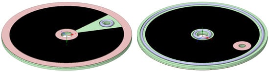
Figure 4.
Anode (left) and cathode (right) bipolar plate with sealing gaskets (red), porous transport layer (black), and sealing rings (blue).
Care must be taken to ensure that the final height of the metal gaskets is the same as the porous transport layers, accounting for around 20 % of compression. Thus, the area of the gaskets that can best be seen at the outer edge in Figure 4 was machined down by 150 microns, leaving a channel depth of 350 microns below. In the PoC design, we used wet proofed carbon fiber papers (Toray 060) with a thickness of 190 microns, thus allowing for 40 microns of compression. The bipolar plates, including the sealing gaskets, the sealing ring and the porous transport layer, are shown in Figure 4.
The porous transport layers had to be cut to shape with a carpet knife. The active membrane area was similar in shape to the anode-side porous transport layer. The active membrane area starts at an inner diameter of 20 mm, leaving a 5 mm sealing area. The outer active diameter is 100 mm, and the cut-out section is 30 degrees. This results in an active area of around 69.1 cm2 per single cell. This is nearly identical to the Primolyzer by IRD A/S, and this coincidence will make a performance comparison easier. As the 30-degree section is an unused membrane, it should be reduced when the design is scaled up to a larger outer diameter, leading also to a higher number of radial water channels and naturally to a larger inlet hole for the feeding water.
It is noted that the two holes in every bipolar plate allow for perfect centering and aligning of the bipolar plates, which is clearly needed in this design. By constructing two metal pins of appropriate diameter, it was possible to perfectly align the bipolar plates when assembling the stack.
For the PoC design, a 5 mm thick Grade 5 titanium plate of 500 mm by 500 mm dimensions was purchased. This allowed for the manufacturing of 16 plates in total, resulting in 14 bipolar plates and 2 monopolar end plates. Hence, a stack with 15 cells could be built out of one titanium plate. Consequently, the total active area was around 1036 cm2. However, it can be seen below that owing to the modularity of our design, up to 20 MEAs could be placed into the same housing, yielding an active area of up to 1382 cm2.
The IRD electrolyzer of similar size with seven cells showed a performance of 2 V at 1.0 A/cm2 and 2.5 V at 4 A/cm2. The latter performance point in this electrolyzer would lead to around 10 kW at 4 A/cm2. Owing to the modular design, this stack can be easily scaled up. Also, if operated at 4 A/cm2, the stack would consume a total of 4144 A, producing 0.0215 mole/sec of hydrogen according to Faraday’s law and neglecting internal losses. The produced volumetric flow of hydrogen is then 1.86 Nm3/h or a mass of 3.71 kg/d.
The electrolyzer stack with 15 active cells is shown in Figure 5. The plates are transparent so that the flow channels can be seen.
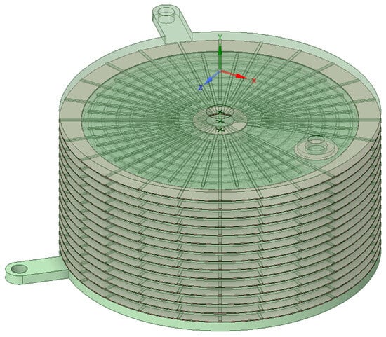
Figure 5.
Electrolyzer stack with 15 cells.
3.3. Stack Design
It is desirable to collect the oxygen produced, which will be flowing radially outward. Moreover, the anode exhaust stream containing excess water, water vapor, and oxygen is the largest thermal mass exiting the electrolyzer, and for this reason, it was planned to place a heat exchanger below the electrolyzer stack where the incoming water is preheated by the anode exhaust stream and the condensing water vapor. The integrated heat exchanger will also serve as a phase separator in that the excess water and the condensate will accumulate at the bottom, with the water level being monitored by a level switch which triggers a recirculation pipe, and therefore the gas/vapor phase will escape through a dedicated outlet. For the recirculation pump, a ULKA Pump Model EFP 5, frequently used in coffee machines, has been identified. The retail cost is around USD 30 and therefore almost negligible. For the level switch, we purchased a model from the NV series by Kobold (https://www.kobold.com/), and for a single unit, the retail costs are in the order of USD 200–300, but cheaper units could be found. In mass production, the cost of the level switch and the recirculation pump will become negligible compared to the stack cost.
Another advantage of internally separating the phases in this way is that now a vacuum pump can be connected to the anode-side outlet. The reasoning behind this will be described below.
The modules of the electrolyzer and the integrated heat exchanger were mounted onto the top plate of the electrolyzer and pushed down into the vessel. A close-up of the electrolyzer assembly is shown in Figure 6. It can be seen that the threadings at the lower end of the electrolyzer assembly bolts are extended in order to allow for the placement of washers with a negative thermal expansion coefficient that can compensate for the thermal expansion of the electrolyzer when it is heated up to the operating temperature. Such washers are offered by Allvar [40].
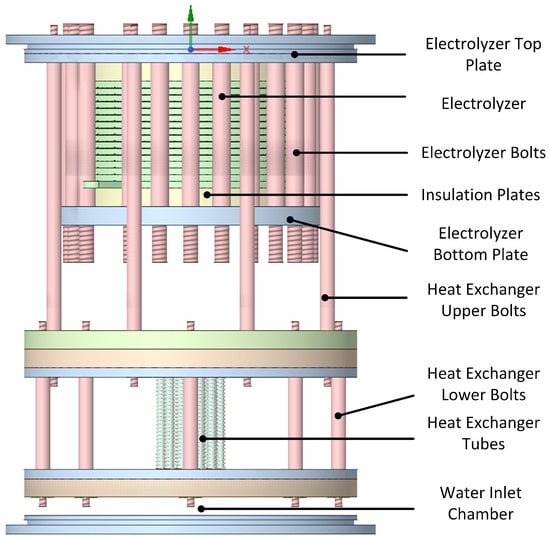
Figure 6.
Side view of the electrolyzer assembly.
The lower part of the heat exchanger consists of two metal plates where the lower one holds the sealing rings. The middle section of the lower surface of the lowest plate is shaped concavely to let the incoming water push out any residual air during start-up.
There are 24 tubes in the heat exchanger, calculated using the transfer area required to heat up incoming water at room temperature to the desired operating temperature of 80 °C. In the current PoC design, there are four large sealing rings placed in the upper and lower plates of the entire vessel as well as at the upper and lower parts of the heat exchanger part, pressing against the vessel. Owing to the limited availability of the required sealing ring sizes, all of them were the same size, which meant that the sealing rings around the heat exchange plates had to be pushed down nearly the entire length of the vessel. This naturally caused problems in the assembly, and an obvious improvement will be to make the plates of the heat exchanger with stepwise smaller diameters and also create stepwise reductions in the inner vessel diameter from top to bottom. This improvement was left for the prototype stage. In the current build, these four outer sealing rings had dimensions of 2 mm by 175 mm from HUG-Technik (https://www.hug-technik.com/). The next sizes of sealing rings in that line have an inner diameter of 170 mm or 180 mm. This poses limitations in the design of a PoC or prototype, but should not be a problem in a commercial unit. An angled view of the assembly is shown in Figure 7.
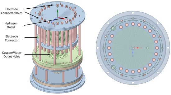
Figure 7.
Side view of the electrolyzer assembly and view through the top plate.
In the top plate are the electrode connectors and the hydrogen outlet. It can be seen that the number of bolts that compress the electrolyzer stack is maximized by using the minimum possible distance for M8 screws. The number and size of the screws have not been calculated, but the Honda design suggests that they should be maximized. The monopolar plates at the bottom and top of the electrolyzer contain extensions to connect to the stack electrodes. Figure 7 also shows a view through the transparent top plate. It can be seen that the hydrogen outlet hole is located where the compression is maximum, which is important when the cathode-side pressure is high.
3.4. Cylinder Design
The electrolyzer assembly is housed in a cylinder that contains the various inlet and outlet connections. The water outlet is located directly above the water inlet port, which are internally separated by the lowest two plates shown in Figure 6. This will be the coldest region in the electrolyzer, and therefore, the condensed water will leave the electrolyzer at the minimum possible temperature, leaving the heat inside the electrolyzer and thereby minimizing the entropy production. The CAD drawing of the cylinder is shown in Figure 8.
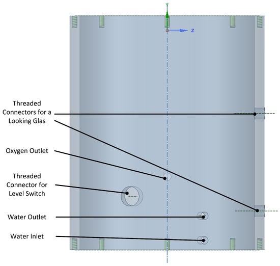
Figure 8.
Outer vessel with the connection holes.
The current vessel is 260 mm high and has an outer diameter of 200 mm. Hence, together with the end plate, the electrolyzer is 270 mm high, yielding a volume of 8.48 L. Assuming a performance as above, this would result in a volumetric power density just over 1 kW/L, which can be easily scaled up. There are several advantages to placing the electrolyzer inside a cylinder:
- The electrolyzer and the heat exchanger constitute an integrated, compact design while keeping thermal losses at a minimum.
- In contrast to the aluminium cylinder made for this PoC, the cylinder can also be made out of a hard plastic like POM to keep the cost and weight low and further reduce thermal losses.
- The electrolyzer is shielded from harsh environmental conditions that can occur when it is placed offshore.
- The pressure inside the electrolyzer vessel can be reduced with the help of a vacuum pump.
The name of the design presented here, Entrolyzer, results from the fact that an effort is made to minimize entropy generation. The phases are separated internally, and the condensed water exits from the point with the lowest temperature, the inlet water. Moreover, an MEA that includes a graphene oxide layer on the cathode side as proposed by Berning and Bessarabov [39] could help to purify the hydrogen internally, further reducing the entropy production.
3.5. Sub-Ambient Anode Pressure Operation
It was mentioned above that a key feature of the here-presented design is the ability to operate the anode side at a sub-ambient pressure by attaching a vacuum pump and a pressure-controlling valve to the anode gas outlet. The reasoning behind this is as follows: The water saturation pressure at around 81.3 °C is 50 kPa. At the anode outlet is a binary mixture of oxygen and water vapor, and assuming thermodynamic equilibrium, at 1 bar total pressure, this mixture would then consist of even molar amounts of oxygen and water vapor. By reducing the total pressure to 60 kPa, i.e., by operating the anode side in a partial vacuum, and assuming thermodynamic equilibrium, the water pressure would still be at 50 kPa, and therefore, the oxygen pressure can only be 10 kPa. Thus, the molar composition between water vapor and oxygen would increase to 5:1. If the total pressure were further reduced to 55 kPa, then this ratio would increase to 10:1, which is one order of magnitude larger than operating at one bar. These values are summarized in Table 2.
Table 2.
Dependency of the anode exhaust gas composition on the total pressure at thermodynamic equilibrium.
In general reaction chemistry and in particular in electrochemical half-cell reactions that are governed by the Butler–Volmer equation, the ratio of the concentrations between the reactant and product plays an important role in the determination of the activation overpotential, and therefore, a reduction in the activation can be expected, or, alternatively, a reduction in the catalyst loading might be possible. The effect of elevated-pressure electrolyzer performance for equal anode- and cathode-side pressure was measured by Weber et al. [41]. Preliminary CFD simulations of the electrolyzer design presented here suggested a clear increase in the concentration ratio with reduced pressure.
3.6. Key Features
In summary, the Entrolyzer design described above has the following key features compared to existing commercial designs:
- Symmetric, radially outward water feeding, trying to avoid hot spots to reduce degradation.
- Circular channels on the cathode side, avoiding shear stresses.
- Small sealing areas due to the round design; only o-rings are required.
- Small (<1 mm2) areas of unsupported membrane where the membrane is exposed on both sides to flow channels, leading to lower contact resistances.
- All cells can be fed evenly due to a very even pressure drop across all plates.
- A round plate design allows for uniform compression.
- Integrated heat exchanger to internally preheat the incoming water and separate the phases for higher efficiency.
- Immediate water recirculation is possible.
- Humidified oxygen escapes through a dedicated outlet for the gas phase, allowing for connecting vacuum pump and sub-ambient-pressure operation for better efficiency or to allow for lower iridium loadings.
- Placement in a cylinder protects from outer influences, e.g., in offshore applications.
- The protecting cylinder can be made out of hard plastic for better thermal insulation and to reduce cost and weight.
- The modular design allows for the connection of numerous single electrolyzers in an array, similar to the Siemens Silyzer, to allow for better portability, installation, and maintenance.
4. Proof-of-Concept Assembly
With all parts made according to specifications, it was possible to assemble the inner hardware, i.e., the part without the vessel, with no major problems. In particular, the centering and aligning of the bipolar plates were unproblematic because of two metal pins fitting into the water feed hole and hydrogen escape hole, where the former could be screwed into the top plate and be unscrewed after the assembly was completed. The assembled electrolyzer and heat exchanger are shown in Figure 9, left.
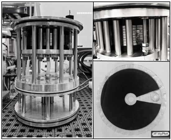
Figure 9.
Assembled hardware (left picture courtesy of Eirini Vlachaki), water leaving the stack during operation (upper right), and MEA after use.
The first test was performed in order to verify that the water was equally fed to all cells in the stack and that all channels received an equal amount of water. This was carried out by visual inspection, feeding a high amount of water directly into the electrolyzer sections, and it was found that the distribution was uniform from cell to cell and channel to channel. Figure 9, upper right, shows the water exiting the anode channels during operation. It was also noticed that the current design does not suffer from the uneven water distribution between the cells as must occur in a design where both inlet and outlet ports are placed on the top.
Then, the assembly was pushed into the vessel. This proved difficult because of the tight fit. The main reason was that we chose three outer sealing rings of the same size. The thickness of the rings was 2 mm, which was dictated by the 5 mm thickness of the plates used. A 2 mm wide ring requires a 2.8 mm high groove, whereas a 3 mm thick ring requires a 4.2 mm high groove, and this leaves an insufficient amount of solid area. In a prototype, thicker plates will be used that can accommodate 3 mm strong o-rings. It will also be designed in such a way that the three larger outer o-rings have different sizes, with the smallest at the bottom, to make the assembly easier. With the current design, it was difficult to assemble, and the lowest o-ring was damaged during the assembly or disassembly. It will most likely be found that the design is dictated by the o-ring sizes that are available. In the current design, the smaller sealing rings for the bipolar plates were kindly provided by Trelleborg Sealing Solutions, while the larger o-rings were purchased from HUG Technology and Security GmbH (www.hug-technik.com).
When the assembled electrolyzer was to be tested on a Greenlight Innovation electrolyzer test bench, more problems were encountered because the test bench is designed such that the multiphase mixture of excess water and oxygen escaping from the anode outlet would be fed inside the test bench into an internal phase separator. This was incompatible with our design, as we used internal phase separation and there would only be a gas and vapor stream leaving the anode outlet.
The operating temperature of this electrolyzer was to be controlled exclusively via the feed water. To this end, thermodynamic calculations were performed to identify suitable feeding rates [42].
While the first performance data were satisfactory (we achieved a current density beyond 1.0 A/cm2 at a cell voltage of around 2 V per cell), it was also found that because of the expansion when the stack heated up, the contact resistances became very large when the stack cooled down again. Hence, in the future, thermal washers or other materials with a negative thermal expansion coefficient must be employed.
Unfortunately, it was found that several membranes had been cut by the edges of the bipolar plates when the stack was heated up and expanded, so that the research project had to be discontinued. However, enough findings were made to justify the building of a prototype, which will be carried out in future work.
5. Cost Considerations
A general problem with PEM electrolyzers is the higher cost compared to alkaline technology [6]. The main reason for the higher capital expenses is the need for precious metals as catalysts and other expensive materials such as titanium for the bipolar plates. This technology can only be cost-competitive if an accordingly higher performance/efficiency is achieved such that the operational expenses are lower compared to other technologies.
A rough cost breakdown of the materials used in the current design is shown in Table 3. These figures apply to a small-scale electrolyzer with 15 single cells leading to an active area of 1036 cm2. To this end, we purchased a Grade 5 titanium plate with dimensions of 500 mm × 500 mm, which could be used to make 14 bipolar plates and 2 monopolar plates. Due to confidentiality, the cost of the MEAs was only roughly estimated, but the supplier suggested that it can be decreased by 30–40%, depending on the amounts ordered. The exact catalyst loading and type were not disclosed. The manufacturing costs were also roughly estimated, and they depend strongly on the local wages and electricity prices. Overall, an optimistic scenario is that this electrolyzer with an area of around 1000 cm2 can be made for EUR 5000 in a first step towards mass manufacturing. Other, potentially expensive, controlling devices such as mass flow controllers are not listed.
Table 3.
Cost breakdown of the proof-of-concept design with a total area of around 1000 cm2.
As the performance can currently only be estimated, two different scenarios are presented. The more pessimistic case sees a current density of 1.0 A/cm2 at a cell voltage of 1.8 V per cell, leading to a power requirement of 1.85 W or a CAPEX of 2700 EUR/kW. In a more optimistic case, we may achieve 2.7 A/cm2 at the same voltage, which yields a total power of 5 kW and a CAPEX of 1000 EUR/kW. When increasing the design by adding more cells, the cost per kW will likely decrease.
It is also noted that when the performance in the above cases is worse such that the cell voltage at a given current density is higher, then the power rating of the stack accordingly increases and the cost per kW decreases, which is a known paradox in electrolyzer ratings. Therefore, the power used per mass of hydrogen produced is more instructive, and the above figures are a mere indication. Ultimately, it is the cost of hydrogen at a desired pressure that should matter, and the desired end pressure depends on the application. If hydrogen is generated to be transported in pipelines, a pressure between 60 and 100 bar is desired, whereas if the hydrogen is to be locally produced, e.g., by a steel maker, then lower pressures are sufficient, and the electrolyzer performance is likely to increase [37].
6. Conclusions
A novel proton exchange membrane electrolyzer design has been presented. Starting from a radially outward channel design for the water, fed by a central hole, the water distribution was very uniform over each plate. Because the outlet pressure at the water side for each plate was the same and the feeding hole can be made large enough to neglect the pressure drop inside, typical problems associated with cylindrical electrolyzers are avoided. The hydrogen flow field is circular, which avoids shear stresses and leads to small areas of unsupported membranes. The sealing can be performed exclusively via o-rings, and the sealing areas are small. The electrolyzer is integrated with a heat exchanger to preheat the incoming water. It also serves as phase separator so that the condensed water can be immediately recirculated, and the gas phase contains mostly oxygen and some water vapor. The entire assembly is housed in a cylinder which can be made out of hard plastic to reduce thermal losses, cost, and weight. The oxygen/water vapor outlet can be connected to a vacuum pump to operate the anode side below ambient pressure with the goal of increased efficiency.
The first tests have shown that the electrolyzer can be easily assembled, but testing on a commercial test bank was challenging, and a dedicated test bench has to be built. It was, however, verified that the water flow rate on the anode side was very uniform. At the cathode side at elevated temperature, only gas-phase hydrogen was observed to leave the stack. In the future, an improved prototype will be built and performance tests reported.
Funding
This work received no external funding. The full publication voucher from MDPI is gratefully acknowledged.
Data Availability Statement
The technical drawings in this article will be made available by the author upon request.
Acknowledgments
The author wants to thank Ali Enkeshafi and Na Li for the help during the assembly phase. The Master’s students Eirini Vlachaki, Konstantinos Lekatsas, Eleni Maria Boutla and Francisco De Campos Gomes Dinis assisted in the assembly and first testing. All parts with the exception of the membrane–electrode assemblies were manufactured by Bjørn Brøndum Jensen at the AAU Energy machine shop. Jan Christiansen from the AAU Energy machine shop and Dr. Dmitri Bessarabov from Hydrogen South Africa-Infrastructure are thanked for helpful discussions.
Conflicts of Interest
The author declares no conflicts of interest.
References
- Liu, B.; Liao, S.; Cheng, C.; Chen, F.; Li, W. Hydropower curtailment in Yunnan Province, southwestern China: Constraint analysis and suggestions. Renew. Energy 2018, 121, 700–711. [Google Scholar] [CrossRef]
- Feng, Q.; Yuan, X.; Liu, G.; Wei, B.; Zhang, Z.; Li, H.; Wang, H. A review of proton exchange membrane water electrolysis on degradation mechanisms and mitigation strategies. J. Power Sources 2017, 366, 33–55. [Google Scholar] [CrossRef]
- Lettenmeier, P.; Wang, R.; Abouatallah, R.M.; Saruhan, B.; Freitag, O.; Gazdzicki, P.; Morawietz, T.; Hiesgen, R.; Gago, A.S.; Friedrich, K.A.; et al. Low-Cost and Durable Bipolar Plates for Proton Exchange Membrane Electrolyzers. Sci. Rep. 2017, 7, 44035. [Google Scholar] [CrossRef] [PubMed]
- Schmidt, O.; Gambhir, A.; Staffell, I.; Hawkes, A.; Nelson, J.; Few, S. Future cost and performance of water electrolysis: An expert elicitation study. Int. J. Hydrogen Energy 2017, 42, 30470–30492. [Google Scholar] [CrossRef]
- Wang, C.R.; Stansberry, J.M.; Mukundan, R.; Chang, H.M.J.; Kulkarni, D.; Park, A.M.; Plymill, A.B.; Firas, N.M.; Liu, C.P.; Lang, J.T.; et al. Proton Exchange Membrane (PEM) Water Electrolysis: Cell-Level Considerations for Gigawatt-Scale Deployment. Chem. Rev. 2025, 125, 1257–1302. [Google Scholar] [CrossRef]
- Taibi, E.; Blanco, H.; Miranda, R.; Carmo, M. Green Hydrogen Cost Reduction: Scaling up Electrolyzers ot Meet the 1.5 °C Climate Goal; Technical report; International Renewable Energy Agency (IRENA): Abu Dhabi, United Arab Emirates, 2020. [Google Scholar]
- Mardle, P.; Chen, B.; Holdcroft, S. Opportunities of Ionomer Development for Anion-Exchange Membrane Water Electrolysis. ACS Energy Lett. 2023, 8, 3330–3342. [Google Scholar] [CrossRef]
- Berning, T.; Bessarabov, D. GOMEA: A Conceptual Design of a Membrane Electrode Assembly for a Proton Exchange Membrane Electrolyzer. Membranes 2023, 13, 614. [Google Scholar] [CrossRef]
- Rasten, E.; Hagen, G.; Tunold, R. Electrocatalysis in water electrolysis with solid polymer electrolyte. Electrochim. Acta 2003, 48, 3945–3952. [Google Scholar] [CrossRef]
- Nuttall, L.; Russell, J. Solid polymer electrolyte water electrolysis—development status. Int. J. Hydrogen Energy 1980, 5, 75–84. [Google Scholar] [CrossRef]
- Stucki, S.; Scherer, G.G.; Schlagowski, S.; Fischer, E. PEM water electrolysers: Evidence for membrane failure in 100kW demonstration plants. J. Appl. Electrochem. 1998, 28, 1041–1049. [Google Scholar] [CrossRef]
- Marshall, A.; Børresen, B.; Hagen, G.; Tsypkin, M.; Tunold, R. Hydrogen production by advanced proton exchange membrane (PEM) water electrolysers—Reduced energy consumption by improved electrocatalysis. Energy 2007, 32, 431–436. [Google Scholar] [CrossRef]
- Siemens Energy. Green Hydrogen Production. 2025. Available online: https://www.siemens-energy.com/global/en/home/products-services/product-offerings/hydrogen-solutions.html (accessed on 25 April 2025).
- NEL. PEM Electrolyser—S Series. 2025. Available online: https://nelhydrogen.com/product/s-series-electrolyser/ (accessed on 25 April 2025).
- NEL. PEM Electrolyser—MC Series. 2025. Available online: https://nelhydrogen.com/product/mc-series-electrolyser/ (accessed on 25 April 2025).
- Bosch. Hybrion PEM Electrolysis Stacks. 2025. Available online: https://www.bosch-hydrogen-energy.com/pem-electrolysis/pem-elektrolysis-stacks/ (accessed on 25 April 2025).
- Plug Power. Plug EX-2125D Electrolyzer. 2025. Available online: https://resources.plugpower.com/electrolyzer-hydrogen-production/ex-2125d-f041122 (accessed on 25 April 2025).
- Plug Power. Plug EX-4250D Electrolyzer. 2025. Available online: https://resources.plugpower.com/electrolyzer-hydrogen-production/ex-4250d-f041122 (accessed on 25 April 2025).
- Cummins. HyLYZER Water Electrolyzers. 2025. Available online: https://mart.cummins.com/imagelibrary/data/assetfiles/0070328.pdf (accessed on 25 April 2025).
- ITM. Neptune V. 2025. Available online: https://itm-power-assets.s3.eu-west-2.amazonaws.com/Neptune_V_Spec_Sheet_2_7_8002544a71.pdf (accessed on 25 April 2025).
- Thomassen, M.S.; Barnett, A.O. Polymer Electrolyte Membrane (PEM) Water Electrolyser Cell, Stack and System and a Method for Producing Hydrogen in Said PEM Water Electrolyser System. Norwegian Patent NO343985B1, 5 August 2019. [Google Scholar]
- HySTAR. Hystar’s PEM Electrolyzer Technology. 2025. Available online: https://landing.hystar.com/hystar-brochure (accessed on 25 April 2025).
- Haryu, E.; Kawasaki, N.; Ishikawa, H. Differential Pressure Water Electrolysis System. U.S. Patent 10,053,783 B2, 21 August 2018. [Google Scholar]
- Kosek, J.A.; Giner, B.; LaConti, A.B. Method and System for Producing High-Pressure Hydrogen. U.S. Patent 8,282,811 B2, 9 October 2012. [Google Scholar]
- Baschuk, J.J.; Li, X. Modelling of polymer electrolyte membrane fuel cell stacks based on a hydraulic network approach. Int. J. Energy Res. 2004, 28, 697–724. [Google Scholar] [CrossRef]
- Millet, P.; Ngameni, R.; Grigoriev, S.; Fateev, V. Scientific and engineering issues related to PEM technology: Water electrolysers, fuel cells and unitized regenerative systems. Int. J. Hydrogen Energy 2011, 36, 4156–4163. [Google Scholar] [CrossRef]
- Grigoriev, S.; Porembskiy, V.; Korobtsev, S.; Fateev, V.; Auprêtre, F.; Millet, P. High-pressure PEM water electrolysis and corresponding safety issues. Int. J. Hydrogen Energy 2011, 36, 2721–2728. [Google Scholar] [CrossRef]
- Olesen, A.C.; Rømer, C.; Kær, S.K. A numerical study of the gas-liquid, two-phase flow maldistribution in the anode of a high pressure PEM water electrolysis cell. Int. J. Hydrogen Energy 2016, 41, 52–68. [Google Scholar] [CrossRef]
- Olesen, A.C.; Frensch, S.H.; Kær, S.K. Towards uniformly distributed heat, mass and charge: A flow field design study for high pressure and high current density operation of PEM electrolysis cells. Electrochim. Acta 2019, 293, 476–495. [Google Scholar] [CrossRef]
- Ito, H.; Maeda, T.; Nakano, A.; Hasegawa, Y.; Yokoi, N.; Hwang, C.; Ishida, M.; Kato, A.; Yoshida, T. Effect of flow regime of circulating water on a proton exchange membrane electrolyzer. Int. J. Hydrogen Energy 2010, 35, 9550–9560. [Google Scholar] [CrossRef]
- Hancke, R.; Bujlo, P.; Holm, T.; Ulleberg, Ø. High-pressure PEM water electrolyser performance up to 180 bar differential pressure. J. Power Sources 2024, 601, 234271. [Google Scholar] [CrossRef]
- Kopp, M.; Coleman, D.; Stiller, C.; Scheffer, K.; Aichinger, J.; Scheppat, B. Energiepark Mainz: Technical and economic analysis of the worldwide largest Power-to-Gas plant with PEM electrolysis. Int. J. Hydrogen Energy 2017, 42, 13311–13320. [Google Scholar] [CrossRef]
- Flamm, B.; Peter, C.; Büchi, F.N.; Lygeros, J. Electrolyzer modeling and real-time control for optimized production of hydrogen gas. Appl. Energy 2021, 281, 116031. [Google Scholar] [CrossRef]
- Selamet, Ö.F.; Becerikli, F.; Mat, M.D.; Kaplan, Y. Development and testing of a highly efficient proton exchange membrane (PEM) electrolyzer stack. Int. J. Hydrogen Energy 2011, 36, 11480–11487. [Google Scholar] [CrossRef]
- Briguglio, N.; Brunaccini, G.; Siracusano, S.; Randazzo, N.; Dispenza, G.; Ferraro, M.; Ornelas, R.; Aricò, A.; Antonucci, V. Design and testing of a compact PEM electrolyzer system. Int. J. Hydrogen Energy 2013, 38, 11519–11529. [Google Scholar] [CrossRef]
- Wirkert, F.; Roth, J.; Jagalski, S.; Neuhaus, P.; Rost, U.; Brodmann, M. A modular design approach for PEM electrolyser systems with homogeneous operation conditions and highly efficient heat management. Int. J. Hydrogen Energy 2020, 45, 1226–1235. [Google Scholar] [CrossRef]
- Hancke, R.; Holm, T.; Ulleberg, Ø. The case for high-pressure PEM water electrolysis. Energy Convers. Manag. 2022, 261, 115642. [Google Scholar] [CrossRef]
- Nguyen, T.V. A Gas Distributor Design for Proton-Exchange-Membrane Fuel Cells. J. Electrochem. Soc. 1996, 143, L103. [Google Scholar] [CrossRef]
- Berning, T.; Odgaard, M.; Kær, S.K. A study of multi-phase flow through the cathode side of an interdigitated flow field using a multi-fluid model. J. Power Sources 2010, 195, 4842–4852. [Google Scholar] [CrossRef]
- Alloys, A. Negative Thermal Expansion Washers. 2025. Available online: https://allvaralloys.com/negative-coefficient-of-thermal-expansion-products-applications/negative-cte-washers/ (accessed on 28 January 2025).
- Weber, C.C.; Wrubel, J.A.; Gubler, L.; Bender, G.; De Angelis, S.; Büchi, F.N. How the Porous Transport Layer Interface Affects Catalyst Utilization and Performance in Polymer Electrolyte Water Electrolysis. ACS Appl. Mater. Interfaces 2023, 15, 34750–34763. [Google Scholar] [CrossRef]
- Vlachaki, E.; Lekatsas, K.; Berning, T. A Thermodynamic Analysis of a Proton Exchange Membrane Electrolyzer. ECS Trans. 2024, 114, 595. [Google Scholar] [CrossRef]
Disclaimer/Publisher’s Note: The statements, opinions and data contained in all publications are solely those of the individual author(s) and contributor(s) and not of MDPI and/or the editor(s). MDPI and/or the editor(s) disclaim responsibility for any injury to people or property resulting from any ideas, methods, instructions or products referred to in the content. |
© 2025 by the author. Licensee MDPI, Basel, Switzerland. This article is an open access article distributed under the terms and conditions of the Creative Commons Attribution (CC BY) license (https://creativecommons.org/licenses/by/4.0/).