1. Introduction
The search for energy alternatives to reduce human dependency on fossil fuels has been a very pressing topic for the last few decades. Rapidly, dihydrogen emerged as a carbon-free fuel with the highest known energy content, while emitting in its combustion, in a fuel cell or combustion chamber, only water as by-product. Dihydrogen, often called hydrogen, is the smallest homo diatomic gas with a molar mass of 2 g·mol−1 and a density at room temperature and pressure of 0.08 kg·m−3. Hydrogen is an odorless, colorless, tasteless and non-toxic gas in standard pressure and temperature conditions. Hydrogen is the most abundant atom in the universe, it represent 92 at.-% of the visible universe, but on Earth atmosphere it represent only 0.22 at.-% and about 1 at.% on Earth’s crust. As hydrogen is not a primary resource on earth, it means that it needs to be extracted from hydrogen rich feed-stock such as water H2O or hydrocarbons CxHy. It is called green, when it is produced from water splitting using renewable electricity (electrolysis) or solar energy (photoelectrolysis) while it is named grey, when it is generated from steam methane reforming on natural gas without carbon capture.
So, a closed cycle is expected to form the basis of a future CO
2-free energy system when green hydrogen is as a fuel or more generally as an energy vector. Indeed, the combustion reaction of hydrogen with oxygen is an exothermic reaction. At standard temperature and pressure conditions, the Higher Heating Value is 141.8 MJ·kg
−1 [
1]. The only product resulting from the reaction is water.
In the same time, dihydrogen flammability limit ranks from 4 up to 75 vol% in air with a minimal ignition energy of 0.2 mJ, which makes it an easily flammable gas in atmospheric conditions. As a consequence, its storage requires not only a high storage capacity but also good and safety operability. Dihydrogen storage is still technologically challenging. There are mainly 5 storage technologies, compressed gas, liquid in cryogenic tanks, sluches, chemicals and solids. Unfortunately, all these high-density hydrogen storage media operate under particular conditions. For example, for gas storage, mechanically and chemically resistant pressure vessels are required. For liquid storage a robust cryogenic setup operating at 20 K is mandatory. Binding hydrogen atoms in chemicals, like ammonia or formic acid, requires fueling infrastructure that can withstand the corrosive nature of these molecules. Dihydrogen physisorption on porous solids, like metal–organic frameworks (MOFs) requires an adsorption of H2 molecules at relatively low temperatures, typically the temperature of liquid nitrogen, which is somewhat costly. Regarding dihydrogen chemisorption on complex or simple metal hydrides, in which atomic hydrogen is covalently bonded to the hosting crystal lattices, the exothermic character of the hydride formation reaction induces a heat release upon uptake of each mole of hydrogen. This heat must be removed during charging; otherwise, equilibrium temperature would be reached quickly and the reaction would stop. Conversely, to achieve a fast hydrogen release, it is necessary to supply the heat of the reaction, the desorption being an endothermic reaction. So, an efficient thermal management has to be achieved, through for instance improving the thermal conductivity of the involved hydrides.
Focusing on car transportation, technically and economically viable storage solutions have to be implemented for the development of hydrogen vehicles. Indeed, fossil fuel-based car transportation contributes significantly in green-house gas emission and consequently to climate change. The replacement of such vehicles by hydrogen driven ones, including passenger cars and buses, which are powered by electricity while producing only water vapor as a tailpipe emission, is an interesting scenario to face the next energy needs and transportation depollution challenges. Hydrogen in transport is still in its infancy. Despite a continuous increase in hydrogen consumption, hydrogen represents no more than 0.003% of transport energy consumption worldwide in the twenty twenties [
2]. Pioneer’s hydrogen cars have been started to be commercialized but they still haven’t completely penetrated the automotive market. Since 2015, three hydrogen-powered cars have been offered for sale from three different car companies: the HONDA Clarity (
https://hondanews.com/en-US/honda-automobiles/channels/honda-clarity-fuel-cell, accessed on 15 October 2023), the HYUNDAI Nexo (
https://www.hyundai.com/fr/fr/modeles/nexo.html, accessed 15 October 2023) and the TOYOTA Mirai (
https://www.toyota.fr/vehicules-neufs/mirai, accessed on 15 October 2023). HONDA has now ended production of all models of the Clarity, and HYUNDAI has sold fewer than thousands of Nexo cars over the words. As a point of reference, TOYOTA is nowadays the most devoted company to hydrogen powder as an alternative to battery-electric vehicles, even if it has resorted to substantial discounts to sell its hydrogen-driven cars. HONDA does not break out sales of its Clarity Fuel Cell model from the plug-in-hybrid and battery-electric Clarity versions.
In all these hydrogen-driven vehicles, energy is stored in the form of compressed hydrogen fuel, rather than in a battery. The hydrogen fuel-cells convert compressed hydrogen from their fuel tanks into electricity that powers the electric motor in the vehicle, providing a similar range to vehicles powered by internal combustion engines using gasoline or diesel. The chemical reaction between hydrogen and oxygen in the fuel cell stack to provide electricity, is nowadays thanks to the dihydrogen gas transported in compressed vessel in the vehicles. By this way, dihydrogen-powered cars can cover long distances, and only take a few minutes to refuel if the automotive engineering challenges are overcome.
The first challenge is related to the dihydrogen fuel cells themselves, which are happiest at a steady power output. That’s what makes them suitable for backup power use, but the power demands in the average car vary by an order of magnitude, from something like 15 kW (20 horsepower—hp) to keep a vehicle at a steady highway speed on a flat road to perhaps 10 or 20 time more for maximum acceleration to 96 km per hour or higher. The fuel cell in the Toyota Mirai, the best-selling hydrogen car, is rated at 90 kW (120 hp). But that’s not enough to accelerate onto a fast-moving highway, so Toyota adds in a high-voltage low-capacity battery, very similar to those used in gasoline-electric hybrid vehicles. It’s there to supply supplemental power for short periods of intense acceleration, and it’s recharged from either excess fuel-cell output when the car is cruising at a steady speed or via regenerative braking when the car slows.
The second challenge is about the safety of the high-pressure tanks embedded in the hydrogen cars. These tanks are assumed to be mechanically resistant able to survive even the highest-speed crashes without leaking or breaching. While hydrogen skeptics routinely cite the Hindenburg explosion of 1937, the hydrogen tanks and their hardware should be designed to likely survive even if the rest of the car were destroyed in a crash. To date, no injuries or deaths specific to the hydrogen components have been recorded in the relatively small number of hydrogen-driven sold cars. But the point of their breaking risks remains still questionable.
The third challenge is about the ability of governments to install large hydrogen gas refueling stations, online and available for fueling at all times. Today, many hydrogen drivers rely on that app to map their fueling stops before they venture out. Besides, most of the available stations can often only fuel 2 to 12 vehicles before they go offline for up to half an hour to repressurize. This has to be contrasted with gasoline cars, for which there’s a well-developed set of more than tens to hundreds of thousands fuel stations per developed country. Dihydrogen drivers are utterly dependent on both a reliable supply of the gas itself and an available—and properly operating—high-pressure fueling station.
Researches are in progress, to introduce metal hydrides as alternative hydrogen storage approach, to solve at least a part of the pointed out challenges, through in particular the use of fine metal hydride powder and adapted heat exchangers. The heat exchangers are critical because metal hydrides stop absorbing hydrogen effectively if they overheat. Within optimized metal hydride, contained in compartments inside the storage pressure vessel, and ingenious heat exchangers, the gas storage tank can be filled quickly, while accessory connectors supply coolant to extract the heat. By such a system, motorists would be able to fill their car with hydrogen within a few minutes. The hydrogen would then be used to power the fuel cell to generate electricity to drive the electric motor. In this scenario, gas dihydrogen refueling stations would be no longer required. A new refueling model would be developed based on returnable hydride cassettes. Charged hydride-based cartridges could be stored in classical gasoline city stations. These cartridges could be purchased by hydrogen car drivers, exchanging by themselves the discharged ones by charged ones. Of course, the viability of such economic model has to be seriously evaluated in relation to the technical possibilities offered by hydride material processing and its global energy cost.
In this general context, this tutorial review provides an overview of the different types of hydrogen storage with a focus on solid storage processing. It also describes the last technical achievements on hydrogen driven car transportation, explaining how they operate and how hydrogen is stored in. Lastly, some challenges and future outlooks pertinent to underground hydrogen storage in cars are exposed. This article will serve as a useful resource that provides a quick overview of underground hydrogen storage for both scientist and engineer trainees. Despite a huge amount of reviews on hydrogen combustion, hydrogen production and/or hydrogen fuel vector. those on hydrogen-based ground transportation are very scarce.
2. Hydrogen, from the Unknown to the Breakthrough Discoveries
2.1. Hydrogen Discovery
Hydrogen discovery is an interesting story since it reflects the evolution of knowledge over time. P. T. A. Bombast von Hohenheim around 1520 was the first scientist who observed dihydrogen by dissolving metals such as iron, zinc and tin into sulfuric acid. His early experiments led to the actual discovery of hydrogen as a homo-diatomic gas. Hydrogen was then reported as a “flammable solution of iron” by R. Boyle in 1671. He mixed metallic iron and sulfuric acid, which lead to the production of gaseous hydrogen and iron sulfate.
Almost a century later, H. Cavendish produced the gas over mercury and described it as “an inflammable air from metal”. He suggested that the gas was released from the metal rather than the acid. And he isolated it as a single substance, but he mischaracterized it as a substance related to “phlogiston”. Finally, A. Lavoisier in 1783 gave the current hydrogen name from the Greek meaning “water-former” distinguishing hydrogen as a single substance whom combustion with O2 leads to the formation of water.
2.2. Hydrogen in the History
Historically, hydrogen was produced by the mixture of a strong acid with a selected metal. But in 1780, F. Fontana discovered the water-gas shift reaction which consists of producing CO2 and H2 gas by reacting carbon monoxide with steam, and in 1873 T. S. C. Lowe first produced water gas (H2 + CO) as a fuel from this process. Then A. Frank, C. von Linde and H. Caro developed an innovative technique in 1909 to separate H2 and CO2 from water gas: the Linde-Frank-Caro process. In 1784, A. Lavoisier and J.-B. M. Meusnier developed the Lavoisier-Meusnier iron-steam process to produce hydrogen. It is water splitting at high temperature: water vapor is passing over a red hot iron plate (600 °C). Then in 1789, J. R. Deiman and A. P. Ven Troostwijk performed the first electrolysis of water with an electrostatic machine combined with a Leyden jar. In 1799, A. Volta published his experiments about the voltaic pile, a device able to provide continuous electric current. The creation of this device was a breakthrough and led to a more efficient method to perform water splitting by W. Nicholson and A. Carlisle in 1800.
Water splitting was even more efficient thanks to J. Wilhelm Ritter who built the same year a set up to separate dihydrogen from dioxygen.
Hydrogen can also be produced from the bio-activity of algae. In 1896, D. D. Jackson and J. W. Ellms discovered that Anabaena microalgae was able to spontaneously produce hydrogen. And in 1939, H. Gaffron studied the mechanism and biochemistry of photosynthesis and discovered that unicellular green algae can switch from the production of O2 to H2 in the presence of light.
Focusing on transportation applications, Hydrogen was widely used throughout history. Everything started in 1783, when J. Charle made the first flight with a hydrogen balloon named “la Charlière”. It is the first occurrence in history of the use of hydrogen for transportation, hydrogen being used as a lifting agent, starting thus the “balloonmania”. Among the most famous hydrogen fueled vehicles, the Zeppelin Airship success story remains the most impressive but yet tragic. Count F. von Zeppelin, designed and launched the first successful rigid airship lifted by H2 in 1900, the Zeppelin LZ1. In 1909, the LZ5 made the first long distance flight, a year later the LZ13 was the first flight with passengers. In 1929, the LZ127 made the last circumnavigation of the world, it traveled about 33,234 km in 21 days, 5 h and 31 min. The Zeppelin monopoly brutally stopped in 1937 with the LZ129, the last airship built by the company. It caught fire in the air. The explosion was assumed to be due to a static electricity from the balloon that caused a fire inside the gas chamber. This accident shocked and highlighted the danger around the use of hydrogen for any purpose.
Hydrogen was also tested for combustion engines. The history of combustion engines working with dihydrogen and dioxygen, started in 1806 with F. I. De Rivaz and then in 1826 with S. Brown who tested for the first time the hydrogen fueled internal combustion engine to propel a vehicle in the South East of London. R. Erren then patented in 1930 the hydrogen and oxygen (gaseous) fueled internal combustion engine.
Finally, the development of the fuel cell enables to broaden the use of hydrogen. In 1801, H. Davy published on the concept of a fuel cell to convert the potential chemical energy stored in hydrogen into electricity. It was followed in 1836 by the invention of the first primary cell converting gaseous hydrogen into electricity. It was only in 1839 that C. F. SchonbeinCHONBEIN published the principle of the fuel cell. Then in 1839, W. R. GROVE developed the grove cell, a primary cell that led in 1842 to the development of the first fuel cell. In 1889, L. Mond and C. Langer coined the name fuel cell and developed a device working on air and mond gas. F. W. Ostwald was the first to theorize the roles of each component of the fuel cell. Hydrogen powdered fuel cells were then naturally considered for automotive transportation and the first modern fuel cell vehicle was proposed in 1959. It was a modified Allis-Chalmers farm tractor, fitted with a 15 kilowatt fuel cell. in 1966, General Motors developed the first fuel cell road vehicle, the Chevrolet Electrovan.
2.3. Hydrogen Today
Worldwide Hydrogen demand is regularly reported by the International Energy Agency (IEA). It reached more than 90 MT in 2022 and it is expected to grow due to population growth and industry development. As a point of reference, in Europe, hydrogen consumption in all sectors was about 8.6 Mt in 2022, which represents 76% of the European hydrogen production (11.4 Mt).
Hydrogen is used in different activity sectors (
Table 1). Among them, the most hydrogen consuming is the petroleum refining (~57% in 2022), particularly for hydrocking (39.8 Mt in 2022), ammonia and methanol production (~38% in 2022) and metallurgy processes (~2% in 2022). A very small part of the whole produced hydrogen is nowadays reserved for hydrogen-fueled car transportation. In such cars, hydrogen acts as a fuel for embedded fuel cells providing electricity to the electric engine and the battery for further use. Even if the hydrogen fuel cell technology is becoming more and more mature, those vehicles represent a small fraction in the operating vehicles. This is mainly due to the lack of fueling stations, making such a market still emerging. Hydrogen fueling stations map is evidenced on H2stations website (
https://www.h2stations.org, accessed 15 October 2023). When displaying the available fueling stations worldwide, we can distinguish four main regions with no more than some tens of units: (1) North America with California as a leader, (2) Europe, (3) China, Japan and South Korea and (4) Australia and New Zealand. In France there is around 40 operating fueling stations. This number is far behind the number of fossil fuel stations, which accounts for around 11,000 in France, underlying the necessity to develop hydrogen fueling stations and embedded solid storage facilities.
3. Hydrogen as an Energy Vector toward Energy Challenges
3.1. Energy and Ecological Situation
The industrial revolution around 1800 led the way of tremendous production of various goods, the intensive exploitation of natural resources and the excessive pollution of environments (air, see, land), initiating climate change.
Today, the jeopardized wildlife (flora and fauna) by the pollution, the over-consumption of fossil resources in a word economy almost exclusively built on fossil energy, the continuously growing carbon dioxide CO
2 emissions (
Figure 1), that can lead to agricultural and health issues, are now relentless. As CO
2 emissions are continuously rising [
4] and atmospheric carbon capture unreachable, global warming seems inexorable. We cannot escape our fate. Air pollution is the third cause of death worldwide after high blood pressure and smoking, which are related to unhealthy lifestyle that can easily be solved compared to the struggle to find solution for a carbon-free energy transition. CO
2 is a green-house gas. Green houses gases are gases able to absorb and emit radiant energy in the thermal infrared range, it means that those gases have the ability to absorb and emit radiant energy from the Sun to heat up Earth. The highest the concentration of those gases in the atmosphere and the stronger is the phenomenon leading to a global warming. The consequences are as destructive to the environment as they are to human lives. Among the biggest effects of global warming on our planet we can quote the melting of glaciers that causes rising of sea level leading to endangered sea-cost and reduction of land surface. According to the Intergovernmental Panel on Climate Change (IPCC), also known as
Groupe d’Experts Intergouvernemental sur l’Évolution du Climat (GIEC) for French speakers, various strategies and perspectives had been considered to reduce global warming at a few degrees. Among all the propositions, the key point is reducing our global CO
2 emissions drastically and durably.
Among the most polluting sector, road transportation accounts for 11.9% worldwide. Fossil fuel use for road transportation is the leading cause of CO
2 emissions. in Europe accounting for about 61% of total emissions. Fossil fuel are divided in three categories: oil, coal and gas which constitutes the main part of the global primary energy consumption sources [
5] (
Figure 2). In the same time, oil and natural gas stocks are depleting and would be soon replaced be face the worldwide increasing energy demands, including for domestic ground transportation. So it became crucial to reduce the use of carbon-based fuels and turning to green or low-carbon energy vectors, developing carbon capture in all industries, improving energy efficiency and replacing fossil fuel terrestrial vehicle by electrical or hydrogen driven ones. The challenge toward fossil fuel is not only about climate it is also about reserves left. Depletion times for oil, coal and gas are estimated of approximately 35, 107 and 37 years, respectively. This means that coal reserves are available up to 2112, and will be the only fossil fuel remaining after 2042 [
6].
3.2. Energy Mix
Energy is a critical problem in today’s society among clean water access, food sustainable production and environment. But yet definitions of the word energy are vague and ambiguous. Cambridge dictionary defines it as the “power to do work that produces light, heat, or motion, or the fuel or electricity used for power”. In fact, it defines the consequences of energy on mater rather than its spirit. In physics, it is described as the ability to do work with the equation:
with P is the average power output, measured in watts (W), ΔE
sys is the net change in energy of the considered system in joules (J), also known as work and Δt is the duration, namely how long the energy use takes—measured in seconds (s). So, extracting energy is removing it from its initial environment to transform it in useful energy with a converter. In other words, primary energy is the source and energy vector is the useful energy.
Primary energy can be classified in three categories: renewable, fossil and nuclear. Renewable energy is energy taken from natural sources that are replenished at a higher rate than they are consumed. The French Institut National de la Statistique et des Etudes Economiques (INSEE) describes green energy sources as “solar (photovoltaic or thermal), wind (wind turbine), river and ocean water (hydraulic, tidal, etc.), biomass, whether solid (wood and biowaste), liquid (biofuels) or gaseous (biogas), as well as heat from the earth (geothermal) and heat extracted by heat pumps”.
Fossil fuel is energy taken from Earth crust by mining solid, liquid or gaseous hydrocarbons. Since this matter comes from dead carbon-rich organisms buried million years ago, this energy source is not renewable. In today’s energy mix, fossil fuel represents 84.3% of primary energy consumed in the word, while renewable only account for 11.4% (
Figure 2). Fossil fuel combustion is a leading cause of CO
2 emissions, accounting for about 93.57% of CO
2 emissions (34.74 billion tones in 2022 according to
Figure 1.
Transportation of goods and people account for almost a third part of the energy consumed in the word. It is accounts for 28% in France (according to the French Ministère de la Transition Ecologique) and US (according to the US Energy Information Administration) among whom 91% from petroleum-based fuel in both countries. Even if the use of bio-fuel, natural gas and electricity is rising, the change is not significant enough to be noted. Among the solution considered in the transportation field, the use of hydrogen as an energy vector seems promising.
3.3. Hydrogen as an Energy Vector
The Hydrogen Economy describes an energy model based on the use of hydrogen as a green and renewable energy vector. Yet, its aim is to replace fossil fuel economy particularly for goods and people transportation. Hydrogen has a specific energy 3 times higher than conventional fuels such as diesel or gasoline, 5 times higher than synthetic fuel such as ethanol and 10 times higher than natural fuel such as wood. But in terms of energy density, gaseous hydrogen in standard pressure and temperature conditions is low (0.01188 MJ·L−1). When compressed at 690 bar at 15 °C hydrogen energy density rises at 5.323 MJ·L−1 but remains lower than both diesel and gasoline which can hold 38.6 MJ·L−1 and 34.2 MJ·L−1 respectively.
Hydrogen can easily be converted into electricity by either electrochemistry (in a fuel cell) or into mechanical energy and heat by combustion (in internal combustion engine) with gaseous water as only by product. However, hydrogen is a hazardous gas due to its high flammability properties. Its flammability limit range is wider than conventional fuels such as gasoline: 4 to 75 vol.-% for hydrogen and 1.4 to 7.4 vol.-% for gasoline in air. Its minimum ignition energy is 0.02 mJ while for conventional explosive such as TNT whom minimum energy is 3750 higher. It means that hydrogen is more easily ignited than most of other chemicals. Hydrogen mass diffusivity in air 0.61 cm2.s−1 is also 4 times faster than CH4, CO2 or even Ar. It means that in case of hydrogen leak (fracture of the gas holder), in an outside environment hydrogen diffuse rapidly and empty the container which lead to nothing dangerous except if an ignition source blazes the hydrogen/air mixture. This detrimental feature makes hydrogen storage a real challenge in terms of safety and storage efficiency.
Although dihydrogen appears as a good candidate as green energy vector it still faces a few technological obstacles against its broadening. The key technologies to develop are hydrogen production, storage and use. To enable secure and lasting hydrogen economy, those technologies must be affordable, safe according to hydrogen flammability properties and reliable. Even though dihydrogen production had been historically performed by dissolving a selected metal in acid, this technique is not industrially applied. Industrial dihydrogen production methods rely on the use of hydrogen-rich materials such as hydrocarbons, biomass and water. In 2020, hydrogen worldwide production represented 94 million tons which produced more than 900 Mt of CO
2 [
4] (
Figure 3).
96% of today’s hydrogen production comes from fossil resources (47% from natural gas, 27% from coal and 22% from oil) and only 4% from water electrolysis. So, since hydrogen can be produced from various feed-stocks, extraction processes and energy sources, it had recently been fancied to describe hydrogen with colors to separate carbon-free and not renewable hydrogen production. Definitions and categories may change from different sources but here we will agree on:
Green: Electrolysis of water from renewable electricity
Blue: Steam reduction of natural gas with carbon capture
Turquoise: Thermal process on natural gas with renewable energy and carbon capture
Black: Gasification of coal that leads to CO2 emissions
Brown: Gasification of lignite (brown coal) with pollutant emissions
Grey: Steam methane reforming on natural gas and methane without carbon capture
Pink: Electrolysis of water with nuclear energy
Purple-Red: Nuclear produced
Orange: Reaction of water with subsoil ferrous-based rocks
The goal today is to develop the production of carbon-free hydrogen to enable the hydrogen economy to be sustainable, particularly for car transportation application.
To reach industrial production, the challenge is to have a safe, reliable, affordable and efficient green hydrogen production device. It means: (1) producing enough green-energy to sustain the demand, (2) building user-friendly and robust devices to perform water electrolysis and (3) develop safe and reliable hydrogen storage equipment.
Even if water splitting (green hydrogen production) is going to become an industrial reality [
7,
8], hydrogen storage remains technologically challenging. As hydrogen at room temperature is highly flammable it raises safety concerns about hydrogen storage and use. Another point is the very small size of dihydrogen molecule (the H-H bond is 74.14 pm), dihydrogen can escape through materials by permeation but also damage it (hydrogen embrittlement).
4. Hydrogen Storage
The hydrogen storage technology is a multidisciplinary research and development field. It combines material chemistry, engineering, metallurgy, thermodynamic and organochemistry. Nowadays, hydrogen can be stored in different states:
Gaseous: Compressed from 70 up to 700 bar
Liquid: Cryogenic storage at 20 K
SLUSH: A high density mixture of solid and liquid hydrogen
In chemicals: By covalent bonding
Solid: Chemical sorption
Solid: Physical sorption
In the following classification, the key parameters of all these storage technologies are discussed, within the scope of the interaction between the matrix and hydrogen. But, before addressing this topic in details, the six basic hydrogen storage methods and phenomena and their related characteristic properties, namely the gravimetric density ρ
m, the volumetric density ρ
v, the working temperature T and pressure P are listed hereafter (
Table 2).
4.1. High Pressure Gaseous Storage
This technology is the easiest and most widespread hydrogen storage technique, but since hydrogen volumetric density is low, the compression and the volume of the storing tank needs to be high. For this technology, hydrogen is compressed in storage vessels. In practice it only requires three elements: (1) a hydrogen source, (2) a storing cylinder and (3) a compressor. There is currently five generation of compressed hydrogen vessel [
10]:
TYPE I: all metal cylinder;
TYPE II: load-bearing metal liner hoop wrapped with resin-impregnated continuous filament;
TYPE III: non-load-bearing metal liner axial and hoop wrapped with resin-impregnated continuous filament;
TYPE IV: non-load-bearing non-metal liner axial and hoop wrapped with resin-impregnated continuous filament;
Type I cylinder is the first generation of compressed gas storage technology. It is made from either aluminum (MAl = 26.98 g·mol−1) or steel (MFe = 55.85 g·mol−1) and can hold up to 200 bar of hydrogen gas. This technology remains cumbersome, heavy and has the lowest hydrogen energy content. It is mainly used for stationary hydrogen storage such as in industry for large scale use.
Type II cylinder is more sophisticated since it includes a glass fiber with aromatic polyamide or carbon fiber lining around the metal cylinder that can hold around 250 up to 300 bar. About 30-40% lighter than type I, it is about 50% more expensive than type I and still remains cumbersome, heavy and unsuitable for mobile applications [
11].
Type III cylinder is made from composite material such as glass fiber with aromatic polyamide or carbon fiber lined with metal. They can hold 300 up to 440 bar. Its weight half less than type II but is twice as expensive to produce and fails to pass the ageing test at 70 MPa.
Type IV cylinder is made from composite materials such as carbon fiber with a polymer liner such as polyethylene or polyamide thermoplastic. Yet this technology is the lightest developed that can withstand the highest pressure. But it is also the most expensive solution [
11].
Type V hydrogen vessel is from another technology. It is an experimental generation of cylinder composed of a full composite tanks liner-less. This technology requires further research to be safe enough to be used.
From a practical point of view, Hydrogen storage vessels are used for three purposes: (1) stationary storage for refueling station or industrial use, the target properties are large scale and low cost storage, (2) vehicular application for trains, cars, airship and boats, storage device needs to be light and energy dense and (3) bulk transportation from hydrogen producer to end user, to lower the cost of transportation the main requirements are light weight and large capacity [
12].
The main challenge for compressed hydrogen storage is safety. Because a high energy capacity is nothing if it cannot be used properly without causing an explosion. The main phenomenon reducing hydrogen vessel longevity is hydrogen embrittlement. In metal, this phenomenon is due to the absorption of hydrogen that leads to the reduction of the metal ductility. Ductility is the ability to handle deformation without fracture for a metal.
The ISO 15869:2009 norm specifies the requirements for lightweight refillable fuel cylinders intended for the on-board storage of high-pressure compressed gaseous hydrogen or hydrogen blends on land vehicles.
Hydrogen vessels needs to pass various tests such as burst test, leak test, fatigue test bonfire test and the bullet test. The burst test consists of testing the bursting pressure of the vessel. It should be 2 times above the actual working pressure. The permeation test consists of measuring the molecular diffusion of hydrogen through the walls or interstices of the gas vessel over time. The lower the permeation, the better is the storage device. The fatigue test measures the mechanical damage created over cycling of charging/release of hydrogen in the vessel. And the bullet test consists of shooting bullets at the loaded vessel to determine the safety of the device in the case of a shooting by a crazy American.
4.2. Liquid Storage
Liquid hydrogen storage is performed at 20 K in cryo-compressed storage vessel [
13]. The main advantage is the higher energy density compared to conventional compressed hydrogen storage technique. The amount of energy required to cool down to 20 K gaseous hydrogen represents 30% of the lower heating value of hydrogen (120.04 MJ·kg
−1), while for compression it represents only 15% (119.96 MJ·kg
−1).
For long term liquid hydrogen storage two detrimental phenomenon are to take into account: (1) boil off, due to heat transfer between cryo-compressed hydrogen and the environment and (2) evaporation due to hydrogen permeation through the vessel which can represent 2 to 3% of loss per day of storage.
Usually, the vessel is surrounded by an insulation vest to lower heat transfer but increase the weight of the storing device.
4.3. SLUSH Storage
SLUSH hydrogen is a mixture of solid and liquid hydrogen around triple point (between −259 °C and −253 °C). It is obtained through pressure decrease/cooling cycling around hydrogen boiling point. In practice, the fluid follows the mechanism: (1) Liquid hydrogen is heated up near its boiling point, (2) pressure is decreased with a vacuum pump, liquid hydrogen becomes gaseous, decreasing liquid hydrogen temperature, at the gas/liquid interface there is the formation of solid hydrogen due to temperature decrease (3) pressure is then increased and solid hydrogen partially melt and sink leaving the surface free. The process is repeated to increase the liquid solid ratio. Hydrogen slush main feature is its higher density (16–20% higher than liquid hydrogen).
4.4. Storage in Chemicals
The hydrogen atom electronegativity is 2.1 according to Pauling scale. In the science of atomic bonding, the electronegativity is a key parameter to determine the nature of the bonding between two atoms. Hydrogen atoms can be combined to various elements by chemical bonding, the nature and strength of the bonding is related to the electronegativity difference and number of electrons shared in the interaction/relationship (hydrogen atomic number is 1, meaning that it can share 1 electron). Thus, hydrogen atoms can be covalently bonded in chemicals such as ammonia (NH3), formic acid (HCOOH), methanol (CH3OH), methane (CH4) or any Liquid Organic Hydrogen Carrier (LOHC) which correspond to organic compounds rich in hydrogen that can reversibly change their unsaturation degree. Covalent bonding corresponds to the sharing of valence electron between two atomic nuclei. Single bonding strength may vary between 150–600 kJ·mol−1 while for multiple bonding, it may range between 400 and 1100 kJ·mol−1. The higher the electronegativity difference between atoms the weaker is the bond. Reversely, the higher the bond multiplicity, the stronger the bond. The electronegativity difference between the atoms also triggers the polarity of the liaison quantified by the dipole moment. For extreme electronegativity difference, the electron involved in the bond is shared between the valence electron giver and the vacancy holder. In this case, instead of creating a partial charge in each atom (δ+/−), there is an actual charge (Cation+ or Anion−) leading to ionic bonds, whom strength is usually of some hundreds of kJ·mol−1.
Complex metal hydrides are ionic compounds where the anion hold the hydride bonded to an electro-positive metal (usually an alkali metal or alkaline earth metal). They are complexes of atoms from Group I, II and III elements, like NaBH
4, LiNH
2, LiBH
4, Mg
2NiH
4 and Na
2AlH
5 [
14,
15]. The hydrogen atom is located in the corner of coordination polyhedron and hydrogen desorption is triggered by heat through cascades of decomposition of the compound [
14]. These molecules, small molecules and complexes can reach quite high hydrogen density values. For instance, the theoretical value of NaBH
4 is 10.9 wt.-%, and for LiBH
4 it is 18.5 wt.-%, so two to three times higher than compressed hydrogen (5–6 wt.-%). Unfortunately, major technical and economical limitation remains against their broad production and use. For instance, for the use of formic acid, the development of a costly and safe infrastructure that can withstand the corrosive nature of this molecule is necessary [
16,
17,
18]. For methanol, an additional chemical treatment is required to obtain a completely CO-free hydrogen [
19]. Most of the hydride complexes, are unstable in water.
Despite these limitations, thermodynamically, hydrogen storage in such chemicals remains interesting compared to gaseous or liquid hydrogen storage as summarized in
Figure 4.
4.5. Hydrogen Storage in Solids
4.5.1. Adsorbed Molecular Hydrogen in High Specific Area Solids
Hydrogen can be adsorbed on high specific surface area materials via physisorption. Van der Waals interaction happen via short range dipole-dipole interactions between molecular hydrogen and the host material. Many materials have the ability to adsorb hydrogen such as: carbon-based materials, zeolites, metal organic frameworks (MOF), covalent organic frameworks (COF) or highly porous polymers such as polymers of intrinsic micro-porosity (PIM) and hypercrossed-linked polymers (HCP). Hydrogen storage capacity of those materials is related to the high specific surface area materials due to high porosity, nano-scale or thin powders phase.
Carbon based materials are interesting hydrogen storage materials since carbon is a cheap and abundant resource. It is also relatively light (M
C = 12 g·mol
−1) compared to other alternatives such as metal hydrides or physical storage in metal tanks (the average weight of a full type I hydrogen vessel is 60 kg). Carbon can be used within various allotropes forms for hydrogen storage: nanotubes, graphite, fullerene, or carbon foam. Carbon nanotubes are smart folded graphite layers that have a 0.1 wt.-% gravimetric storagecapacity [
21]. Hydrogen sorption properties can be tuned by varying the number of walls (single or multi-walls nanotubes) [
22], or by crafting metals to dope the carbon. On those structures hydrogen can be adsorbed at the external surface of the tube or on the internal cavity. Hydrogen molecules condense at a high density inside of the nanometric tube [
23] enhancing the overall hydrogen storage capacity. For multi walls doped carbon nanotubes, the combination of all the phenomenon leads to a higher hydrogen gravimetric capacity of about 3.7 wt.-% [
24].
Generally speaking, carbon-based material storage capacity is mainly dependent on their preparation technique, their processing method, their purity, their structure and their stability. Hydrogen is linked by Van der Waals bonding (6 kJ·mol−1) this means that the adsorption and desorption mechanisms require low activation energy and are thus faster and easier to perform. Ideally, those materials should be experimentally charged at temperature as low as possible, since temperature increase leading to hydrogen desorption.
4.5.2. Atomic Absorbed Hydrogen in Metals and Alloys
Hydrogen can be also absorbed in metals forming metal hydrides in which hydrogen atom diffuse inside of the metal crystallographic lattice occupying interstitial sites. These metal hydrides are characterized by metal bonding between hydrogen and the metal atoms. The hydrogen atoms behave as interstitial elements in the metallic host matrix. By this way, the hydrogen storage proceeds under moderate temperature and pressure, giving to the related hydrides the important safety advantage over the gas and liquid storage methods.
Metal Hydrides
Metal and hydrogen usually form two different kinds of hydride phases, α-phase at which only some hydrogen atoms are absorbed and β-phase at which hydride is fully formed. Hydrogen storage in metal hydrides depends on different parameters and consists of several mechanistic steps. Metals differ in the ability to dissociate hydrogen, this ability being dependent on surface structure, morphology and purity [
25]. An optimum hydrogen-storage material is required to have the following properties:
High hydrogen capacity per unit mass,
Unit volume which determines the amount of available energy,
Low dissociation temperature, moderate dissociation pressure,
Low heat of formation in order to minimize the energy necessary for hydrogen release,
Low heat dissipation during the exothermic hydride formation,
Reversibility,
Limited energy loss during charge and discharge of hydrogen,
Fast kinetics,
High stability against O2 and moisture for long cycle life,
Cyclability,
Low cost of recycling and charging infrastructures and high safety.
Regarding hydrogen absorption in metal hydrides [
26,
27,
28], in which atomic hydrogen is strongly bonded to the hosting crystal lattices, the exothermic character of the hydride formation reaction induces a heat release upon uptake of each mole of hydrogen. This heat must be removed during charging; otherwise, equilibrium temperature would be reached quickly and the reaction would stop. Conversely, to achieve a fast hydrogen release, it is necessary to supply the heat of the reaction, the desorption being an endothermic reaction. To achieve an efficient thermal management of a metal hydride, it is both necessary to improve the thermal conductivity of the metal hydride, e.g., with the introduction of expanded graphite [
29] and to design a complex heat exchanger in the tank. Depending on the metal hydride nature, they can be ground to very fine particles with a high specific surface area [
30,
31] or directly produced as nanoparticles [
30,
32] to improve the sorption kinetics, but at the same time, inducing air and/or moisture sensitivity [
33,
34,
35], requiring consequently a polymer coating to prevent the particle degradation [
34,
36,
37,
38,
39]. Focusing on metal hydride nanoparticles, the achievement of super-stoichiometries may compensate the additional cost induced by coating, making these systems still economically and technically valuable.
These solids have good energy density by volume, although their energy density by weight is often worse than that of the leading hydrocarbon fuels.
Most metal bonds with hydrogen very strongly to form metal hydrides. As a result, high temperatures of around 120–200 °C are required to release their hydrogen content. But these temperatures are not so elevated for application issues. Hence, metal hydride storage is a safe, volume-efficient storage method for on-board vehicle applications.
Noble metals, and particularly Pd, exhibit a significant ability to dissociate hydrogen, making them valuable for metal hydride formation. At room temperature, palladium hydrides may contain two crystalline phases, α and β, the interstitial H in Pd metallic solid solution and the H in Pd defined compound, respectively. Pure α-phase exists at x < 0.017 whereas pure β-phase is achieved for x > 0.58; intermediate x values correspond to α − β mixtures [
40]. Hydrogen absorption by palladium is reversible and therefore has been investigated for hydrogen storage. But the excessive Pd metal cost has definitely stopped all technological developments for any hydrogen storage industry implementation.
Light metals such as Li, Mg and Al, form another variety of elemental metal hydrides. These metals interact with hydrogen like Pd, forming first an unstable interstitial solid solution (α-phase) and then a hydride defined compound (β-phase). They are especially interesting due to their light weight and the number of hydrogen atoms per metal atom stabilized in their hydride phase, which is in many cases at the order of M/H = 2 (
Table 3), reaching high volume storage density values, higher than that of that of gaseous hydrogen (0.99 H
atom.cm
−3) or liquid hydrogen (4.2 H
atom.cm
−3) [
41]. It is for instance of 6.5 H
atom.cm
−3 in the case of MgH
2 hydride [
26,
42,
43].
Catalyzing and nanosizing are methods that can enhance hydrogenation and dehydrogenation in the case of metal/hydride system [
42,
43]. These processes consist in reducing the hydrogen release temperature and increasing the adsorption kinetic by reducing dehydrogenation enthalpy of hydride, modifying surface energy or/and facilitating hydrogen diffusion. In the case of magnesium hydride, catalyzing can be achieved by addition of metal, e.g., Pt, Mn, Fe in MgH
2 matrix or by mixing MgH
2 and precursors, e.g., TiF
4, HfCl
4, Ni
2P to make composites materials. Nanoengineering techniques enable to reach a few nanometers particles size. For example, MgH
2 nanoparticles (4–5 nm) can lead to a reversible hydrogen capacity of 6.7 wt% @ 30 °C and a dehydriding enthalpy decreased by 22% [
42,
43].
Intermetallic form another category of metal hydride for solid hydrogen storage. There are classified on the basis of their crystal structures, such as AB2 type (Laves phase), AB5 type phases (LaNi5 as reference compound) and Ti-based body centered cubic (bcc) alloys are well known as hydrogen-storage materials. All these intermetallic are often obtained by combining an element forming a stable hydride with an element forming a non-stable hydride. As for the metallic hydrides, the dissociative chemisorption of hydrogen is followed by hydrogen diffusion into the interstitial sites.
AB
2 type compounds are derived from the Laves phases crystal structures. The potential AB
2 types are obtained with Ti and Zr on the A lattice site and the B sites being occupied by different combinations of 3d element like V, Cr, Mn and Fe. The hydrogen-storage capacity can reach up to 2 wt.-% in V–7.4%Zr–7.4%Ti–7.4%Ni Laves phase [
47].
AB5 type alloys exhibit low working temperature and pressure compared to light metals but small hydrogen capacity values. The parent compound LaNi
5 absorbs about 1.0 H/LaNi
5, which corresponds to a hydrogen storage capacity of 1.4 wt.-%, lower than the 7.7 wt.-% of Mg [
9,
31,
44]. Despite such storage performances, the cycling stability of such alloys still need to be improved to satisfy the growing demand of the society. Indeed, long-term hydrogen absorption/desorption cycles often evidence process degradation [
48,
49,
50].
Bcc Ti-based alloys, and their FeTi leader compound, are well-known hydrogen-storage solids with a total hydrogen capacity of around 1.90 wt.-% with inexpensive elements [
51]. However, the activation process of FeTi is troublesome due to the formation of titanium oxide layer. Both high-pressure and high temperature are required to achieve a reproducible absorption/desorption of the maximum amount of hydrogen in the compound [
44]. New bcc alloys have been reported to absorb more hydrogen than the conventional intermetallic compounds. For instance, Ti–10Cr–18Mn–27V–5Fe and Ti–10Cr–18Mn–32V alloys have hydrogen-storage capacities of 3.01 and 3.36 wt%, respectively [
48]. However, the high cost is one of the critical drawbacks limiting their successful practical applications.
Electrochemical Route
Electrochemistry is the study of chemical reactions triggered by a controlled potential difference. It is a powerful tool to prepare metal hydrides. The best example is that of Ni−MH batteries with the NiOOH/Ni(OH)
2 positive electrode and M/MH negative electrode. The overall charge-discharge reaction in a Ni−MH battery (in alkaline solution) is as follow:
During charging, the metal hydride, MHx, is formed at the anode material M, while the nickel hydroxide Ni(OH)2 at the cathode is transformed into nickel oxyhydroxide, NiOOH. The stored hydrogen is oxidized and the reduction of NiOOH occurs during the discharge. The M/MH electrode should be capable of reversible hydrogen storage with an insignificant self-discharge. To fulfil the reversibility condition, and thus enable efficient charge-discharge cycles, the bonding between the hydrogen and the metal host should be moderately stable. Very stable and very unstable metal-hydride bonding are unsuitable parameters for the reversibility of the charging-discharging process. Since very stable bonding correspond to high activation energy to trigger the desorption process and very unstable bonding correspond to low stability of the hydride and thus spontaneous desorption of hydrogen from the matrix. Because of this, detailed information about the energetic and kinetic of hydrogen transfer processes occurring on/in electrode materials, as well as the specific energy, charge-discharge efficiency and cyclic lifetime of metal-hydride electrodes, are of a great importance for their future use in commercial batteries.
In practice, electrochemically made metal hydride are mainly rare earth-nickel based systems and zirconium-titanium-vanadium-nickel Laves phase systems, AB
5, AB
2, etc. with various performances as illustrated in
Table 4. The main basic reactions involved in the metal hydride generation in the electrolyte, mainly an alkaline solution, can be expressed as follows [
52]:
- 2.
Hydridation of the solid phase:
where M stands for the metal or the multi-metallic alloy forming the hydride, MH
ads the metal with hydrogen atoms adsorbed on the electrode surface, α−MH the interstitial metal solid solution and β−MH the metal hydride defined compound.
During charging, the hydrogen adsorbed atoms are generated at the electrode surface by the electroreduction of water molecules. The adsorbed hydrogen atom then penetrates and diffuses into the host material, forming first a solid solution (α−MH phase). And as the hydrogen content increase, the interstitial sites of the matrix are fully filled which leads to the formation of the stable metal hydride (β−MH). Hydrogen penetration and diffusion kinetic is far slower than the initial charge-transfer step.
The hydrogen adsorbed atoms participate in chemical and/or electrochemical recombination, resulting in evolution of molecular hydrogen:
The electrochemical method for hydrogen preparation involves the reversal of the above reactions during electrode discharge. Hydrogen atoms are released from the hydride phase or formed at the electrode surface through dissociative chemisorption of molecular hydrogen, and then undergo electrooxidative desorption. A reduction in the surface concentration of hydrogen adsorbed atoms leads to the diffusion of hydrogen from the bulk of the hydride phase towards the electrode-solution interface. It should be noted that the efficiency of hydriding-dehydriding cycles of MH electrodes can be reduced by hydrogen evolution. Hence, it is essential to develop alloy materials that facilitate faster Volmer reaction and hydrogen diffusion in the bulk of the electrode material, compared to Tafel and/or Heyrovsky reactions. For instance, LaNi
5 alloy electrode has been found to achieve maximum capacity (360 mAh·g
−1) in the first cycle, but its discharge capacity rapidly declines in the subsequent cycles. However, this deterioration rate can be overcome by partially replacing nickel with cobalt or aluminium, which increases the cycle life of the electrode [
54]. Moreover, substitution of Ce, Nd, and Pr at the La site has been shown to result in improved capacity retention during cycling [
55].
The corrosion and degradation of the MH electrode represent a significant and serious challenge for Ni-MH batteries. Hydrogen-absorbing alloys are made up of diverse metallic constituents, each of which has a distinctive oxidation potential in an alkaline electrolyte. Nonetheless, there are several approaches to improve the corrosion resistance of the negative electrode. These include adding small amounts of Al, Cr, or Si to shield the underlying metal from further oxidation, enhancing the crystallinity of the alloy through rapid cooling and heating sequences, and slightly reducing the specific surface area of the electrode material [
55].
The Sievert’s Process
The Sievert method is a thermodynamic process where hydrogen is forced to penetrate the material and the mechanism of absorption happen in 3 steps: (1) under pressure, hydrogen molecules are adsorbed at the surface of the material, (2) hydrogen molecules dissociate into atomic hydrogen, (3) hydrogen atoms penetrate the metal matrix and diffuse in the tetrahedral and octahedral metal lattice sites. Then the metal goes through two states. During hydrogenation, the metal undergoes two phases. Firstly, the formation of the α-phase occurs, where hydrogen atoms (H) and metal atoms (M) combine to create an interstitial solid solution. Here, some of the interstitial sites of the metal crystallographic lattice are occupied by hydrogen atoms, while others remain empty. This solid solution is metastable, indicating that hydrogen can spontaneously desorb from the matrix. Increasing pressure stabilizes a mixture of α and β-phases, which eventually evolves into a unique phase, the β-phase. The β-phase corresponds to the fully saturated metal hydride, which is thermodynamically stable and has its own crystallographic structure that may differ from the starting metal.
The probability of collision between gaseous hydrogen molecules and the metal are increased by increasing the pressure. The dissociation step is triggered by the catalytic property of the material and is thus the kinetic limitation step of the mechanism. This mechanism is shown by the Pressure-Composition-Temperature (PCT) diagram (
Figure 5). The solid solution (α-phase) appears first at low hydration ratio until reaching a plateau pressure where the metastable α-phase turns into thermodynamically stable β-phase. The structural transition between the metal crystallographic structure (α-phase) to the hydride one (β-phase) happens at constant pressure. It means that both phases coexist in the plateau pressure until hydrogen saturation in the material, thus the formation of the thermodynamically stable hydride.
In real materials, hydrogen intake and extake P-C-T curves may differ from ideal systems. Experimentally, the α to β phase transition plateau pressure has a slope increasing with temperature. This phenomenon can happen due to temperature heterogeneity in the sample leading to kinetic disparity in the material. It can also be due to the intrinsic heterogeneity of the material (due to alloying or doping of the metal matrix) or the physical properties change (such as deformation capacity) in the transition from the solid solution to the hydride. Another phenomenon is the hysteresis between hydrogen intake and extake P-C-T curves. In thermodynamic, hysteresis is a proof of a non-reversible phenomenon. There are three main reasons for such a hysteresis: (i) the pressure needed for hydride formation is greater than that of hydride decomposition, (ii) the terminal solubility of hydrogen in the host alloy is greater for hydride formation than for hydride decomposition and (iii) the hydride formation temperature is lower than the hydride decomposition temperature [
56].
The reached hydrogen storage capacity depends on the nature of the β phase. Some metals or intermetallics exhibit only one metal hydride phase, others may exhibit several, each existing in a specific T and P domain. For instance, in the FeTi–H system there are several hydride crystalline phases corresponding to different formation enthalpy values:−28.10 kJ/mol
H2 for FeTiH and −33.72 kJ/mol
H2 for FeTiH
2, respectively [
57], the latter being formed in a T and P domain closer to the ambient one.
Plasma Based ion Implantation
In the past three decades, an innovative solid-gas hydriding process has been explored as a means of preparation of solid hydrogen storage material. This method involves the implantation of hydrogen ions into a metal matrix under a potential difference between a plasma source and the sample.
The plasma ions energy in the sheath is assumed to be the difference between the plasma potential V
p and the substrate potential V applied:
Vp being the plasma potential and V the bias voltage.
Typically, positively charged hydrogen ions generated in the gas plasma are accelerated towards the negatively polarized sample, where they penetrate at the extreme surface of the metal. They then recombine with an electron from the sample according to the reactions H+ + e− → H and H2+ + e− → H2, before diffusing into the metal matrix. One major advantage of this technique is that it eliminates the need for dissociation of hydrogen molecules into atomic hydrogen, a feature that is directly related to the catalytic properties of the host matrix. However, the main disadvantages of this method are the high cost of energy required for plasma generation and the extremely thin thickness of hydrogen implantation in the sample. In other words, the formation of metal hydride can occur only in the outermost atomic layers of the metal sample.
Very few works exist in the literature even if all the authors claimed that plasma-based ion implantation could be used as an effective route for metal hydrogenation. Historically, plasma-based ion implantation was first studied by Myers et al. to tentatively achieve deuterium D superstoichiometries in high purity annealed Palladium foil of 0.25 mm in thickness [
58]. Experimentally, deuterium with an energy of 10 keV were obtained by accelerating D
3+ through a potential drop of 30 kV. The implantation beam was magnetically separated to exclude D
+, D
2+, and impurity species and was swept for uniformity. Pd foils were deposited on continuously cryogenically cooled copper block. Within these conditions, they succeeded to introduce D atoms into Pd at atomic ratios greater than one by ion implantation at cryogenic temperatures. They observed that at implantation temperatures of 41 and 81 K, a saturation concentration ratio [D]/[Pd] of 1.6 was reached, substantially above the limit of 1:0 observed in gas-phase charging. But as the temperature was ramped upward, [D]/[Pd] abruptly decreased to approximately 1.0 near 120 K, reflecting a process of accelerated transport unique to the superstoichiometric state. They suggested that the diffusion mechanism was driven by D hopping among octahedral and tetrahedral interstitial sites [
58]. Of course all these phenomena proceeded at the Pd surface within a maximal depth of 100–150 nm, depending on deuterium ions energy (
Figure 6).
Replacing deuterium gas by hydrogen gas, Tavares et al. evidenced that hydrogenation of high purity annealed palladium foil of 0.14 mm in thickness by plasma ion implantation is possible. Within their operating conditions they observed a rearrangement of the fcc metal lattice with the formation of a vacancy-ordered structure. They showed thereby that very high pressure hydrogenation is not mandatory to induce superabundant vacancy phase generation, which might further trap hydrogen atoms [
59].
Experimentally, they performed their implantation of hydrogen experiences using a distributed electron cyclotron resonance (DECR) plasma reactor. Their plasma was generated in an argon 10%—hydrogen 90% gas mixture at a total pressure of 0.33 Pa for a 1.8 kW microwave input power (2.45 GHz). They insisted on the role of argon. It is assumed to help sustaining the hydrogen-based discharge and cleaning the substrate surface (carbon and oxygen desorption). During the processing, the substrate-holder was continuously cooled with a circulation of insulating oil, to make the substrate temperature never higher than 200 °C, under the operating conditions.
The formed Ar
+ (major), Ar
2+ and Ar
2+ (minor), H
+ (major), H
2+ and H
3+ (minor) ion species were accelerated onto the substrate under a pulsed voltage difference. The pulse voltage (V), duration (τ) and frequency (f) were fixed to −40 kV, 38 ms and 50 Hz, respectively. Therefore, the total dose (cm
−2) implanted in palladium was proportional to the total time of high voltage pulses, also named the effective time of implantation (T) which was fixed to 12 s (leading to a processing time t of 106 min). It was estimated to be of the order of 5 × 10
16 cm
−2. As previously the implantation in Pd was proceeded into to the extreme surface. The implantation depth was calculated and found to be about 201 nm, 115 nm and 24 nm at 40 keV for H
+, H
2+ and Ar
+ plasma ions respectively [
59].
Some years later, 20 nm thick Pd coatings deposited on Si substrates with 800 nm SiO
2 and 1 nm Cr buffer layers were treated by Wulff et al. in a 2.45 GHz microwave plasma source at 700 W plasma power and 40 Pa working pressure without substrate cooling or heating. They tuned the sample voltage from 0 to −150 V at constant gas flow and demonstrated hydrogen ion implantation and α-PdH and/or β-PdH phases formation, crystallizing all within the fcc cubic structure (
Figure 7) [
60].
At 0 V, solid solution and hydride (PdH
0.14 and PdH
0.57) were formed. At −50 V, only hydride phases were obtained. Typically, PdH
0.57 was formed directly. At −100 V and −150 V, shrinking of the unit cell were observed assumed to be due to the formation of two fcc vacancy palladium hydride clusters PdH
vac(I) and PdHvac(II). Under longtime plasma exposure the fcc PdH
vac(II) phase led to the cubic PdH
1.33 hydride [
60].
In parallel to these studies on Pd thin films, plasma hydrogen ion implantation was also successfully carried out on Ni films. Typically, 20 nm thick nickel films were exposed to Ar (10%)—H
2 (90%) microwave plasma using different negative bias voltages to study the hydride formation [
61,
62]. Plasma power and gas pressure were kept constant at 700 W and 50 Pa. It was established that without external bias voltage no chemical reaction occurred. At negative substrate voltages (−10 V, −25 V, −50 V, −75 V) a hexagonal Ni
2H phase was formed in a first quick reaction step (
Figure 8).
In subsequent plasma chemical reactions Ni
2H was transformed into cubic NiH, the reaction transformation rate increasing with increasing the negative bias voltage (
Figure 8). These results were very interesting, since the applied hydrogen gas pressure did not exceed 50 Pa while Ni metal usually requires ultrahigh hydrogen gas pressure to form hydrides by classical hydrogenation route. Indeed, according the Ni−H phase diagram established by Shizuku et al., stable hydrides NiH
x can be formed up to x = 0:8 at temperatures T lower to 800 °C, and quite high hydrogen pressures (1.1 and 5.4 GPa) [
63].
All these preliminary results confirmed that plasma-based ion implantation may offer an alternative route for solid hydrogen storage and open real perspectives replacing ultra-thin films by finely divided metal particles with average sizes comparable to the tested film thicknesses. In other words, metal hydrides would be generated at low-temperature and low-pressure using microwave assisted Ar/H
2 (10/90) plasma. The gas mixture appeared to be mandatory [
59]. Argon ions facilitate the ignition of the plasma, its maintenance and its stability as they pretreat the metal surface, eliminating adsorbed carbon and/or oxygen-based residues. And since Argon ions penetrate much less deeply than the ions of interest hydrogen ion species [
59] they should not affect the metal interaction with hydrogen species.
This issue was also successfully explored on compacted (porosity of ~50%) polyol-made Nickel particles of ~25 nm diameter (
Figure 9) to Ar (10 %)—H
2 (90%) using a microwave plasma (2.45 GHz) for 2 h of exposition [
64] leading to the production of similarly Ni
2H particles (
Figure 10). Plasma power and gas pressure were kept constant at 180 W and 1 mbar, respectively. Plasma treatment was carried out for an incident ion energy range of 10 to 20 eV. In these conditions, argon and hydrogen ions do not allow defect formation in Nickel and the sputtering yield is negligible, they can be only implanted [
65]. The ionic current recovered at the sample holder was stabilized a couple of minutes after the ignition of the plasma. For a current density crossing the Ni pellet surface of 5 mA.cm
−2 an incident ionic flux in the order of 10
16 ions.cm
−2.s
−1 was expected. To avoid any uncontrolled heating of the exposed samples, and consequently implanted hydrogen release, the as-prepared Ni pellets were deposited on a copper sample holder continuously water cooled during the whole plasma experiments.
Despite all the highlighted added value of the so-called cold plasma hydrogen ion implantation metal hydride processing remains still confidential. Indeed, usually, plasma hydrogen ion interaction with metallic nanostructures, reside in the specific use of high energy density processes, which may generate sever damages (hydrogen bubbles, blistering...) in the exposed metals [
66]. These defects usually act as hydrogen trapping sites, which are detrimental to hydrogen storage, as already observed in ball-milled metals, that are known to usually form hydride easily like LaNi
5 [
67,
68] and ZrCo [
69,
70]. Besides, plasma generation is electrical energy costly and this must be considered in any energy yield calculation.
Table 5 shows a comparative of the main advantageous and disadvantageous of Sievert, aqueous electrosorption and plasma ion implantation methods.
5. Hydrogen Car Technology and Hydrogen Storage Challenges
5.1. The State of the Hydrogen Car Market
The constant research and improvement around the hydrogen field led to some technological achievements such as vehicles fueled by hydrogen. Nowadays, transportation of goods and people produce about one-fifth of global carbon dioxide (CO2) emissions. Road transportation of goods and people account for about 75% of total transportation CO2 emission around the world according to IEA. In the US in 2021, transportation accounted for 28% of total energy consumption with 90% of devices fueled by petroleum products (gasoline, diesel, jet fuel, residual fuel oil and propane).
Light duty vehicles (cars, small trucks, vans, sport utility vehicles and motorcycles) represent 54.2% of energy used for transportation, and most of it is fueled by petroleum derivatives. Electric, hybrid vehicles and hydrogen fueled seems to be a solution to decarbonize the transportation field but remains inaccessible due to low access to fueling stations or expensive technology. In 2021, among the 9.7 million cars sold in Europe, more than a million were battery-powered electric vehicles (BEV) and plug-in hybrid electric vehicles (PHEV), which represent around 11% of the overall market. Hydrogen fueled vehicle are far behind with only 15,500 cars sold worldwide in 2021. In the US the trend is not that significant since petroleum-free vehicle sells represents only 2.2% of the 15 million cars sold in 2021.
Focusing on hydrogen fueled cars we can distinguish two categories: Fuel Cell Electric Vehicles (FCEVs) and the hydrogen internal combustion engine, the former being much more developed than the later for engineering maturity reasons.
Table 6 summarizes the most prominent hydrogen fuel cell cars versus conventional fossil fuel cars. The HONDA Clarity was the first commercially available hydrogen fuel cell car (lease only in the U.S., Japan and Europe), launched in 2008 and stopped in 2014. Then a second generation more powerful with the latest fuel cell technology was launched in 2016 and stopped in 2021 with only 41,103 cars sold worldwide. Then, in 2014 was presented the first mass produced and available to retail customer, the TOYOTA Mirai. Then a second generation was released in 2020. In 2018 was launched the HYUNDAI Nexo, to replace the HYUNDAI ix35 FCEV Tucson which was available from 2013 up to 2018. Today in Europe, only the HYUNDAI Nexo (best seller) and the TOYOTA Mirai are available for sale.
Recently, in the luxury car category, the French company HOPIUM has launched its first car, called Machina, with the highest autonomy in the market 1000 km (while for the HONDA Clarity it is 700 km) and the best performance (highest maximum speed and acceleration from 0 to 100 km·h−1). However, the HOPIUM Machina is not yet available. Pre-orders are already opened but the first French hydrogen car will only be available in 2025. In the same category, Californian start-up Hyperion has also announced the creation of a futuristic hydrogen-powered car, the Hyperion XP-1, with an unladen weight of 1248 kg, thanks to an ultra-light carbon-titanium monocoque chassis. An autonomy of 1600 km is achieved thanks to a larger hydrogen tank than other hydrogen vehicles such as the TOYOTA Mirai or HONDA Clarity. Hyperion plans to build 300 units of the XP-1 in the United States over the next few years. In the Sport Utility Vehicle range, the Franco-Moroccan start-up NamX plans to market two different versions of the hydrogen-powered car: an entry-level rear-wheel drive version with 300 hp and a regulated top speed of 200 km·h−1, and a four-wheel drive GTH version with 550 hp and a top speed of 250 km·h−1. The SUV will go on sale from the last quarter of 2025, with a price range around 75,000 €. Planned for 2025, it promises 800 km of range thanks to a fixed hydrogen tank and six removable capsules as secondary tanks.
In parallel to that, the expansion of hydrogen FCEVs is proportional to the expansion of fueling stations. In California, the California Energy Commission is currently investing on 100 public hydrogen refueling station across the state. There are already 55 functional hydrogen stations that fuel about 15,000 FCEVs and 66 operating buses. While in France only 400 FCEVs are currently operating for 40 fueling stations. For comparison, in
Table 2 are also presented conventional fossil fueled cars such as the PEUGEOT 208, the best seller car in France in 2022, and an ultra-city car the FIAT Seicento.
5.2. How Energy Is Used to Produce Car Motion
Fossil fuel engine in terrestrial vehicles operates mainly on the four-strokes cycle: (1) Admission, (2) Compression, (3) Explosion-Ignition, (4) Exhaustion. With this engine type are mainly used diesel and gasoline fossil fuel.
Gasoline is composed of hydrocarbon with a length of 5–11 carbon atoms. Diesel is composed of heavier hydrocarbons with a length of 12–25 carbon atoms. As these fuels have different properties, the conception of the engines using them and the involved combustion mechanism are different. The general steps of the four-strokes engine are: (1) Air inlet from valve opening, piston goes down which creates a depression in the chamber, (2) Piston goes up and compress the gas, (3) Ignition of the fuel/air mixture, it is when energy is released to lead to (4) expansion of the brunt gas making the piston goes down and (5) gas exhaustion when the piston goes up. One of the main difference lays in the injection of the fuel and the ignition of the mixture of air and fuel. For diesel engine, when piston goes down only air in sucked, while for gasoline engine the mixture of air and fuel is sucked together. Diesel is injected in thin droplets by a pump when piston is up during compression. For both fuels, ignition of the stoichiometric mixture (1 g of air for 14.7 g of fuel) happens when piston is up. For gasoline is triggered by a spark plug while for diesel the pressure is enough to lead to auto-ignition of the mixture. In these fossil fuel engines, chemical potential energy stored in hydrocarbons is converted into mechanical energy with the piston motion and direct heat from the mixture ignition.
The mechanical set up is: (1) Piston motion is linear in a cylinder, its motion is connected to further pieces via the (2) connecting rod to the (3) crankshaft that transmits then to the wheels the rotational motion.
Electric engine works differently, the energy used to produce motion is electricity and the technology used is based on electromagnetism rather than combustion chemistry. An electric engine is composed of two main parts: (1) The stator, a fixed element consisting of a permanent magnet, (2) the rotor, a mobile element consisting of a coil. The Biot-Savart law states that any charge movement induces a magnetic field. It means that the rotor composed of a coil (an electrical wire wrapped around an axis) is producing a perpendicular magnetic field around it following the rule of the corkscrew. According to the Lorentz law, for a given wire of a length l carrying a current I perpendicular to a magnetic field B the force is:
So the equation is describing the interaction between the rotor and stator. The consequence is the rotation of the rotor around its axis which speed is proportional to the electric current intensity (as we expect the length and magnetic field constant for a selected electric motor). The main advantage of the electric motor is the quasi-instantaneous motion, no need to “heat up” the engine and no CO2 emissions. But the main limitation lays in the battery capacity and the scarcity of fast fueling station. Electric motors convert electric energy into motion using electromagnetic properties of conducting materials, they do not require polluting fuel combustion.
The hydrogen technology related to motion generation can be divided in two categories: hydrogen fuel cell (to produce the electricity used in electric motor) and hydrogen internal combustion engine. Both requires high purity gaseous hydrogen as a fuel. In hydrogen fuel cell, hydrogen potential chemical energy is converted into electricity thanks to electrochemistry. The electrochemical cell is composed of 4 main parts: (1) The anode where there is H2 intake and where the oxidation happens H2(g) → 2H+(aq) + 2e−, (2) the cathode where there is the O2 intake and H2O release following the reduction equation O2(g) + 4H+(aq) + 4e− → H2O(g), (3) the electrolyte where the ions are transported and (4) the electric system where the electron are transported. Electron movement is electricity. The reverse phenomenon is called electrolysis.
The hydrogen fuel internal combustion engine is similar in terms of engineering and architecture to the fossil fuel one. But remains more efficient (45% for hydrogen versus 35% for fossil fuel) and less polluting as hydrogen combustion engine only by product is gaseous water. In spite of all those advantages, fossil fuel cars remain the most widely developed, the easiest and most user-friendly solution for terrestrial mobility.
Fossil fuel vehicles technology is highly mastered and available worldwide. Fossil fuel vehicle is affordable, safe to use and easy to repair. Also refueling is easy due to the high number of refueling stations and the autonomy of the vehicles is unbeatable (
Table 7). However, fossil fuel combustion is a leading cause of CO
2 emissions leading to global warming. On the other hand, electric and hydrogen cars are carbon-free solution. The biggest limitation for those green solution is their limited autonomy combined with scarce refueling stations (
Table 7). In a more sustainable future green electricity and green hydrogen production should be a target as much as developing reliable and sufficient green-fuel refueling stations.
5.3. Car Hydrogen Storage: Next Challenges
Hydrogen cars exist already and some major ground transportation industrial actors are starting to produce and to sell them. Unfortunately, the price of commercialized hydrogen cars is still very high, a minimum of 80,000 €, making them less accessible for mass consumption. This price corresponds to its expensive embedded hydrogen fuel cell technology plus the high-pressure (~700 bars) tanks (at least two). Also hydrogen cars can be sold only in territories where cities hydrogen refueling stations are already implemented. These infrastructures are still scarce even if government funds exist now in order to develop an accessible regional network of hydrogen refueling stations, giving thus drivers of hydrogen-powered vehicles access on a much more basic level (for instance, the European flagship project H2ME is ongoing for such a purpose in Europe). They are mainly localized in big cities as a wholly automatic facility, occupying an off-center area of classical gasoline stations. The hydrogen fuel pump communicates with the vehicle via an infrared interface. The vehicle has a communication interface directly next to the tank nozzle, which provides the filling station with data on pressure and temperature in the tank. This data is compared with the measurements taken at the filling station. The refueling line connection to the car is a so called ‘closed connection’ meaning: No hydrogen escapes during the refueling process—otherwise the vehicle could not be refilled. In a standard hydrogen refueling facility, a maximum of 12 trucks/city buses (350 bar) or 12 passenger cars (700 bar) can be refueled back-to-back per day (approx. 1000 kg/day). Compared to gasoline fueling capacities, these numbers are completely insufficient.
To overcome these limitations, the development of alternative refueling solutions is in progress. Indeed, recent models (NAMX, Hopium for example) include additional interchangeable gas cartridges. The dependency to urban refueling infrastructures can be significantly reduced if the car embedded high-pressure tanks can be replaced by more secure refillable and interchangeable cartridges, able to quickly deliver the desired amount of hydrogen to a connected fuel cell. Several prototypes with this technology have been proposed for use in light vehicles such as bicycles, scooters and low-weight cars. For example, the start-up Stor-H offers a three-wheeled hydrogen bicycle with a 250 W motor, called Snaker, equipped with two returnable cartridges. The pressure in the cartridges is very low (typically <20 bar), which reduces the risk of explosion in the event of a collision. These cartridges can be clipped onto an electric vehicle fitted with the appropriate receiver in just a few seconds. A cartridge can be recharged thousands of times, with an estimated lifespan of ten years. Currently, the technology is reserved for vehicles weighing less than 1 t. Each cartridge has a range of around 50 km. Customers can recharge their cartridges themselves by purchasing a machine that runs on demineralized water or exchange cartridges in a few seconds in vending machines. In the same way, the Italian company ATENA is offering the HyBike, a bicycle that is both electric and hydrogen-powered. The bike features a hybrid system based on the integration of a fuel cell with a metal hydride tank and an electric battery pack. The hydrogen tank is made of aluminum and contains a metal hydride powder, Hydralloy C5
® (Ti
0.95Zr
0.05Mn
1.46V
0.45Fe
0.09), a class of AB
2 pseudo-binary alloys [
76]. Hydralloy C5
® operates at low pressure and ambient temperature. The hydrogen capacity of the metal hydride tank is 50 g, giving the HyBike a range around three times that of the original electric bike. HySA Systems [
77] is also developing canisters based on an AB2 type hydrogen storage alloys with a reversible storage capacity (80 g) for light electric vehicles (electric scooter with fuel cell range extender). The cylindrical tank is made of aluminum with internal copper transverse fins and external aluminum fins to improve heat transfer between the heating fluid and the tank, which is charged at 15–40 bars and discharged at atmospheric pressure. Hydrogen storage capacity of the tank containing two metal hydride canisters (3 kg each) is around 80 g. According all these pioneer examples, hydride solution offers a stored quantity to reservoir volume ratio three times greater than that of compressed gas.
Another solution consists of filling compartments inside the storage pressure vessel by metal hydride powder, and thanks to an ingenious heat exchanger, the gas storage tank can be filled quickly, while accessory connectors supply coolant to extract the heat [
78,
79]. By such a system, motorists would be able to fill their car with hydrogen within a few minutes. The hydrogen would then be used to power the fuel cell to generate electricity to drive the electric motor.
All these forms of storage eliminate the compression stage and allows around 35% reduction in refueling costs due to a significant drop in the costs for hydrogen compression [
80]. However, because of the high mass of metal hydrides, the percentage by mass of hydrogen stored in these tanks is still low. The next challenge is to improve the storage capacity of these cartridges by choosing the best material, in parallel to the activate a new economical refueling model based on the principle of returnable metal hydride cartridges. In such a scenario, hydrogen charged cartridges of different sizes and capacities would be available in gasoline city stations. Hydrogen car drivers would be able to exchange discharged cartridges with charged ones by himself instead of filling high pressure hydrogen tanks from specific hydrogen refueling infrastructures. Of course, the viability of such economic model has to be seriously evaluated in relation to the technical possibilities offered by hydride material processing and recycling.
In this context considering all the hydrogen sorption approaches described previously, that involving cold plasma implantation combined with an economy based on the container deposit (cartridge of hydride powder) would offer the greatest flexibility in terms of storage material type, performances and technical facilities. Consumers pay a deposit when they buy hydride powder cartridge. When they return their empty cartridge, they get their deposit back. This approach aims to encourage the recycling and reuse of containers, thereby reducing waste and promoting more sustainable resource management. Of course this model has its own limits, the availability of plasma reactors but these limits may be overcome by building plasma reactor centers with the suitable infrastructures able to largely provide charged cartridges to the different gasoline stations.


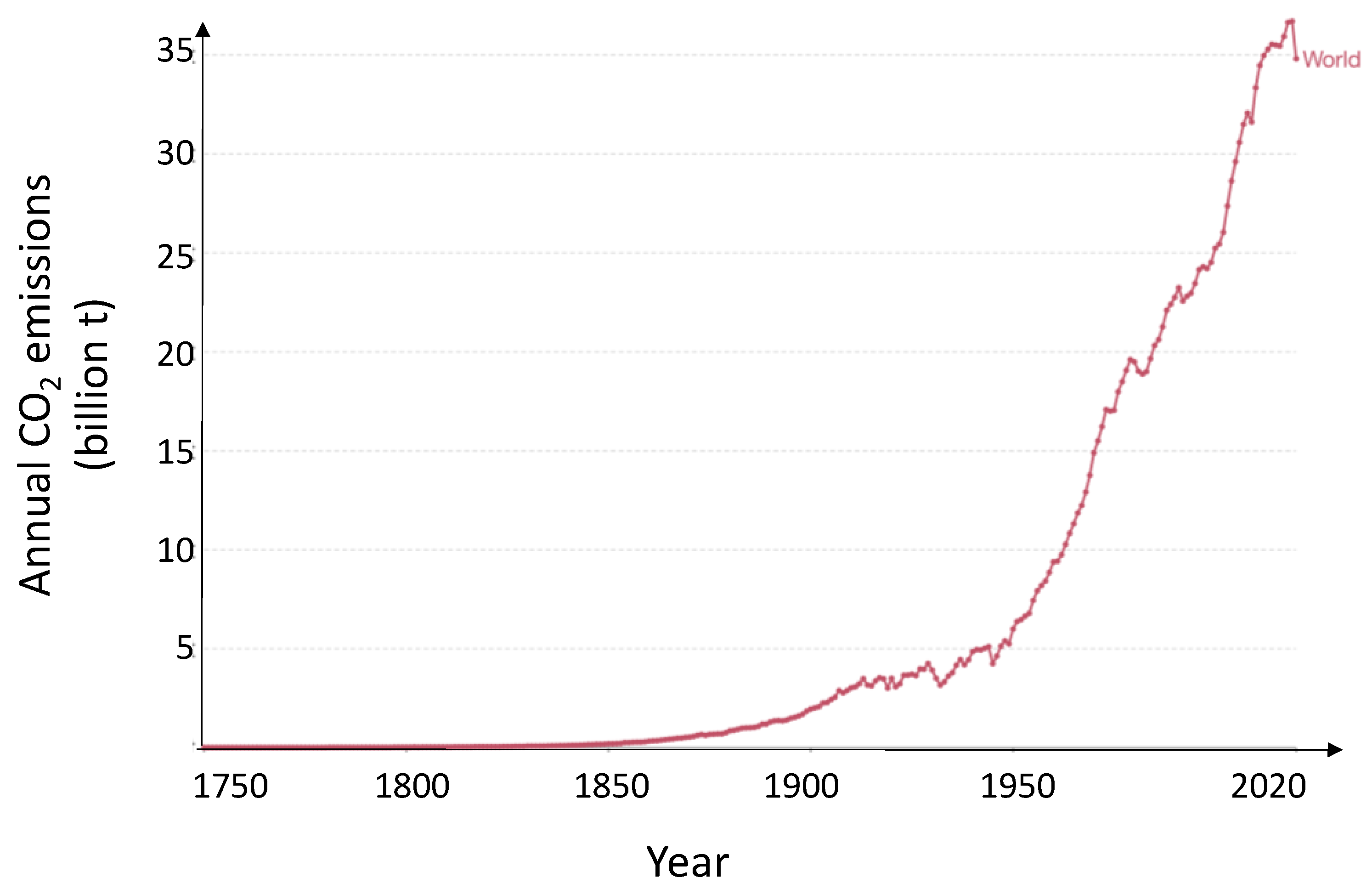
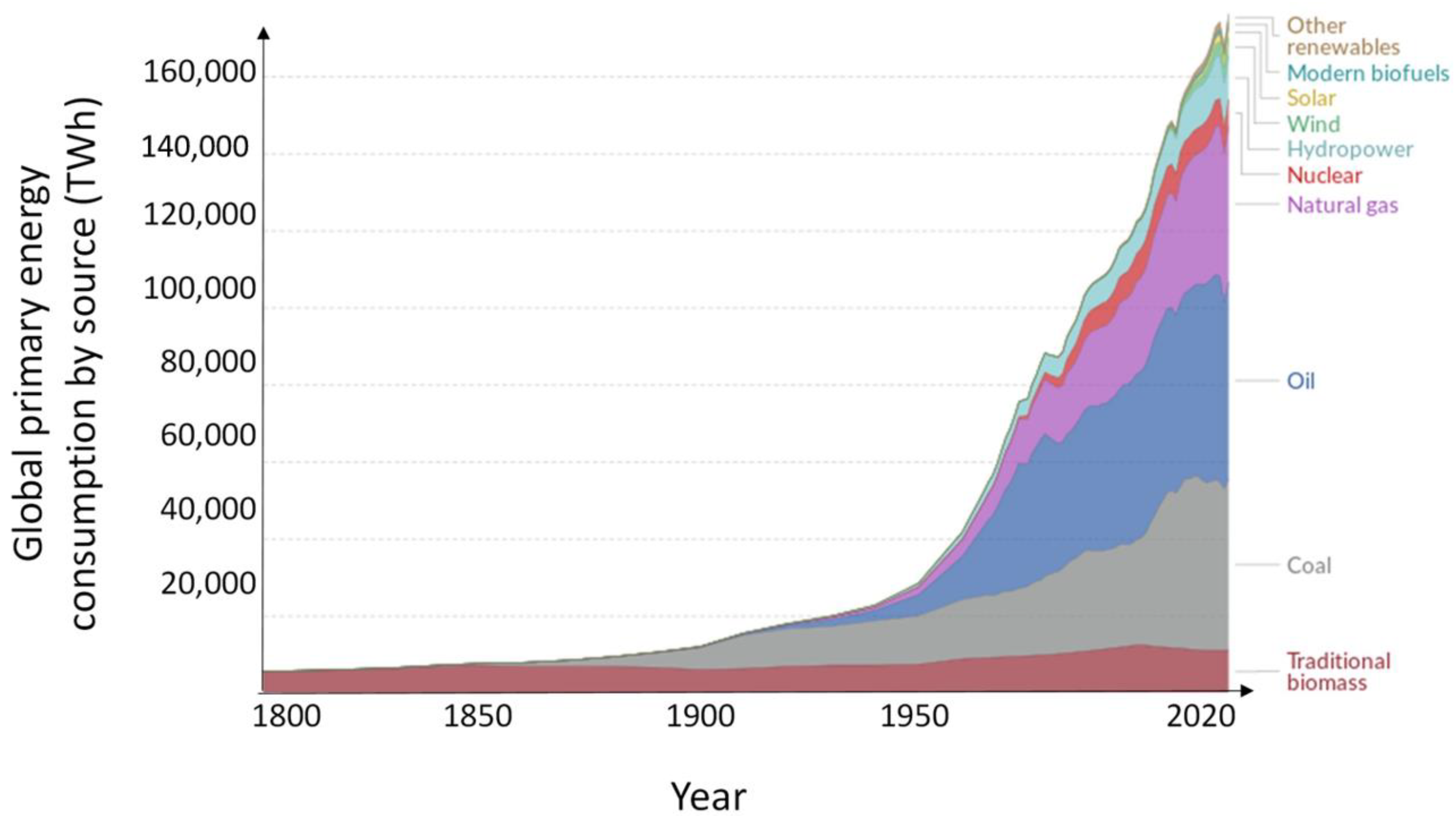


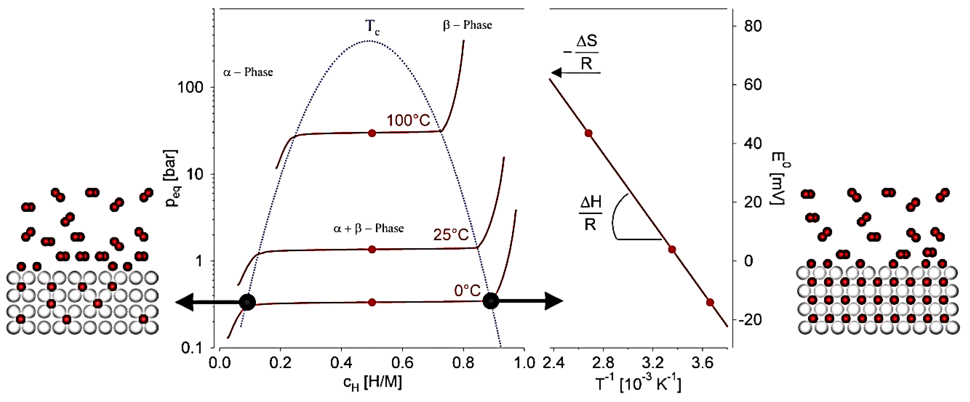


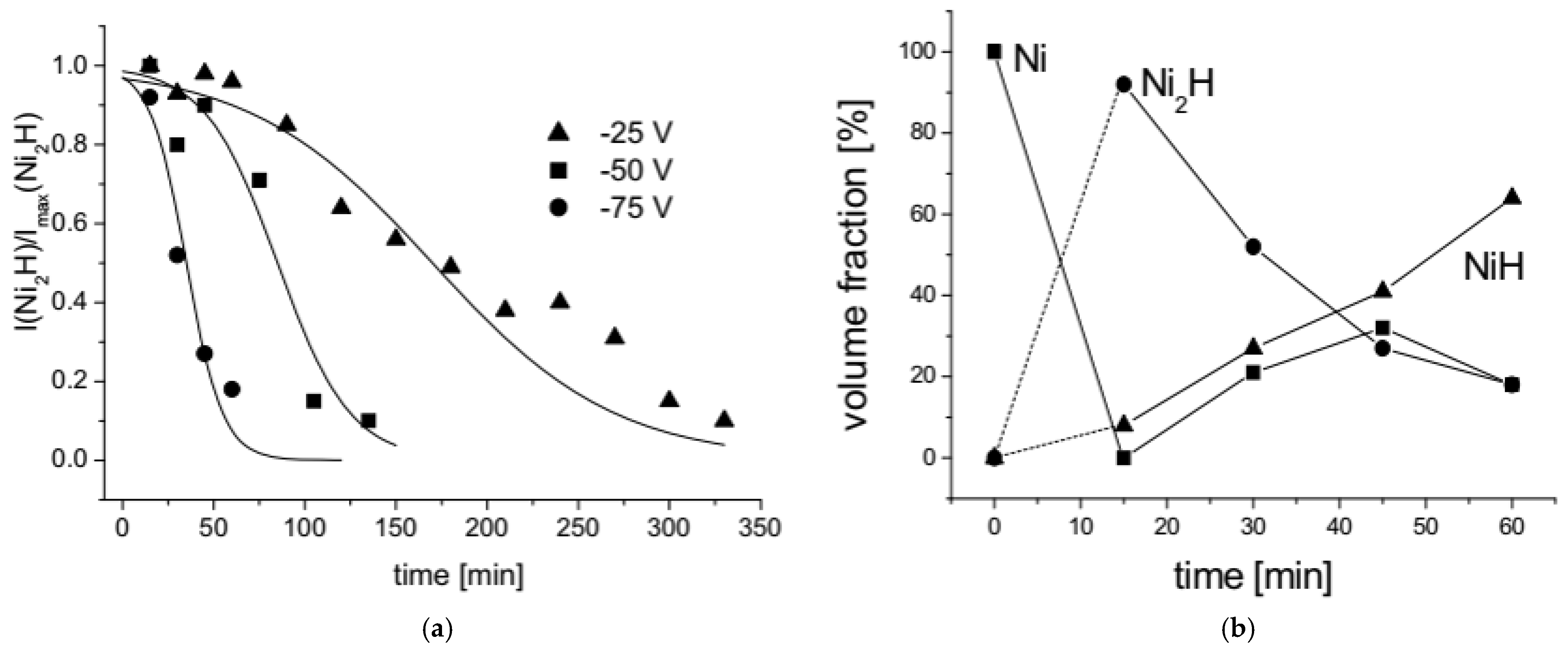


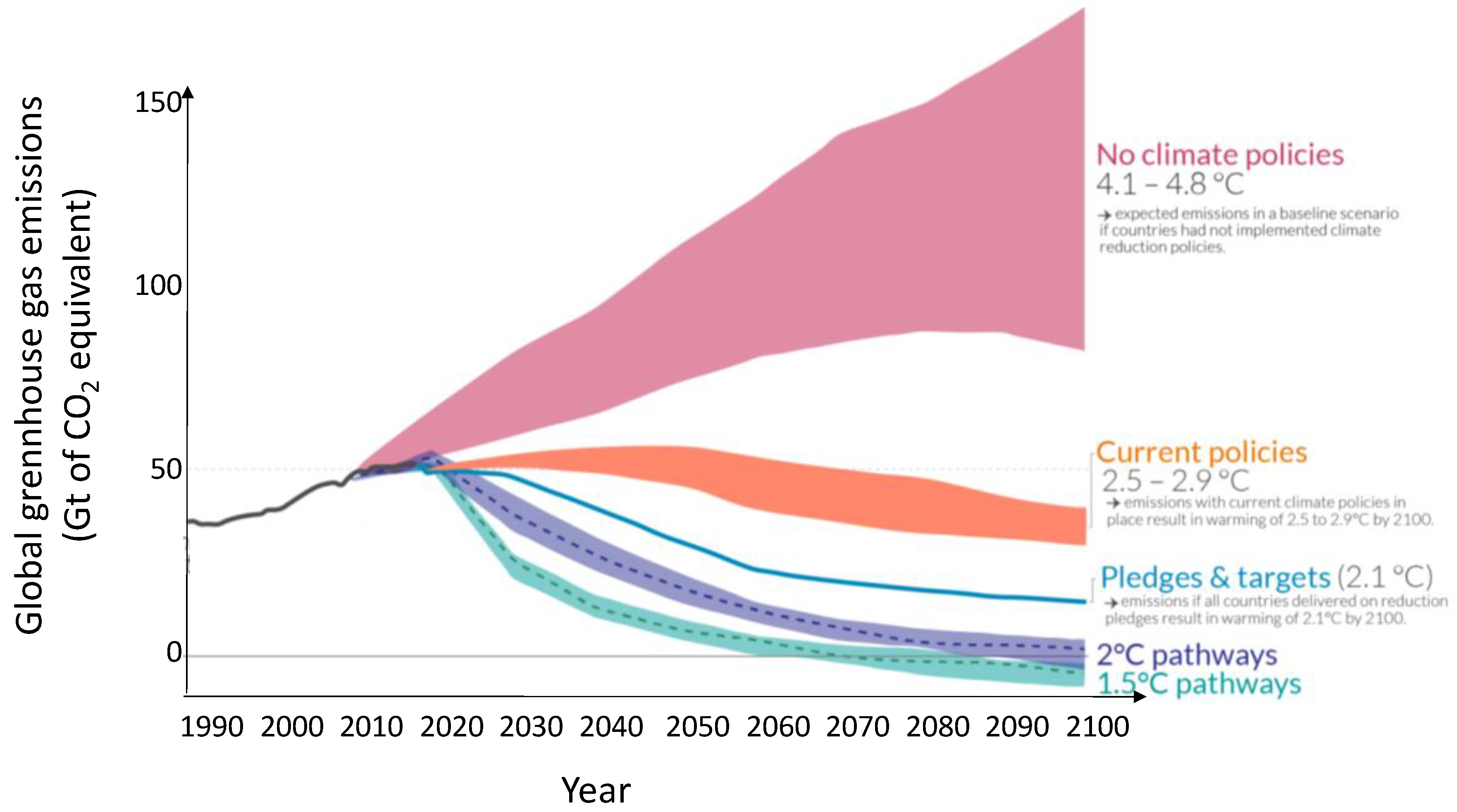
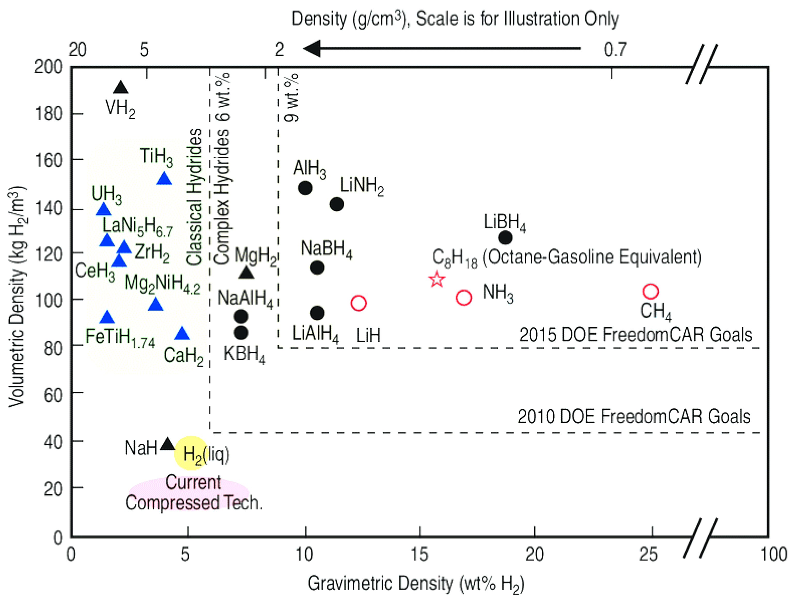
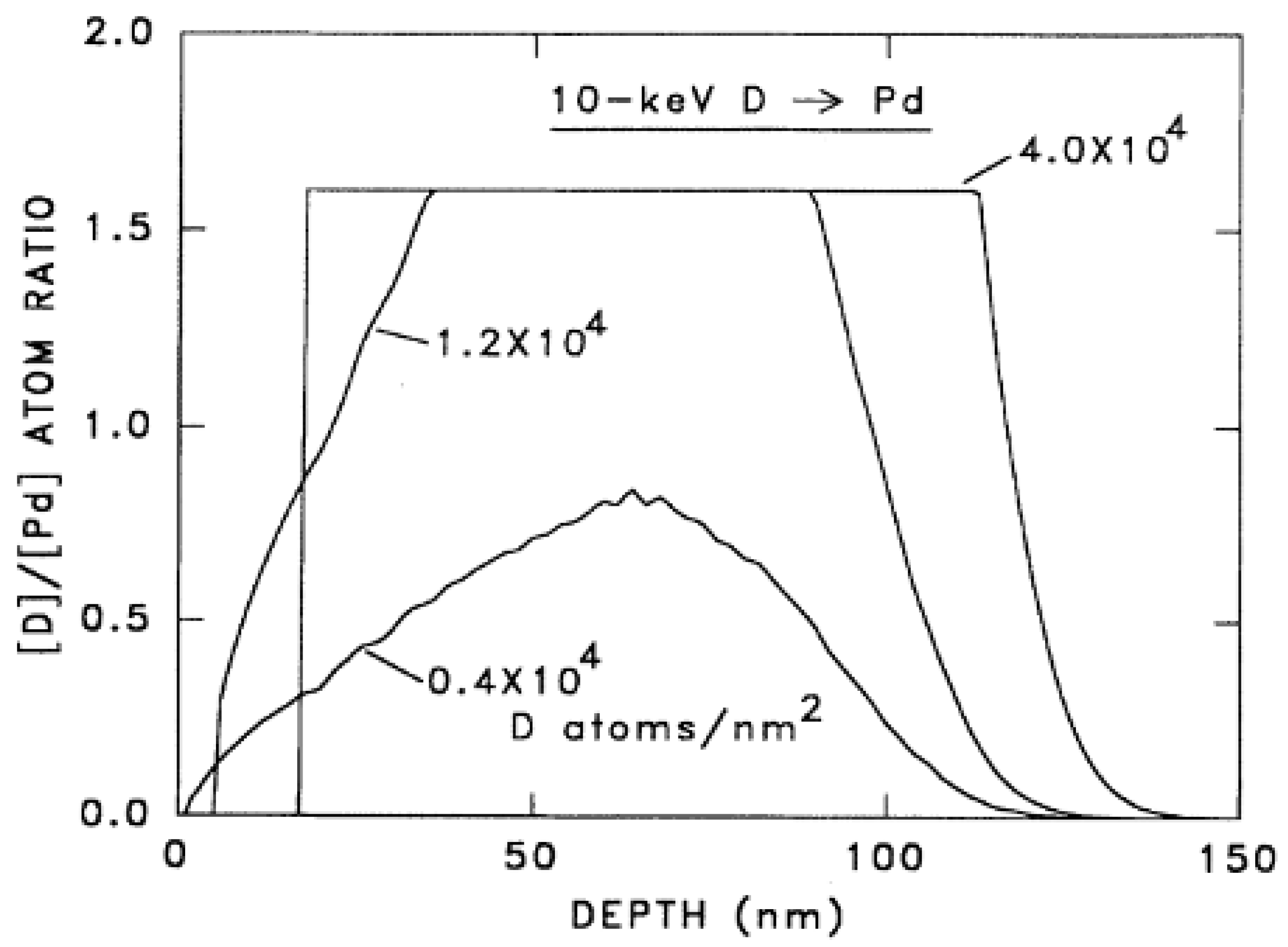
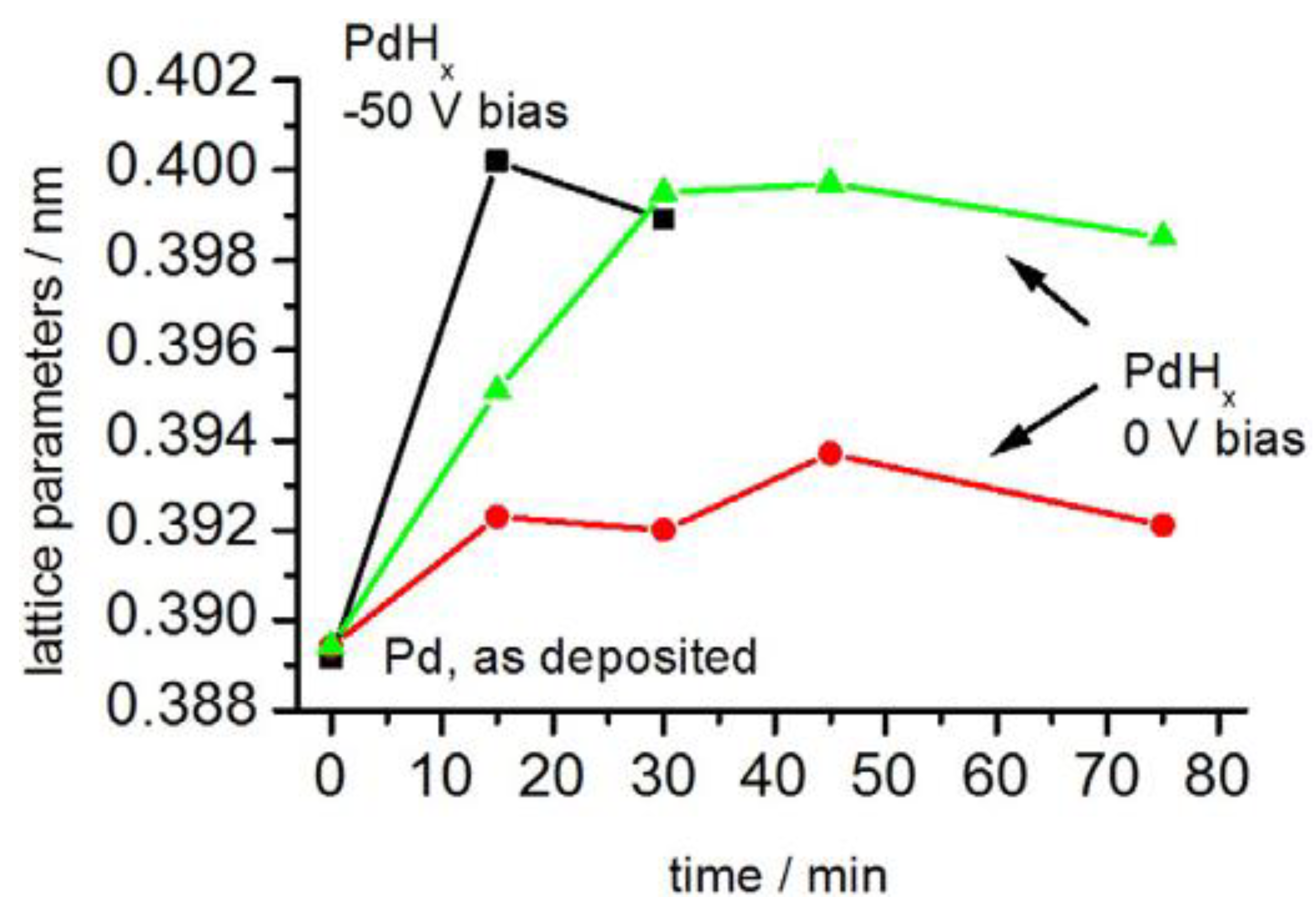
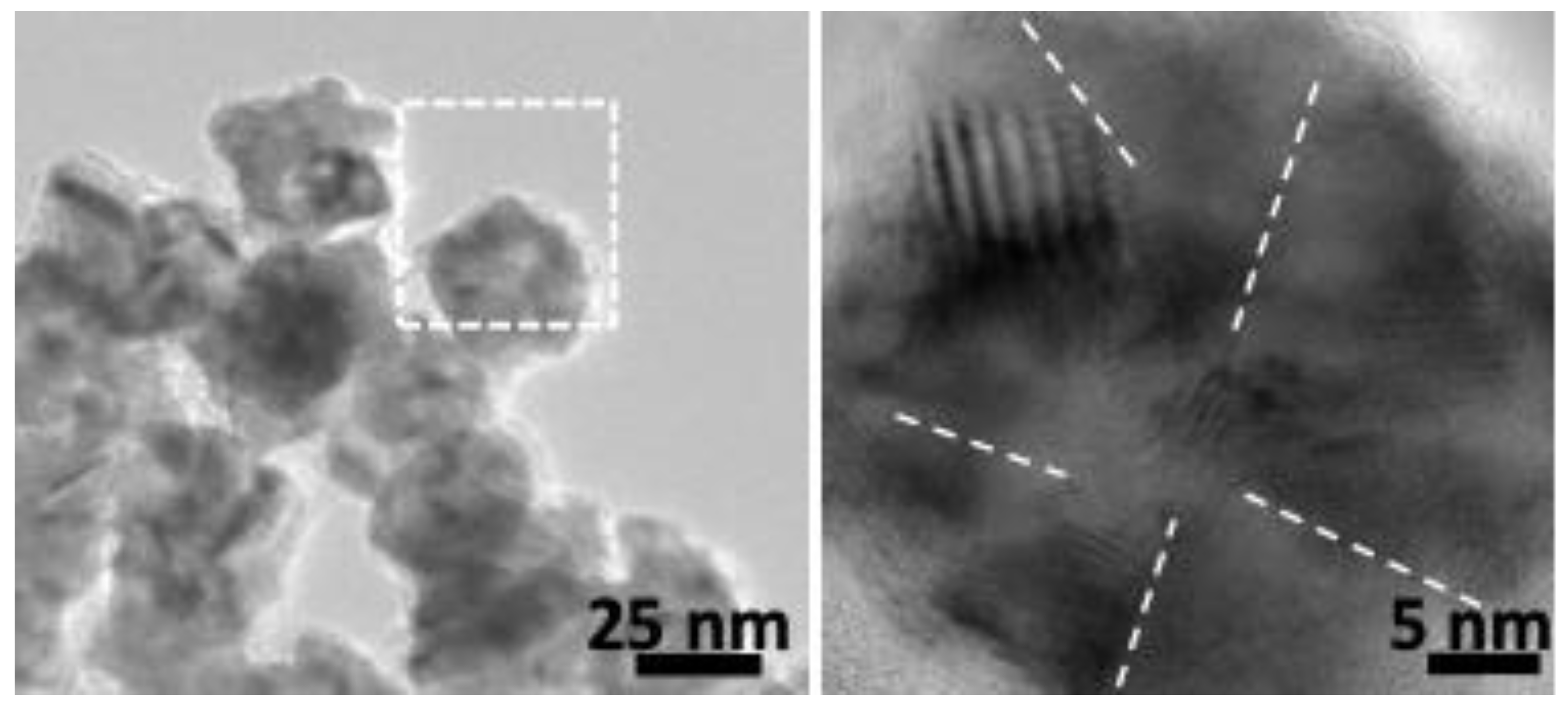
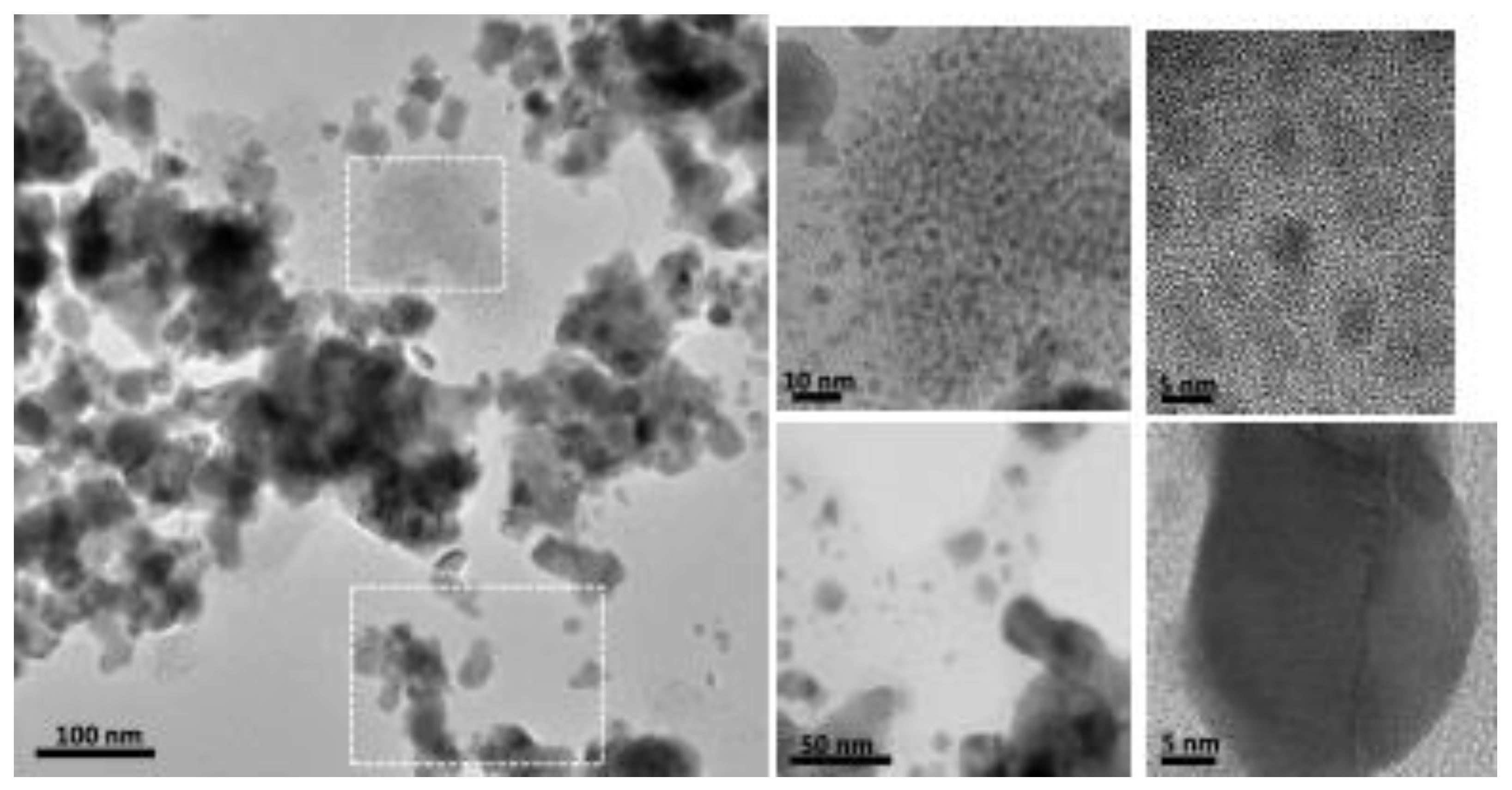