CFD Model of Refuelling through the Entire HRS Equipment: The Start-Up Phase Simulations
Abstract
:1. Introduction
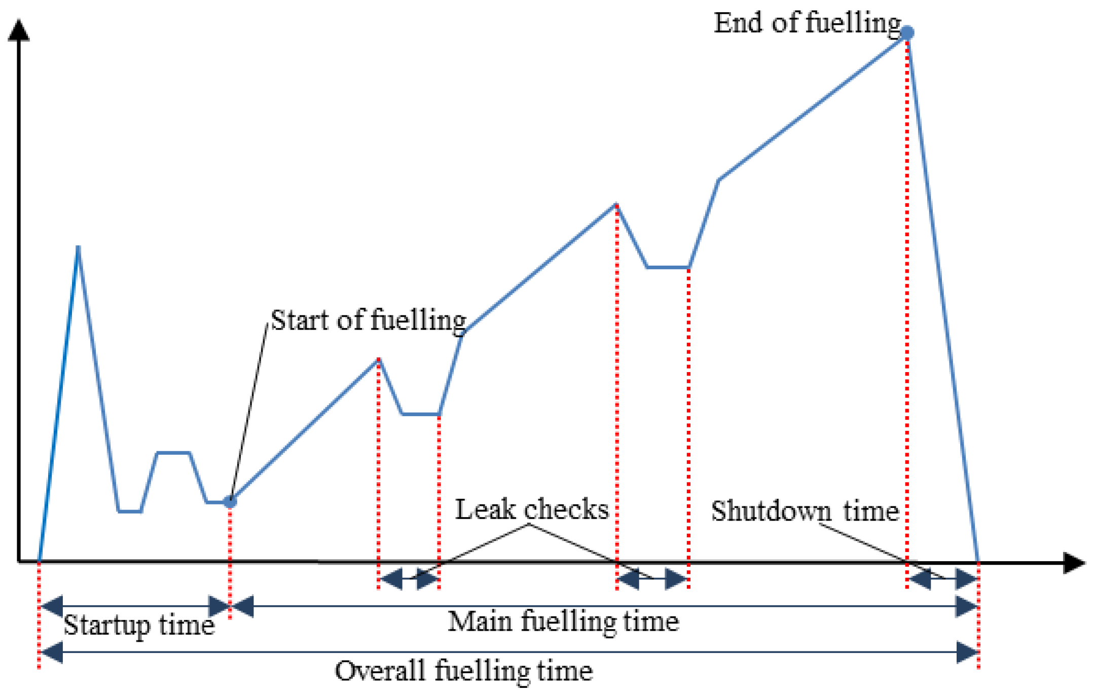
The Start-Up Phase of Refuelling
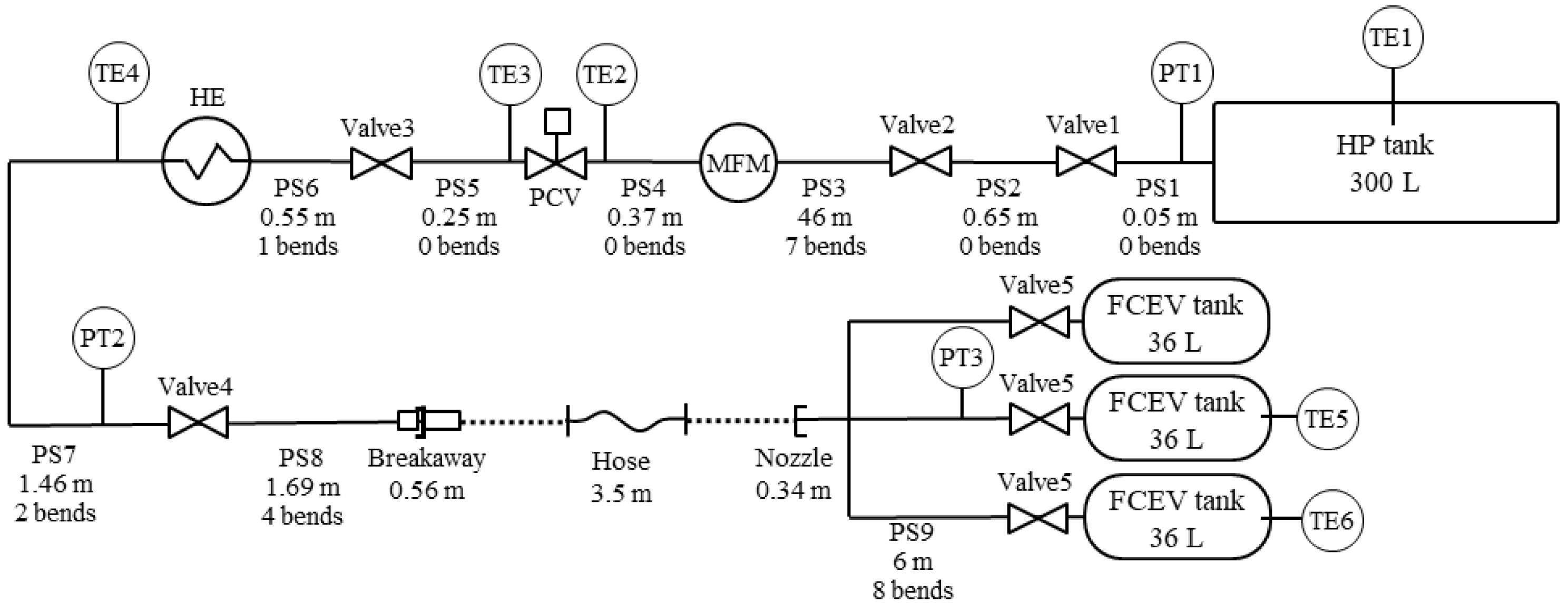
2. Validation Experiment
3. CFD Model
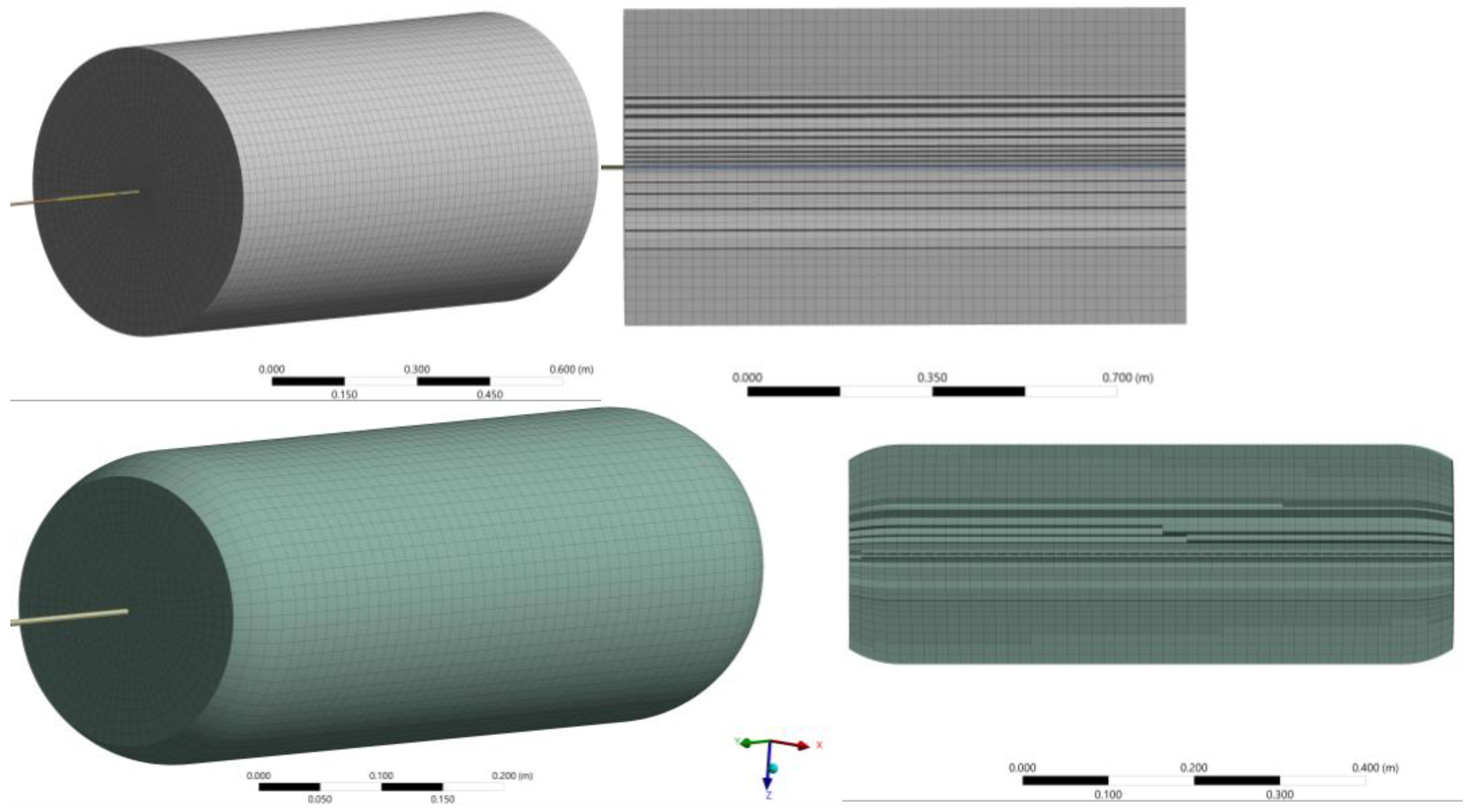
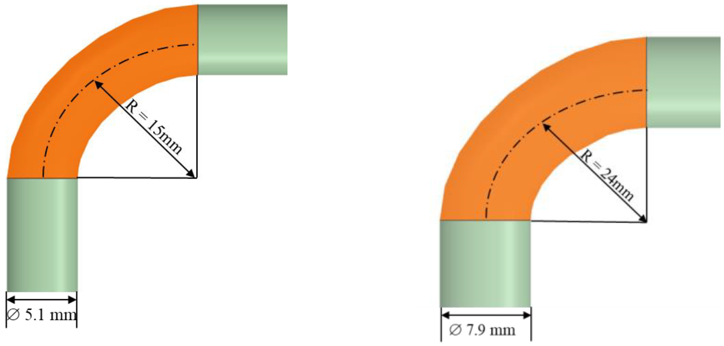
3.1. Calculation Domain and Parameters of HRS Components
3.2. Governing Equations and Numerical Details
3.3. Initial and Boundary Conditions
3.4. Modelling the PCV and the HE
4. Simulation Results and Discussion
5. Conclusions
Author Contributions
Funding
Data Availability Statement
Acknowledgments
Conflicts of Interest
Nomenclature
| C | Specific heat [J/kg/K)] | Sk, Sε | User-defined source terms for k [m2/s2] and ε [m3/s3] |
| C1ε, C2ε, C3ε | Standard k-ε model constants | t | Time [s] |
| Cd | Discharge coefficient [-] | ui, uj, uk | Velocity components [m/s] |
| Cp | Specific heat at constant pressure [J/kg/K] | xi, xj, xk | Cartesian coordinates [m] |
| Cv | Flow coefficient [-] | YM | Contribution of the fluctuating dilatation in compressible turbulence to the overall dissipation rate [-] |
| D | Diameter of tank [m] | ||
| D0 | Equivalent pipe diameter [m] | ||
| Normalised mass flow rate difference [-] | β | The ratio of the equivalent pipe diameter to the upstream pipe size [-] | |
| E | Total energy [J] | ||
| g | Gravity acceleration [m/s2] | γ | Ratio of specific heats [-] |
| Gb | Generation of turbulence kinetic energy due to buoyancy [-] | δ | Thickness [mm] |
| Gk | Generation of turbulence kinetic energy due to the mean velocity gradients [-] | δij | Kronecker symbol [-] |
| hext | External convection heat transfer coefficient [W/m2/K] | ε | Dissipation rate of turbulent kinetic energy [m2/s3] |
| k | Turbulent kinetic energy [J/kg] | λ | Thermal conductivity [W/m/K] |
| Simulated mass flow rate [kg/s] | μ | Molecular dynamic viscosity [Pa·s] | |
| Experimental mass flow rate [kg/s] | μt | Turbulent dynamic viscosity [Pa·s] | |
| P | Pressure [Pa] | ρ | Density [kg/m3] |
| Pinitial | Initial pressure in tanks [Pa] | σk, σε | Turbulent Prandtl numbers for k and ɛ [-] |
| Prt | Turbulent Prandtl number [-] | ||
| Acronyms | |||
| APRR | Average pressure ramp rate | CFRP | Carbon fibre-reinforced polymer |
| CFD | Computational fluid dynamics | HE | Heat exchanger |
| HDV | heavy-duty vehicles | HP | High pressure |
| HRS | Hydrogen refuelling station | L/D | Length to diameter |
| LDV | Light duty vehicles | MFM | Mass flow meter |
| NREL | National Renewable Energy Laboratory | NWP | Nominal working pressure |
| PCV | Pressure control valve | PID | Piping and instrumentation diagram |
| STP | Standard temperature and pressure | TMA | Triple moving average |
References
- De Miguel, N.; Acosta, B.; Baraldi, D.; Melideo, R.; Ortiz Cebolla, R.; Moretto, P. The role of initial tank temperature on refuelling of on-board hydrogen tanks. Int. J. Hydrogen Energy 2016, 41, 8606–8615. [Google Scholar] [CrossRef]
- United Nations Economic Commission for Europe. Global Registry. In Addendum 13: Global Technical Regulation No. 13; Global Technical Regulation on Hydrogen and Fuel Cell Vehicles; United Nations Economic Commission for Europe: Geneva, Switzerland, 2013. [Google Scholar]
- United Nations. Uniform Provisions Concerning the Approval of Motor Vehicles and Their Components with Regard to the Safety-Related Performance of Hydrogen-Fuelled Vehicles (HFCV) UN R134; Ece/Trans/Wp.29/2014/78; United Nations: New York, NY, USA, 2015. [Google Scholar]
- J2579_201806; Standard for Fuel Systems in Fuel Cell and Other Hydrogen Vehicles 2018. Fuel Cell Standards Committee: Warrendale, PA, USA, 2018. [CrossRef]
- J2601_202005; Fueling Protocols for Light Duty Gaseous Hydrogen Surface Vehicles, Rev 2020. Fuel Cell Standards Committee: Warrendale, PA, USA, 2020; pp. 1–2. [CrossRef]
- SAE J2601-2; Fueling Protocol for Gaseous Hydrogen Powered Heavy Duty Vehicles. SAE International: Warrendale, PA, USA, 2014.
- SAE J2601-3; Fueling Protocol for Gaseous Hydrogen Powered Industrial Trucks. SAE International: Warrendale, PA, USA, 2022.
- ISO/TS 15869; Gaseous Hydrogen and Hydrogen Blends—Land Vehicle Fuel Tanks. ISO: Geneva, Switzerland, 2009.
- Sun, K.; Li, Z. Development of emergency response strategies for typical accidents of hydrogen fuel cell electric vehicles. Int. J. Hydrogen Energy 2021, 46, 37679–37696. [Google Scholar] [CrossRef]
- Lazarenko, O.; Parkhomenko, V.-P.; Sukach, R.; Bilonozhko, B.; Kuskovets, A. Design Features and Hazards of Hydrogen Fuel Cell Cars. Fire Saf. 2021, 37, 52–57. [Google Scholar] [CrossRef]
- Zheng, J.; Guo, J.; Yang, J.; Zhao, Y.; Zhao, L.; Pan, X.; Ma, J.; Zhang, L. Experimental and numerical study on temperature rise within a 70 MPa type III cylinder during fast refueling. Int. J. Hydrogen Energy 2013, 38, 10956–10962. [Google Scholar] [CrossRef]
- Melideo, D.; Baraldi, D.; Galassi, M.C.; Ortiz Cebolla, R.; Acosta Iborra, B.; Moretto, P. CFD model performance benchmark of fast filling simulations of hydrogen tanks with pre-cooling. Int. J. Hydrogen Energy 2014, 39, 4389–4395. [Google Scholar] [CrossRef]
- Bourgeois, T.; Brachmann, T.; Barth, F.; Ammouri, F.; Baraldi, D.; Melideo, D.; Acosta-Iborra, B.; Zaepffel, D.; Saury, D.; Lemonnier, D. Optimization of hydrogen vehicle refuelling requirements. Int. J. Hydrogen Energy 2017, 42, 13789–13809. [Google Scholar] [CrossRef]
- Hosseini, M.; Dincer, I.; Naterer, G.F.; Rosen, M.A. Thermodynamic analysis of filling compressed gaseous hydrogen storage tanks. Int. J. Hydrogen Energy 2012, 37, 5063–5071. [Google Scholar] [CrossRef]
- Molkov, V.; Dadashzadeh, M.; Makarov, D. Physical model of onboard hydrogen storage tank thermal behaviour during fuelling. Int. J. Hydrogen Energy 2019, 44, 4374–4384. [Google Scholar] [CrossRef]
- Bai, Y.; Zhang, C.; Duan, H.; Jiang, S.; Zhou, Z.; Grouset, D.; Zhang, M.; Ye, X. Modeling and optimal control of fast filling process of hydrogen to fuel cell vehicle. J. Energy Storage 2021, 35, 102306. [Google Scholar] [CrossRef]
- Kuroki, T.; Sakoda, N.; Shinzato, K.; Monde, M.; Takata, Y. Dynamic simulation for optimal hydrogen refueling method to Fuel Cell Vehicle tanks. Int. J. Hydrogen Energy 2018, 43, 5714–5721. [Google Scholar] [CrossRef]
- Charolais, A.; Ammouri, F.; Vyazmina, E.; Nouvelot, Q.; Guewouo, T.; Greisel, M.; Gebhard, M.; Kuroki, T.; Mathison, S. Protocol for heavy duty hydrogen refueling: A modeling benchmark. In Proceedings of the International Conference on Hydrogen Safety (ICHS2021), Edinburgh, UK, 21–24 September 2021; pp. 1150–1160. [Google Scholar]
- Kuroki, T.; Nagasawa, K.; Peters, M.; Leighton, D.; Kurtz, J.; Sakoda, N.; Monde, M.; Takata, Y. Thermodynamic modeling of hydrogen fueling process from high-pressure storage tank to vehicle tank. Int. J. Hydrogen Energy 2021, 46, 22004–22017. [Google Scholar] [CrossRef]
- Carrere, P.; Lodiar, G.; Vyazmina, E.; Ammouri, F.; Charolais, A. CFD simulations of the refueling of long horizontal H2 tanks. In Proceedings of the International Conference on Hydrogen Safety (ICHS2021), Edinburgh, UK, 21–24 September 2021; pp. 1175–1184. [Google Scholar]
- Melideo, D.; Baraldi, D. CFD analysis of fast filling strategies for hydrogen tanks and their effects on key-parameters. Int. J. Hydrogen Energy 2015, 40, 735–745. [Google Scholar] [CrossRef]
- Melideo, D.; Baraldi, D.; Acosta-Iborra, B.; Cebolla, R.O.; Moretto, P. Cfd Investigation of Filling and Emptying of Hydrogen Tanks. In Proceedings of the International Conference on Hydrogen Safety, Yokohama, Japan, 19–21 October 2015; pp. 1–12. [Google Scholar]
- Melideo, D.; Baraldi, D.; Galassi, M.C.; Ortiz Cebolla, R.; Acosta Iborra, B.; Moretto, P. Assessment of a CFD Model for the Simulation of Fast Filling of Hydrogen Tanks With Pre-Cooling. In Proceedings of the International Conference on Hydrogen Safety, Edinburgh, UK, 21–24 September 2021; pp. 1–11. [Google Scholar]
- Heitsch, M.; Baraldi, D.; Moretto, P. Numerical investigations on the fast filling of hydrogen tanks. Int. J. Hydrogen Energy 2011, 36, 2606–2612. [Google Scholar] [CrossRef]
- Ramasamy, V.; Richardson, E.S. Thermal response of high-aspect-ratio hydrogen cylinders undergoing fast-filling. Int. J. Heat Mass Transf. 2020, 160, 120179. [Google Scholar] [CrossRef]
- Bourgeois, T.; Ammouri, F.; Baraldi, D.; Moretto, P. The temperature evolution in compressed gas filling processes: A review. Int. J. Hydrogen Energy 2018, 43, 2268–2292. [Google Scholar] [CrossRef]
- Molkov, V.; Dadashzadeh, M.; Kashkarov, S.; Makarov, D. Performance of hydrogen storage tank with TPRD in an engulfing fire. Int. J. Hydrogen Energy 2021, 46, 36581–36597. [Google Scholar] [CrossRef]
- Miller, R. Flow Measurement Engineering Handbook, 3rd ed.; McGraw-Hill: New York, NY, USA, 1983. [Google Scholar]
- Lemmon, E.W.; Bell, I.H.; Huber, M.L.; McLinden, M.O. NIST Standard Reference Database 23: Reference Fluid Thermodynamic and Transport Properties-REFPROP, Version 10.0; National Institute of Standards and Technology, Standard Reference Data Program: Gaithersburg, MD, USA, 2018. [CrossRef]
- Launder, B.E.; Spalding, D.B. The numerical computation of turbulent flows. Comput. Methods Appl. Mech. Eng. 1974, 3, 269–289. [Google Scholar] [CrossRef]
- Ansys Inc. Ansys® Fluent 2020 R2 User Manual 2020. Available online: https://ansyshelp.ansys.com/account/secured?returnurl=/Views/Secured/corp/v202/en/ (accessed on 4 February 2023).
- Ebne-Abbasi, H.; Makarov, D.; Molkov, V. CFD modelling of the entire fuelling process at a hydrogen refuelling station. In Proceedings of the International Seminar on Fire and Explosion Hazards (ISFEH10), Oslo, Norway, 22–27 May 2022; pp. 22–27. [Google Scholar]
- Simonovski, I.; Baraldi, D.; Melideo, D.; Acosta-Iborra, B. Thermal simulations of a hydrogen storage tank during fast filling. Int. J. Hydrogen Energy 2015, 40, 12560–12571. [Google Scholar] [CrossRef]
- Hart, N.; Sinding, C.D.; Mathison, S.; Quong, S.; Mattelaer, V.; Ruiz, A.; Grab, A.; Kvasnicka, A.; Spitta, C.; Ammouri, F.; et al. PRHYDE Results as Input for Standardisation. Deliverable D6.7. 2022. Available online: https://lbst.de/prhyde/?lang=en (accessed on 25 January 2023).




| Parameter | Valve1 | Valve2 | MFM | PCV | Valve3 | HE | Valve4 | Valve5 |
|---|---|---|---|---|---|---|---|---|
| Flow coefficient, Cv [28] | 1.3 | 0.75 | 1.0 | 1.0 | 0.75 | 1.0 | 0.75 | 1.0 |
| Calculated equivalent ID [mm] | 6.5 | 4.99 | 5.76 | 5.76 | 4.99 | 5.76 | 4.99 | 5.76 |
| Upstream pipe diameter [mm] | 7.9 | 5.1 | 5.1 | 5.1 | 5.1 | 5.1 | 5.1 | 5.1 |
| Downstream pipe diameter [mm] | 7.9 | 7.9 | 5.1 | 5.1 | 5.1 | 5.1 | 5.1 | 5.1 |
Disclaimer/Publisher’s Note: The statements, opinions and data contained in all publications are solely those of the individual author(s) and contributor(s) and not of MDPI and/or the editor(s). MDPI and/or the editor(s) disclaim responsibility for any injury to people or property resulting from any ideas, methods, instructions or products referred to in the content. |
© 2023 by the authors. Licensee MDPI, Basel, Switzerland. This article is an open access article distributed under the terms and conditions of the Creative Commons Attribution (CC BY) license (https://creativecommons.org/licenses/by/4.0/).
Share and Cite
Molkov, V.; Ebne-Abbasi, H.; Makarov, D. CFD Model of Refuelling through the Entire HRS Equipment: The Start-Up Phase Simulations. Hydrogen 2023, 4, 585-598. https://doi.org/10.3390/hydrogen4030038
Molkov V, Ebne-Abbasi H, Makarov D. CFD Model of Refuelling through the Entire HRS Equipment: The Start-Up Phase Simulations. Hydrogen. 2023; 4(3):585-598. https://doi.org/10.3390/hydrogen4030038
Chicago/Turabian StyleMolkov, Vladimir, Hazhir Ebne-Abbasi, and Dmitriy Makarov. 2023. "CFD Model of Refuelling through the Entire HRS Equipment: The Start-Up Phase Simulations" Hydrogen 4, no. 3: 585-598. https://doi.org/10.3390/hydrogen4030038
APA StyleMolkov, V., Ebne-Abbasi, H., & Makarov, D. (2023). CFD Model of Refuelling through the Entire HRS Equipment: The Start-Up Phase Simulations. Hydrogen, 4(3), 585-598. https://doi.org/10.3390/hydrogen4030038


