
Metal-Hydride-Based Hydrogen Storage as Potential Heat Source for the Cold Start of PEM FC in Hydrogen-Powered Coaches: A Comparative Study of Various Materials and Thermal Management Techniques


Abstract
:1. Introduction
2. Methodology
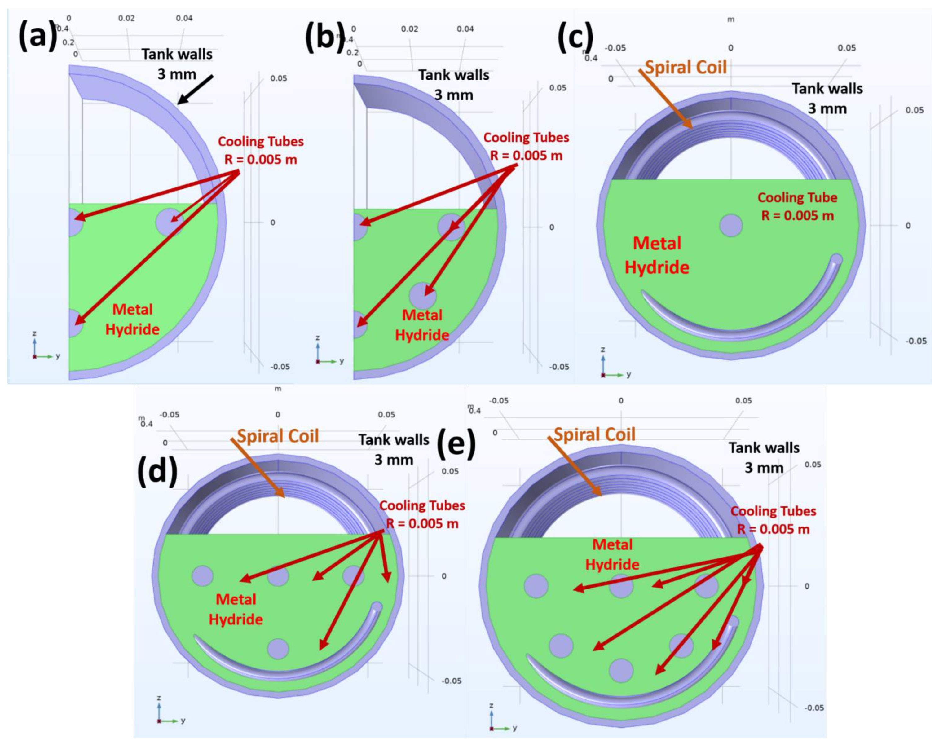
2.1. Tank Geometries and Thermal Management Scenarios
2.2. Numerical Model
2.2.1. Assumptions of the Numerical Model
- (a)
- The medium is in a local thermal equilibrium, which implies that there is no heat transfer between solid and gas phases.
- (b)
- The temperature and pressure profiles are initially uniform.
- (c)
- Hydrogen is treated as an ideal gas from a thermodynamic point of view. This is an assumption that sometimes might be far from the reality and might affect the accuracy of the model. In case the hydrogen pressure is below 20 bar and room temperature, this is, in general, an acceptable assumption supported by the literature [34,35,36]. However, this assumption must not be made when the pressure of the system is higher. For the analysis of a hydride-based hydrogen compressor, the compressibility factor must be considered when the density of the gas is calculated and updated [15]. Just for the comparison, the compressibility factor for a pressure of 20 bar, temperature of 10 °C and 100 g H2 is Z = 1.079804 whereas for pressure of 300 bar (middle stage for a 700 bar compressor) the compressibility factor is Z = 1.25 [37]. (The compressibility factor for ideal gas is 1.)
- (d)
- Thermal conductivity and specific heat capacity are assumed to be constant.
- (e)
- The porosity remains constant and uniform during hydrogenation.
- (f)
- The characteristics (the kinetics and thermal properties) of the bed are unaffected by the number of loading and unloading cycles. Thus, bed aging is neglected.
- (g)
- The metal hydride bed fills the entire space between the cooling tubes and the spiral heat exchanger (perfect packing condition).
2.2.2. Heat Equation
2.2.3. Hydrogen Mass Balance
2.2.4. Momentum Equation
2.2.5. Hydrogenation Kinetic Expression
2.2.6. Equilibrium Pressure
3. Validation of the Numerical Model
4. Results and Discussion
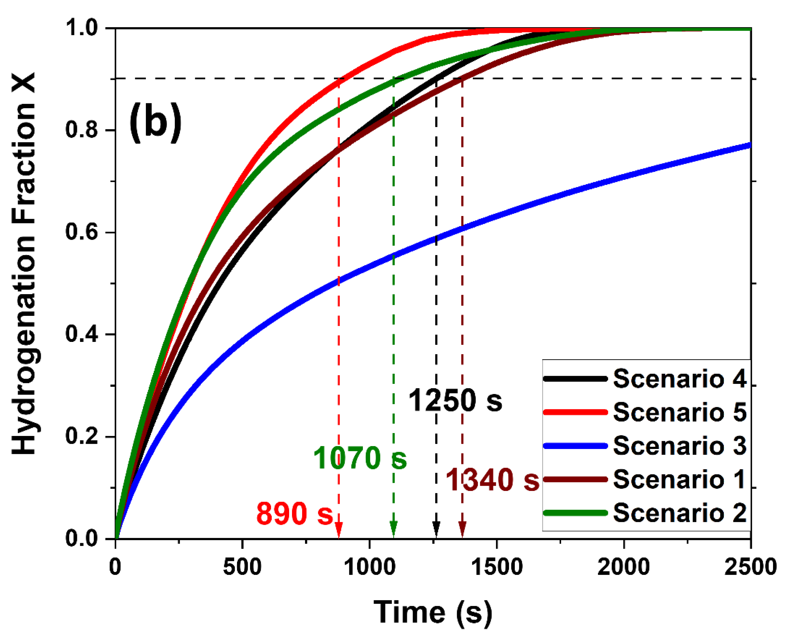
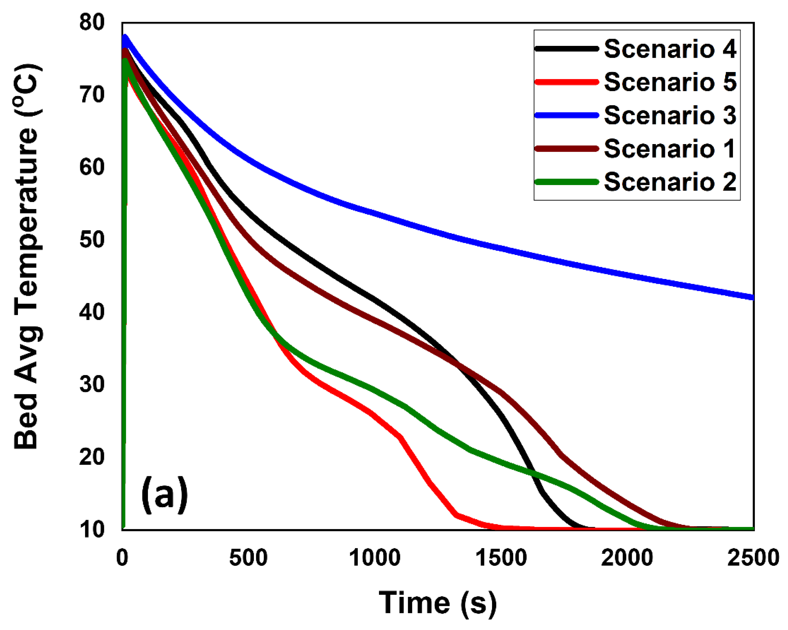
4.1. Temperature Distribution and Hydrogenation Kinetics
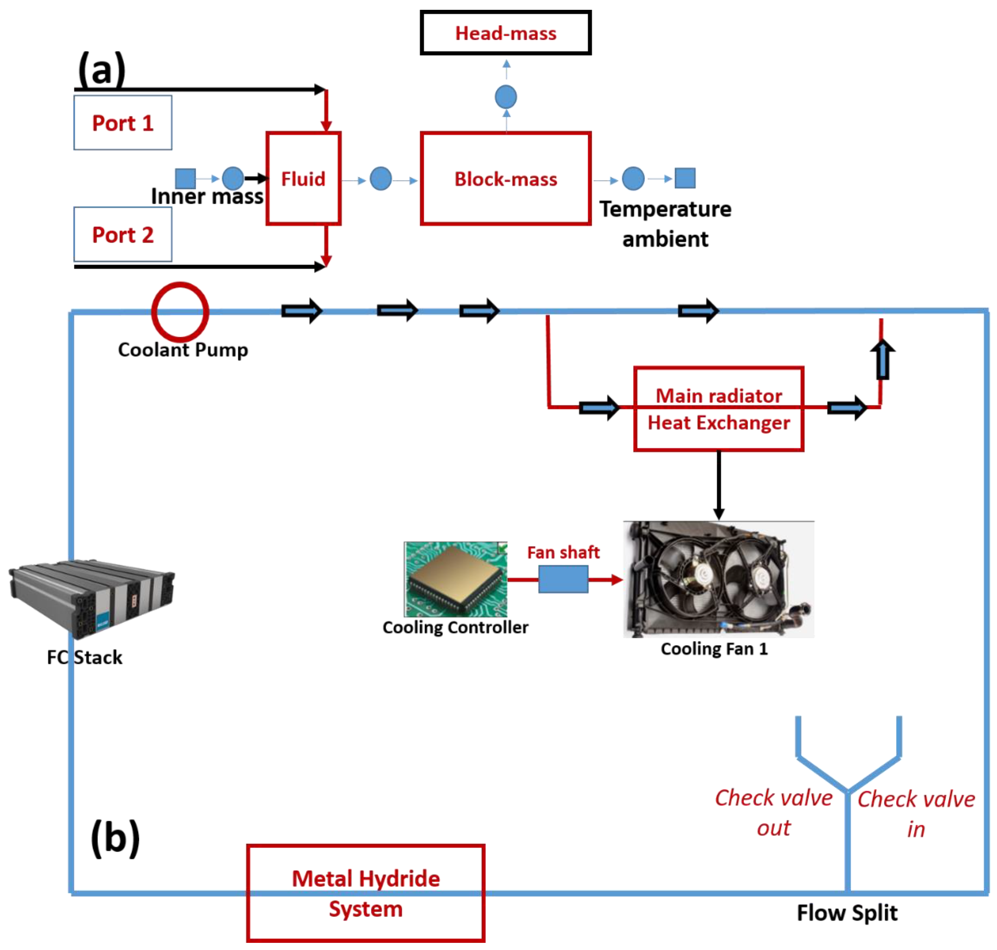
4.2. Thermal Coupling of the Metal Hydride and the PEMFC
5. Conclusions
Supplementary Materials
Author Contributions
Funding
Conflicts of Interest
References
- Meyer, Q.; Ashton, S.; Curnick, O.; Reisch, T.; Adcock, P.; Ronaszegi, K.; Robinson, J.B.; Brett, D.J.L. Dead-Ended Anode Polymer Electrolyte Fuel Cell Stack Operation Investigated Using Electrochemical Impedance Spectroscopy, off-Gas Analysis and Thermal Imaging. J. Power Sources 2014, 254, 1–9. [Google Scholar] [CrossRef]
- Khzouz, M.; Gkanas, E.I.; Shao, J.; Sher, F.; Beherskyi, D.; El-Kharouf, A.; Al Qubeissi, M. Life Cycle Costing Analysis: Tools and Applications for Determining Hydrogen Production Cost for Fuel Cell Vehicle Technology. Energies 2020, 13, 3783. [Google Scholar] [CrossRef]
- Nishimura, A.; Toyoda, K.; Mishima, D.; Ito, S.; Hu, E. Numerical Analysis on Impact of Thickness of PEM and GDL with and without MPL on Coupling Phenomena in PEFC Operated at Higher Temperature Such as 363 K and 373 K. Energies 2022, 15, 5936. [Google Scholar] [CrossRef]
- Tawalbeh, M.; Alarab, S.; Al-Othman, A.; Javed, R.M.N. The Operating Parameters, Structural Composition, and Fuel Sustainability Aspects of PEM Fuel Cells: A Mini Review. Fuels 2022, 3, 449–474. [Google Scholar] [CrossRef]
- D’Souza, C.; Apicella, M.; El-kharouf, A.; Stamatakis, E.; Khzouz, M.; Stubos, A.; Gkanas, E.I. Thermal Characteristics of an Air-Cooled Open-Cathode Proton Exchange Membrane Fuel Cell Stack via Numerical Investigation. Int. J. Energy Res. 2020, 44, 11597–11613. [Google Scholar] [CrossRef]
- Nyamsi, S.N.; Tolj, I.; Gęca, M.J. Dehydrogenation of Metal Hydride Reactor-Phase Change Materials Coupled with Light-Duty Fuel Cell Vehicles. Energies 2022, 15, 2982. [Google Scholar] [CrossRef]
- Yang, Y.; Jia, H.; Liu, Z.; Bai, N.; Zhang, X.; Cao, T.; Zhang, J.; Zhao, P.; He, X. Overall and Local Effects of Operating Parameters on Water Management and Performance of Open-Cathode PEM Fuel Cells. Appl. Energy 2022, 315, 118978. [Google Scholar] [CrossRef]
- Gkanas, E.I. Metal Hydrides: Modeling of Metal Hydrides to Be Operated in a Fuel Cell. In Portable Hydrogen Energy Systems; Ferreira-Aparicio, P., Chaparro, A.M., Eds.; Academic Press: Cambridge, MA, USA, 2018; pp. 67–90. ISBN 978-0-12-813128-2. [Google Scholar]
- Gkanas, E.I.; Statheros, T.; Khzouz, M. Heat Management on Rectangular Metal Hydride Tanks for Green Building Applications. Int. J. Hydrogen Energy 2019, 44, 19267–19274. [Google Scholar] [CrossRef]
- Xu, Z.; Zhao, N.; Hillmansen, S.; Roberts, C.; Yan, Y. Techno-Economic Analysis of Hydrogen Storage Technologies for Railway Engineering: A Review. Energies 2022, 15, 6467. [Google Scholar] [CrossRef]
- Krane, P.; Nash, A.L.; Ziviani, D.; Braun, J.E.; Marconnet, A.M.; Jain, N. Dynamic Modeling and Control of a Two-Reactor Metal Hydride Energy Storage System. Appl. Energy 2022, 325, 119836. [Google Scholar] [CrossRef]
- Gkanas, E.I.; Damian, A.; Ioannidou, A.; Stoian, G.; Lupu, N.; Gjoka, M.; Makridis, S.S. Synthesis, Characterisation and Hydrogen Sorption Properties of Mechanically Alloyed Mg(Ni1-XMnx)2. Mater. Today Energy 2019, 13, 186–194. [Google Scholar] [CrossRef]
- Tan, J.; Chai, M.; He, K.; Chen, Y. Numerical Simulation on Heating Effects during Hydrogen Absorption in Metal Hydride Systems for Hydrogen Storage. Energies 2022, 15, 2673. [Google Scholar] [CrossRef]
- Malleswararao, K.; Dutta, P.; Murthy, S.S. Applications of Metal Hydride Based Thermal Systems: A Review. Appl. Therm. Eng. 2022, 215, 118816. [Google Scholar] [CrossRef]
- Gkanas, E.I.; Stamatakis, E.; Christodoulou, C.N.; Tzamalis, G.; Karagiorgis, G.; Chroneos, A.; Kuganathan, N.; Khzouz, M.; Stubos, A.K. Study on the Operation and Energy Demand of Dual-Stage Metal Hydride Hydrogen Compressors under Effective Thermal Management. Int. J. Hydrogen Energy 2021, 46, 29272–29287. [Google Scholar] [CrossRef]
- Gkanas, E.I.; Grant, D.M.; Stuart, A.D.; Eastwick, C.N.; Book, D.; Nayebossadri, S.; Pickering, L.; Walker, G.S. Numerical Study on a Two-Stage Metal Hydride Hydrogen Compression System. J. Alloys Compd. 2015, 645, S18–S22. [Google Scholar] [CrossRef]
- Lototskyy, M.; Linkov, V. Thermally Driven Hydrogen Compression Using Metal Hydrides. Int. J. Energy Res. 2022. [Google Scholar] [CrossRef]
- Luo, Y.; Wang, Q.; Li, J.; Xu, F.; Sun, L.; Zou, Y.; Chu, H.; Li, B.; Zhang, K. Enhanced Hydrogen Storage/Sensing of Metal Hydrides by Nanomodification. Mater. Today Nano 2020, 9, 100071. [Google Scholar] [CrossRef]
- Gkanas, E.I.; Khzouz, M.; Panagakos, G.; Statheros, T.; Mihalakakou, G.; Siasos, G.I.; Skodras, G.; Makridis, S.S. Hydrogenation Behavior in Rectangular Metal Hydride Tanks under Effective Heat Management Processes for Green Building Applications. Energy 2018, 142, 518–530. [Google Scholar] [CrossRef]
- Nguyen, H.Q.; Shabani, B. Review of Metal Hydride Hydrogen Storage Thermal Management for Use in the Fuel Cell Systems. Int. J. Hydrogen Energy 2021, 46, 31699–31726. [Google Scholar] [CrossRef]
- Keith, M.D.; Kukkapalli, V.K.; Kim, S. Phase Change Cooling of a Metal Hydride Reactor for Rapid Hydrogen Absorption. Energies 2022, 15, 2490. [Google Scholar] [CrossRef]
- Gkanas, E.I.; Makridis, S.S.; Stubos, A.K. Modeling and Simulation for Absorption-Desorption Cyclic Process on a Three-Stage Metal Hydride Hydrogen Compressor. Comput. Aided Chem. Eng. 2013, 32, 379–384. [Google Scholar] [CrossRef]
- MacDonald, B.D.; Rowe, A.M. Impacts of External Heat Transfer Enhancements on Metal Hydride Storage Tanks. Int. J. Hydrogen Energy 2006, 31, 1721–1731. [Google Scholar] [CrossRef]
- MacDonald, B.D.; Rowe, A.M. A Thermally Coupled Metal Hydride Hydrogen Storage and Fuel Cell System. J. Power Sources 2006, 161, 346–355. [Google Scholar] [CrossRef]
- Tong, L.; Xiao, J.; Bénard, P.; Chahine, R. Thermal Management of Metal Hydride Hydrogen Storage Reservoir Using Phase Change Materials. Int. J. Hydrogen Energy 2019, 44, 21055–21066. [Google Scholar] [CrossRef]
- Visaria, M.; Mudawar, I.; Pourpoint, T.; Kumar, S. Study of Heat Transfer and Kinetics Parameters Influencing the Design of Heat Exchangers for Hydrogen Storage in High-Pressure Metal Hydrides. Int. J. Heat Mass Transf. 2010, 53, 2229–2239. [Google Scholar] [CrossRef]
- Nishizaki, T.; Miyamoto, K.; Yoshida, K. Coefficients of Performance of Hydride Heat Pumps. J. Less-Common Met. 1983, 89, 559–566. [Google Scholar] [CrossRef]
- COMSOL. Multiphysics® v. 5.5; COMSOL: Stockholm, Sweden. Available online: www.comsol.com (accessed on 10 October 2022).
- Hydrogen Storage|Department of Energy; Office of Energy Efficiency and Renewable Energy: Washington, DC, USA, 2022.
- Anbarasu, S.; Muthukumar, P.; Mishra, S.C. Thermal modeling of LmNi4.91Sn0.15 based solid state hydrogen storage device with embedded cooling tubes. Int. J. Hydrogen Energy 2014, 39, 15549–15562. [Google Scholar] [CrossRef]
- Jemni, A. Study of two-dimensional heat and mass transfer during absorption in a metal-hydrogen reactor. Int. J. Hydrogen Energy 1995, 20, 43–52. [Google Scholar] [CrossRef]
- Rodriguez Sanchez, A.; Klein, H.P.; Groll, M. Expanded graphite as heat transfer matrix in metal hydride beds. Int. J. Hydrogen Energy 2003, 28, 515–527. [Google Scholar] [CrossRef]
- Laurencelle, F.; Goyette, J. Simulation of heat transfer in a metal hydride reactor with aluminium foam. Int. J. Hydrogen Energy 2007, 32, 2957–2964. [Google Scholar] [CrossRef]
- Chibani, A.; Merouani, S.; Bougriou, C.; Hamadi, L. Heat and Mass Transfer during the Storage of Hydrogen in LaNi5-Based Metal Hydride: 2D Simulation Results for a Large Scale, Multi-Pipes Fixed-Bed Reactor. Int. J. Heat Mass Transf. 2020, 147, 118939. [Google Scholar] [CrossRef]
- Jithu, P.V.; Mohan, G. Performance Simulation of Metal Hydride Based Helical Spring Actuators during Hydrogen Sorption. Int. J. Hydrogen Energy 2022, 47, 14942–14951. [Google Scholar] [CrossRef]
- Aadhithiyan, A.K.; Sreeraj, R.; Anbarasu, S. Thermal Modelling and Performance Evaluation of LmNi4.91Sn0.15 Hydride Bed Configurations for Space-Constrained Thermal Applications. Appl. Therm. Eng. 2022, 216, 119116. [Google Scholar] [CrossRef]
- Hirscher, M. Handbook of Hydrogen Storage: New Materials for Future Energy Storage; Wiley: Hoboken, NJ, USA, 2010. [Google Scholar]
- COMSOL. Multiphysics 5.5 Reference Manual; COMSOL Multiphysics® v. 5.5; COMSOL AB: Stockholm, Sweden, 2021; Chapter 12; p. 842. [Google Scholar]
- Gkanas, E.I.; Khzouz, M. Numerical Analysis of Candidate Materials for Multi-Stage Metal Hydride Hydrogen Compression Processes. Renew. Energy 2017, 111, 484–493. [Google Scholar] [CrossRef]


| Thermal Management Scenario | No Cooling Tubes | Spiral Coil | Tank Radius (m) | Tank Length (m) | Active Surface Area (m2) |
|---|---|---|---|---|---|
| Scenario 1 | 4 | No | 0.0517 | 0.5 | 0.0952 |
| Scenario 2 | 6 | No | 0.0517 | 0.5 | 0.1269 |
| Scenario 3 | 1 | Yes | 0.0517 | 0.5 | 0.1037 |
| Scenario 4 | 4 | Yes | 0.0517 | 0.5 | 0.1671 |
| Scenario 5 | 6 | Yes | 0.0517 | 0.5 | 0.2147 |
| Properties | LaNi5 | Mm Intermetallic | AB2 Intermetallic |
|---|---|---|---|
| Effective density (kg/m3) | 4175.0 | 3172.5 | 3250.0 |
| Activation Energy (J/molH2) | 28,500.0 | 26,250.0 | 24,350.0 |
| Enthalpy of formation (J/molH2) | 28,300.0 | 25,242.0 | 28,579.0 |
| Entropy of formation (J/molH2/K) | 102.1 | 105.1 | 106.8 |
| Molecular weight (g/mol) | 432.5 | 435.2 | 173.9 |
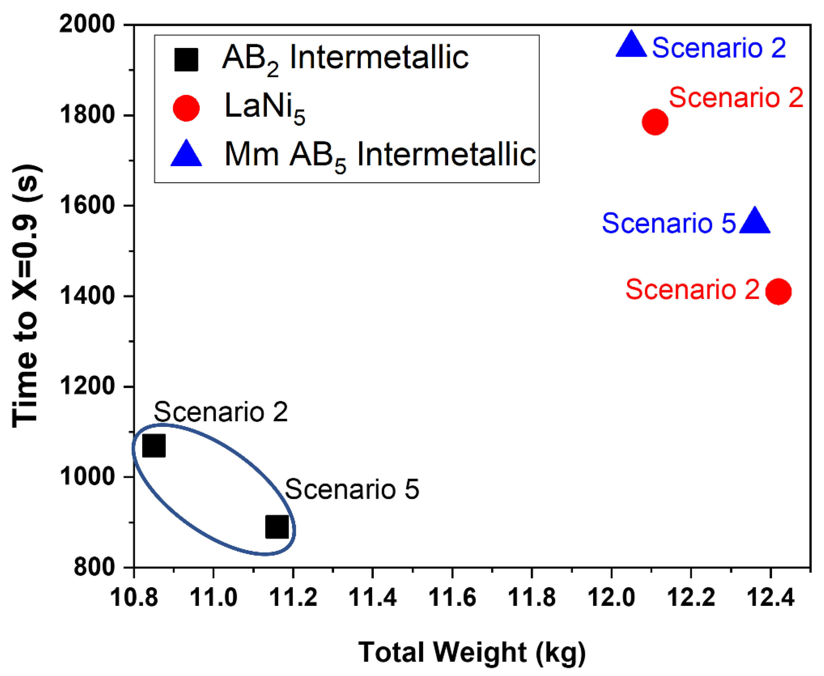
| N/A | AB2 Intermetallic ts (s) | LaNi5 ts (s) | Mm AB5 Intermetallic ts (s) |
|---|---|---|---|
| Scenario 1 | 1340 | 2051 | 2495 |
| Scenario 2 | 1070 | 1785 | 1950 |
| Scenario 3 | >2500 | >2500 | >2500 |
| Scenario 4 | 1250 | 1850 | 2179 |
| Scenario 5 | 890 | 1410 | 1560 |
| N/A | AB2 Intermetallic Total Mass (kg) | LaNi5 Total Mass (kg) | Mm AB5 Intermetallic Total Mass (kg) |
|---|---|---|---|
| Scenario 1 | 10.52 | 11.79 | 11.73 |
| Scenario 2 | 10.85 | 12.11 | 12.05 |
| Scenario 3 | 10.35 | 11.61 | 11.56 |
| Scenario 4 | 10.83 | 12.11 | 12.04 |
| Scenario 5 | 11.16 | 12.42 | 12.36 |
| Parameter | Unit | Value |
|---|---|---|
| Inner mass | kg | 175 |
| Block mass | kg | 175 |
| Head mass | kg | 67 |
| Fluid volume in fuel cell | L | 0.5 |
| Heat transfer area | m2 | 8 |
| Convective heat transfer coeff. | Wm−2K−1 | 1000 |
| Area for external convection to ambient | m2 | 1 |
| Convective heat transfer coeff. to ambient | Wm−2K−1 | 50 |
| Case | Cold Start Time (s) | Reduced Time (%) |
|---|---|---|
| No MH | 623 | 0 |
| AB2—Scenario 2 | 578 | 7.23 |
| AB2—Scenario 5 | 572 | 8.19 |
| LaNi5—Scenario 5 | 595 | 4.49 |
Publisher’s Note: MDPI stays neutral with regard to jurisdictional claims in published maps and institutional affiliations. |
© 2022 by the authors. Licensee MDPI, Basel, Switzerland. This article is an open access article distributed under the terms and conditions of the Creative Commons Attribution (CC BY) license (https://creativecommons.org/licenses/by/4.0/).
Share and Cite
Gkanas, E.I.; Wang, C.; Shepherd, S.; Curnick, O. Metal-Hydride-Based Hydrogen Storage as Potential Heat Source for the Cold Start of PEM FC in Hydrogen-Powered Coaches: A Comparative Study of Various Materials and Thermal Management Techniques. Hydrogen 2022, 3, 418-432. https://doi.org/10.3390/hydrogen3040026
Gkanas EI, Wang C, Shepherd S, Curnick O. Metal-Hydride-Based Hydrogen Storage as Potential Heat Source for the Cold Start of PEM FC in Hydrogen-Powered Coaches: A Comparative Study of Various Materials and Thermal Management Techniques. Hydrogen. 2022; 3(4):418-432. https://doi.org/10.3390/hydrogen3040026
Chicago/Turabian StyleGkanas, Evangelos I., Chongming Wang, Simon Shepherd, and Oliver Curnick. 2022. "Metal-Hydride-Based Hydrogen Storage as Potential Heat Source for the Cold Start of PEM FC in Hydrogen-Powered Coaches: A Comparative Study of Various Materials and Thermal Management Techniques" Hydrogen 3, no. 4: 418-432. https://doi.org/10.3390/hydrogen3040026
APA StyleGkanas, E. I., Wang, C., Shepherd, S., & Curnick, O. (2022). Metal-Hydride-Based Hydrogen Storage as Potential Heat Source for the Cold Start of PEM FC in Hydrogen-Powered Coaches: A Comparative Study of Various Materials and Thermal Management Techniques. Hydrogen, 3(4), 418-432. https://doi.org/10.3390/hydrogen3040026