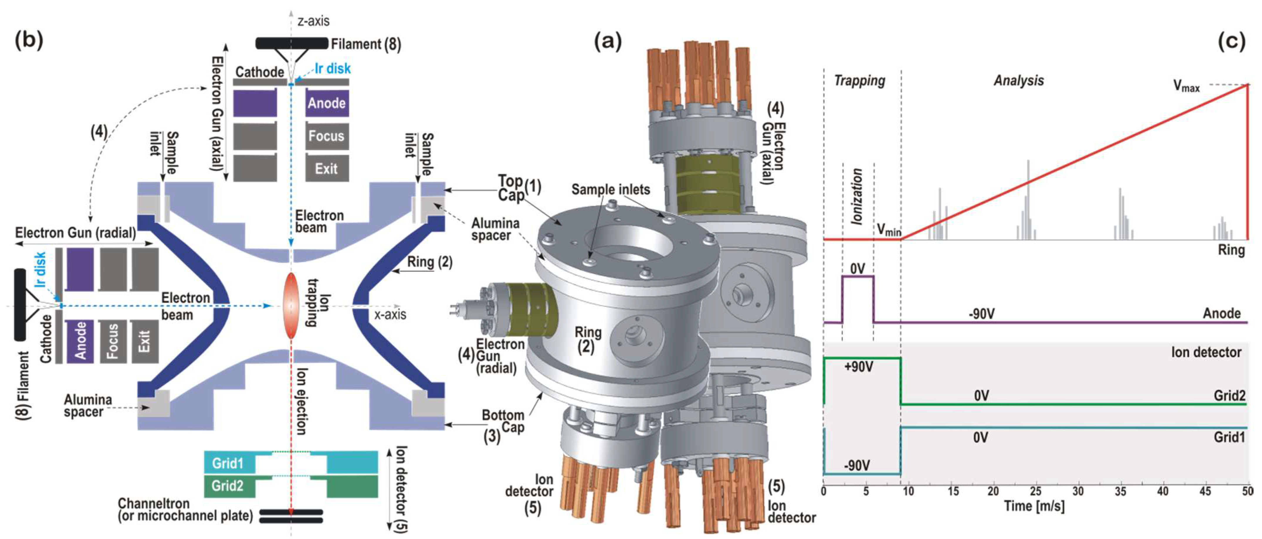
2.1. Sensor Design and Operation
The principle on which the QIT-MS sensor operates is illustrated in
Figure 1 and is that of a Paul ion trap using the time-dependent r.f. electric field. The ion confinement volume is defined by (1) top cap, (2) ring, and (3) bottom cap electrodes with hyperbolic interior surfaces. Electrodes are made of a Ti alloy, machined to within 0.0002” tolerance, and electrically insulated from each other with two alumina spacer rings. In this architecture, the QIT-MS sensor acts as a pressure cell because end cap (bottom and top) electrodes have a small hole along the central z-axis direction, and the ring electrode has four small holes along the radial x-axis direction. These holes serve as pumping apertures, inlets, and outlets for injecting the electron beam and the ejection of trapped ions. The samples to be analyzed are introduced into the trap through the holes in the top cap electrode and the alumina spacer ring. An additional crescent cut-out in the top cap electrode (see
Figure 2a, item 6) has been used in the experimental simulations [
8] of Enceladus plume flyby and served for the injection of hypervelocity water ice particles into the QIT-MS sensor.
The outer diameter of the end cap electrodes is 6 cm, and the compact design is preserved by running all electrical connections to the electrodes through mounting posts (see
Figure 1a). The electron gun assembly (4) has a filament (8) with a mounted iridium (Ir) disk as the electron emitter. Four electrodes (cathode, anode, focus, and exit) deliver the electron beam along the x-axis (radial ionization) or the z-axis (axial ionization) and focus it in the center of the trap. The Ir disk electron emitter is an equipotential planar surface that is an indirectly heated (by 1.55 A d.c.) point source with a low (~0.5 eV) energy spread of emitted electrons. The cathode is housed in the equipotential electrode (cathode holder), followed by a simple A/D = 1 three-electrode lens. The exit electrode has the same potential as the bottom cap electrode. The focus electrode defines the position of the cathode image inside the trap. By changing the potential of the focus electrode, the transmission of the electron beam through the ring or the top cap electrode can be optimized for the maximum ion production rate at a given filament current.
The ion detector assembly (5) consists of either the Channeltron or the z-stacked microchannel plates (shown) operated in a pulse counting mode at 2.5 kV, which integrates the charge from the plates into one output signal. The ion detector is placed in a holder such that the central axis of the collection area is aligned with the z-axis of the trap. In front of the ion detector are two repelling grids: one for electrons (Grid 1) and one for ions (Grid 2). Both grids are biased such that electrons and ions are unable to pass through to the detector during the ionization phase (when the anode is grounded) and are kept at ground potential during the analysis phase, as illustrated in
Figure 1c. Low mass cut-off and trapping properties are tuned with the trapping voltage V
min. In contrast, the mass range is set with the maximum ramping voltage V
max. In the nominal mode of operations, as shown in
Figure 1c, the QIT-MS sensor is operated with electrically grounded top cap and bottom cap electrodes. For the measurements of 98% concentrated sulfuric acid samples, the ring electrode is driven by V
min = 106 V and 882,832 Hz r.f. voltage with a 50 ms duty cycle (20 full mass spectra per second), and the maximum ejection voltage amplitude is V
max = 876 V. The duration of the ionization phase is shortened to 1.25 ms to reduce the protonation effects when operating at higher sulfuric acid vapor pressures (~5 × 10
−8 Torr) and prolonged to 8 ms to improve the counting statistics at lower sulfuric acid vapor pressures (~1 × 10
−9 Torr).
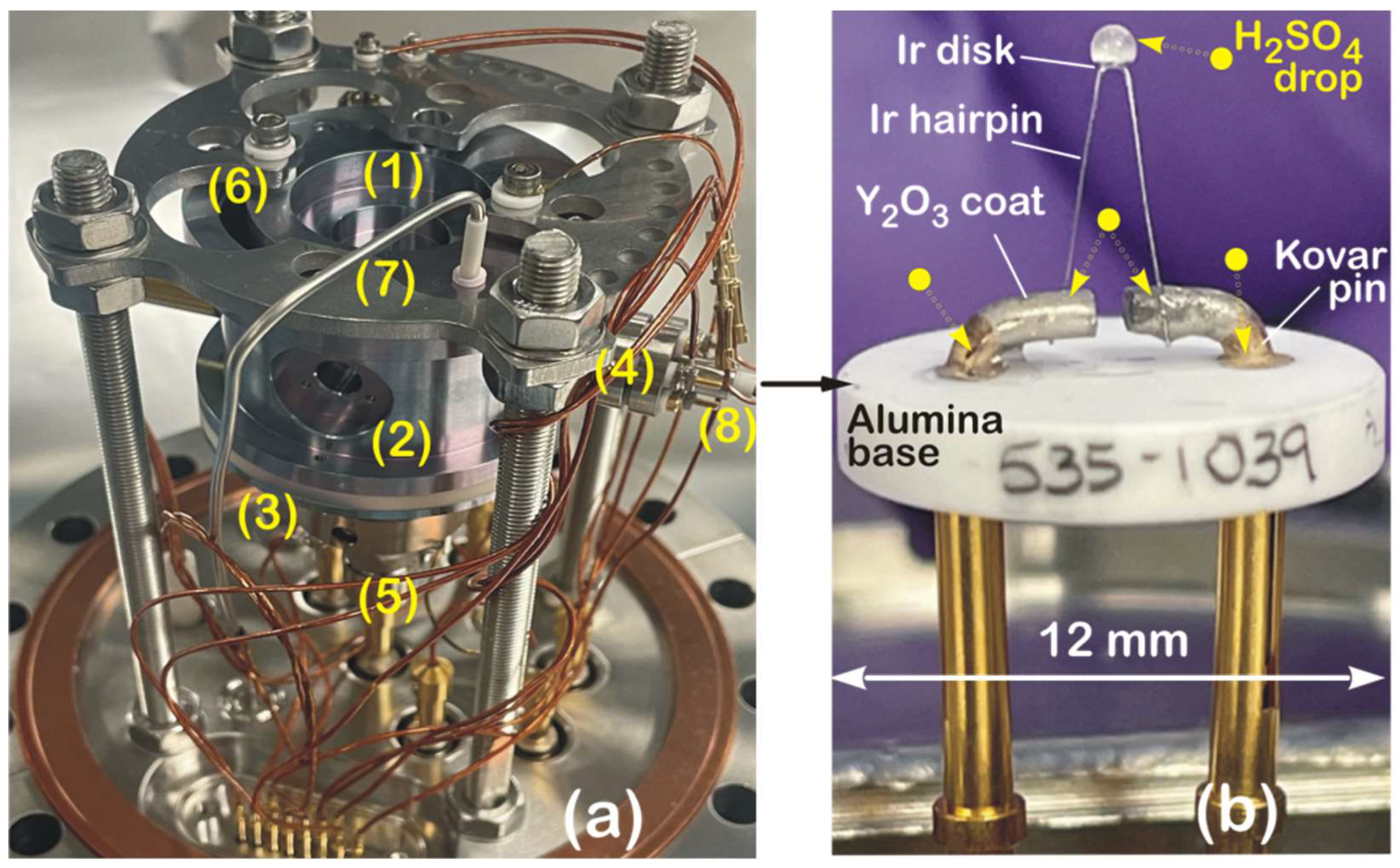
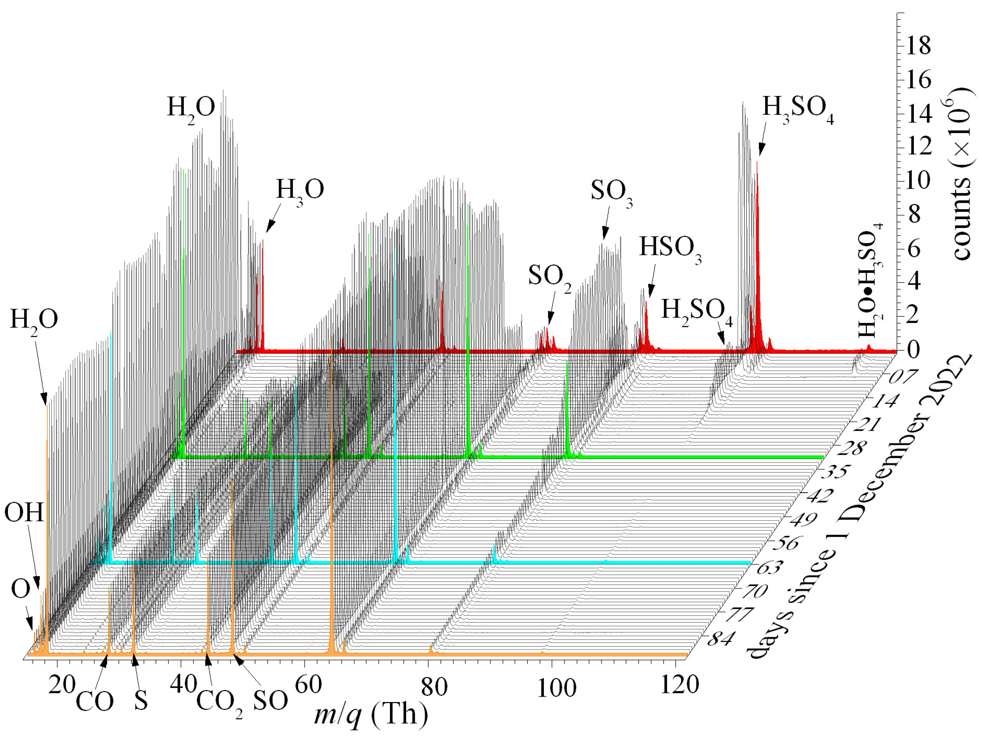
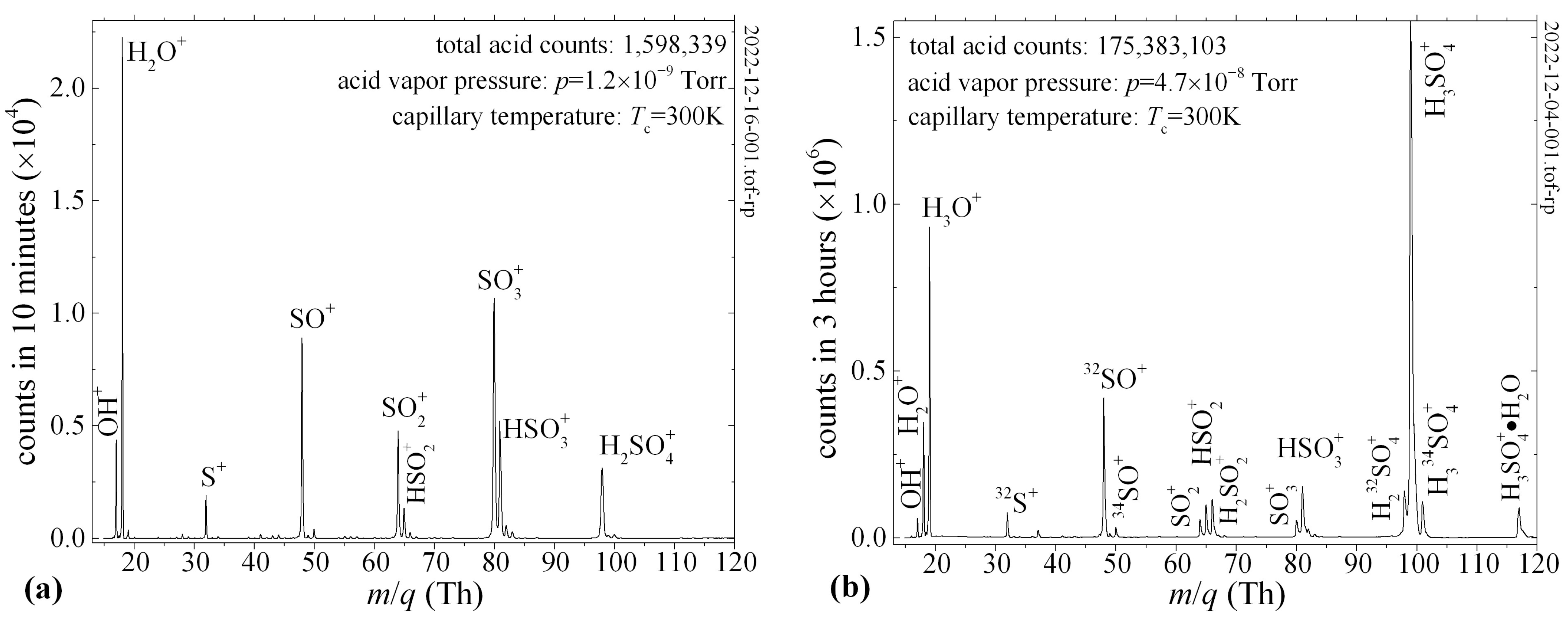
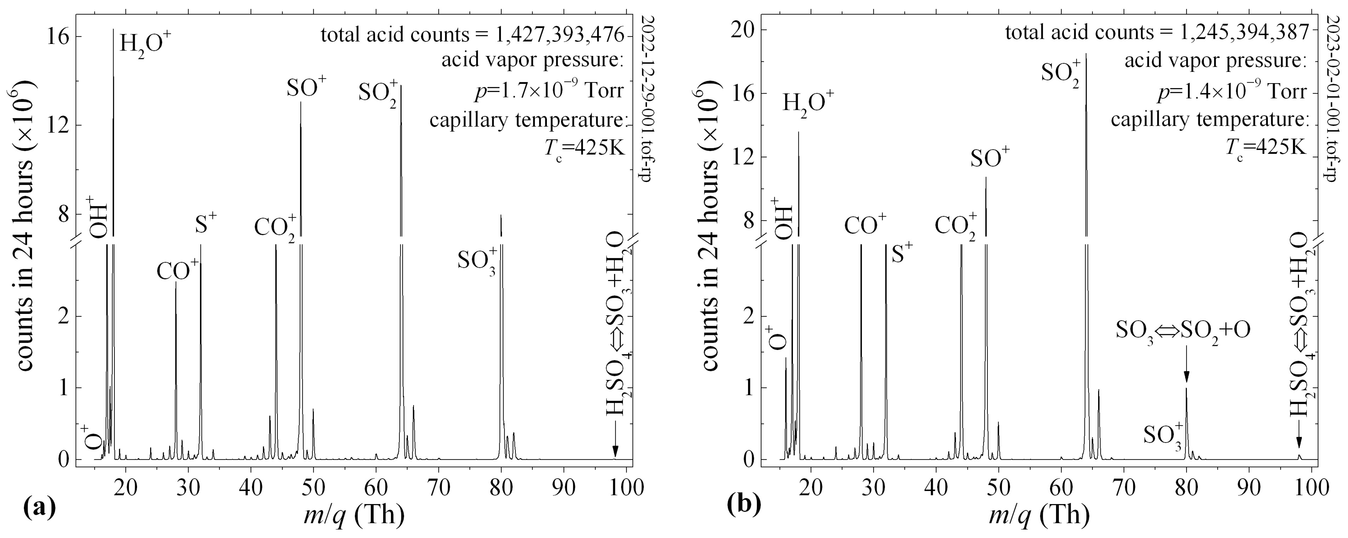
The QIT-MS sensor, shown in
Figure 2a, is rugged for continuous operations in sulfuric acid vapors, which is the most stressful test for the corrosive resistance of its components. For three months, starting on 1 December 2022, the QIT-MS sensor continuously acquired the mass spectra of the 98% concentrated sulfuric acid eluted into the ion trap via chemically inert capillaries. Shown are the QIT-MS sensor’s three electrically insulated electrodes: (1) the top cap, (2) ring, and (3) bottom cap; an electron gun assembly (4) in radial ionization configuration; and a Channeltron electron multiplier assembly (5) mounted on the bottom cap. The top cap has the crescent cut-out (6) previously used to inject microscopic water ice particles [
8]. The QIT-MS sensor was operated with electrically grounded top and bottom electrodes. The ring electrode was driven by a voltage scan function illustrated in
Figure 1c. The filament (8) of the electron gun assembly is detailed in
Figure 2b, and it consists of an yttrium oxide-coated iridium disk (ES-535 from Kimball Physics Inc., Wilton, NH, USA) that is heated by conduction from an iridium hairpin and mounted on an alumina insulator base. The filament was exposed to droplets of 98% concentrated H
2SO
4 and kept enclosed in the vacuum chamber under laboratory conditions for a month to allow for the corrosion of electrical contacts. The vacuum chamber was then evacuated to ultra-high vacuum (UHV), and the filament current was slowly ramped up to 1.45 A, yielding a normal operating temperature of 1200 K and 1–2 μA electron emission current. Repeated tests showed no functional damage to the Ir disk, Ir hairpins, or Kovar pins, confirming the corrosive resistance of the electron gun assembly to the sulfuric acid. The electrons emitted from the hot surface of the Ir disk were extracted as a 70 eV electron beam from the electron gun assembly, focused in the center of the ion trapping region (see
Figure 1b), and used for the ionization of sulfuric acid vapors.
We used the stainless steel tube (7) on the vacuum side to guide the 15 μm inner diameter chemically inert fused silica capillary into the QIT-MS sensor interior. Via the Valco fitting in the 6” ConFlat flange, the air side of a 60 cm long capillary was immersed in 98% concentrated liquid sulfuric acid. Liquid propagated through the capillary from atmospheric pressure into the QIT-MS sensor, where flash evaporation occurred in UHV. Acid vapors were electron impact-ionized during the first 9 ms of the duty cycle (see
Figure 1c), during which ion fragments were confined by driving the ring electrode with an RF voltage of constant amplitude V
min. By linearly ramping the ring electrode RF voltage amplitude during the 41 ms, confined ion fragments were subsequently ejected from the QIT-MS interior and detected by the Channeltron electron multiplier according to ion fragment mass-to-charge ratios (
m/
q). The results obtained are presented in
Section 3.
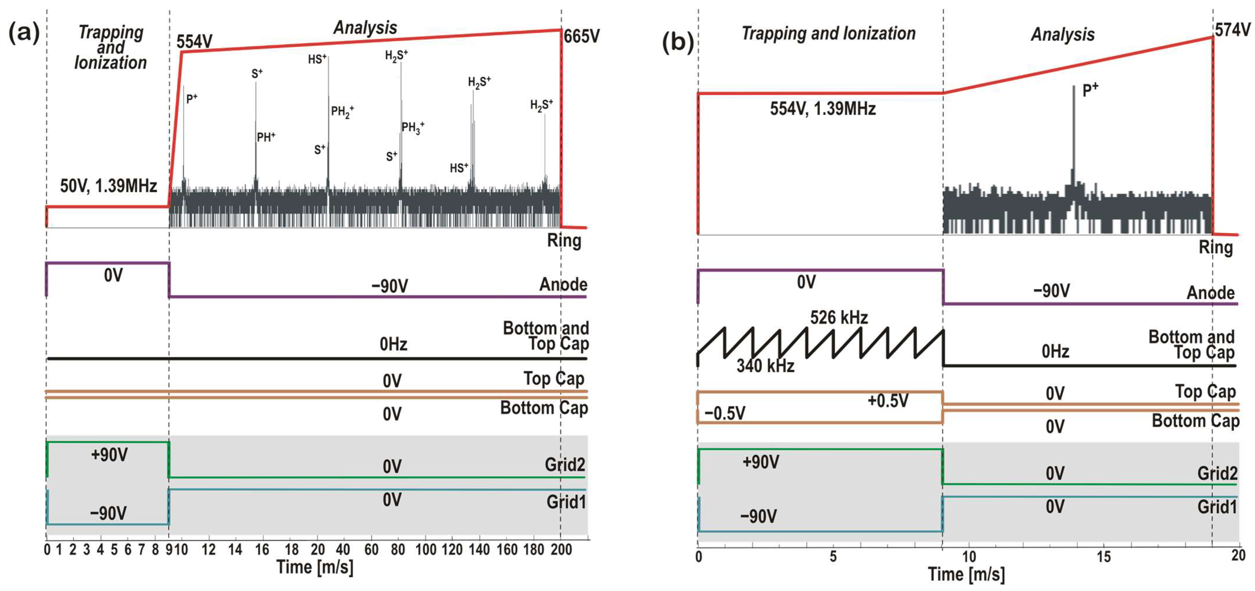
Two additional modes of operation of the QIT-MS sensor, both relevant to this study, are shown in
Figure 3. These are as follows: (a) the high-resolution low-sensitivity mode in
Figure 3a and (b) the low-resolution high-sensitivity mode in
Figure 3b. By slowing down the ring voltage ramp in
Figure 3a, we isolated the narrow mass range from
m/
q = 31 Th to
m/
q = 36 Th in the search for the parent (PH
3+, H
2S
+) and daughter ion fragments (P
+, S
+, PH
+, HS
+, PH
2+). We pulsed the grids the same way as in the study of H
2SO
4 (see
Figure 1c), with grounded top cap and bottom cap electrodes. The anode was pulsed during the 9 ms of the ionization phase at a higher filament current,
I = 1.48 A, to increase the overall ionization rate. The main differences in the PH
3 / H
2S study are the higher vacuum chamber pressure,
p = 7.1 × 10
−7 Torr, and slower voltage ramp function (190 ms analysis phase). The results for the high-resolution low-sensitivity mode will be published elsewhere.
On the other hand, the low-resolution, high-sensitivity secular mode proposed in
Figure 3b is designed to detect phosphorus species in Venus clouds. This particular mode of QIT-MS sensor operation was not used in this study, as both the top and bottom cap electrodes must be driven with a separate set of electronic boards. However, this mode was previously developed for collisional ionization studies at ~2 × 10
−5 Torr pressures and used in MS-MS operations of the QIT-MS sensor to detect nonvolatile organics on Ocean Worlds [
9]. One advantage of the secular mode is the enhanced signal from trace species (e.g., PH
3 and H
2S) concerning the dominant signal coming from one or more major species (e.g., CO
2 and N
2). Namely, higher operating pressures, longer ionization phases, and higher electron emission currents will proportionally produce more ions, the majority of which are CO
2+, and will obstruct the detection of trace ions, as illustrated in
Figure 4. If, during the ionization phase, both the top and bottom cap electrodes are driven with r.f. voltages composed of two or more secular frequencies, major species ions can be eliminated from the trap the instant they are created. Applied secular frequencies do not disturb the trapping of trace species that remain trapped and accumulated during the ionization phase and are detected in the analysis phase with increased precision.
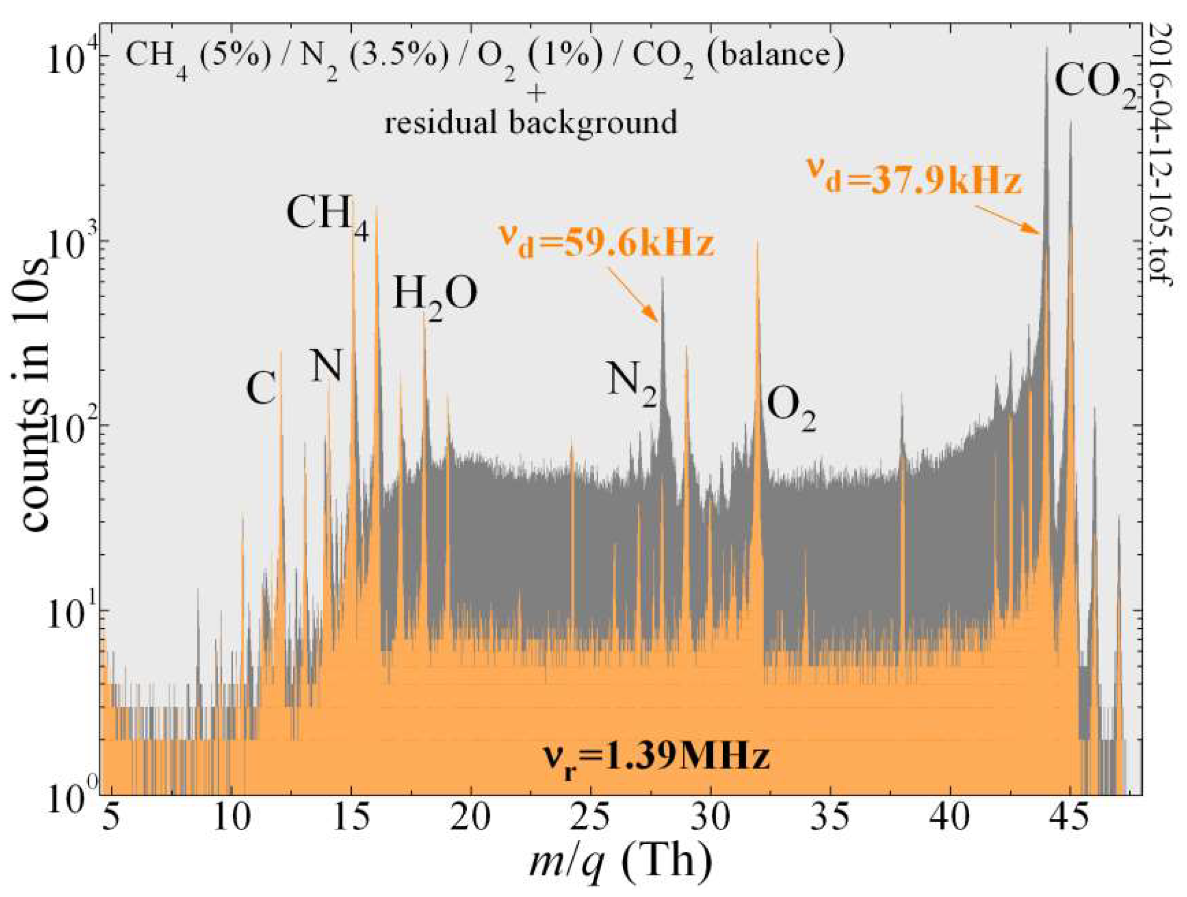
The dual-frequency secular mode illustrated in
Figure 4 demonstrates how the QIT-MS can detect trace gas components in the presence of major constituents CO
2 and N
2 when the pressure in the vacuum chamber was held at 4 × 10
−6 Torr. The mass spectrum obtained by the QIT-MS while operating in the “nominal” mode (with grounded end cap electrodes; see
Figure 1c) is given in a dark gray color. When operating in the “secular suppression” mode (orange color), a ~0.5 V auxiliary phase-inverted r.f. drive (similar to that in
Figure 3b) is used during the ionization phase to selectively suppress CO
2 and N
2 signals from the mass spectrum. The exception in this case is that instead of the frequency sweep, the superposition of specific secular frequencies (59.6 kHz and 37.9 kHz) was applied simultaneously to the end cap electrodes during the entire ionization phase. Notable reductions in the measured N
2 and CO
2 peak strengths (and their collision-induced low-mass tails) were achieved. The secular suppression of these two major species improved the signal-to-noise ratio of the trace species present in the residual gas background that are otherwise indistinguishable in CO
2 and N
2 low-mass tails. Because we suppressed dominant ion species during their creation, the space charge effects were also reduced, and we observed the improved trapping efficiency of residual gas background ions that the presence of CO
2+ and N
2+ ion clouds would otherwise cause them to become destabilized and prevent them from being efficiently trapped.
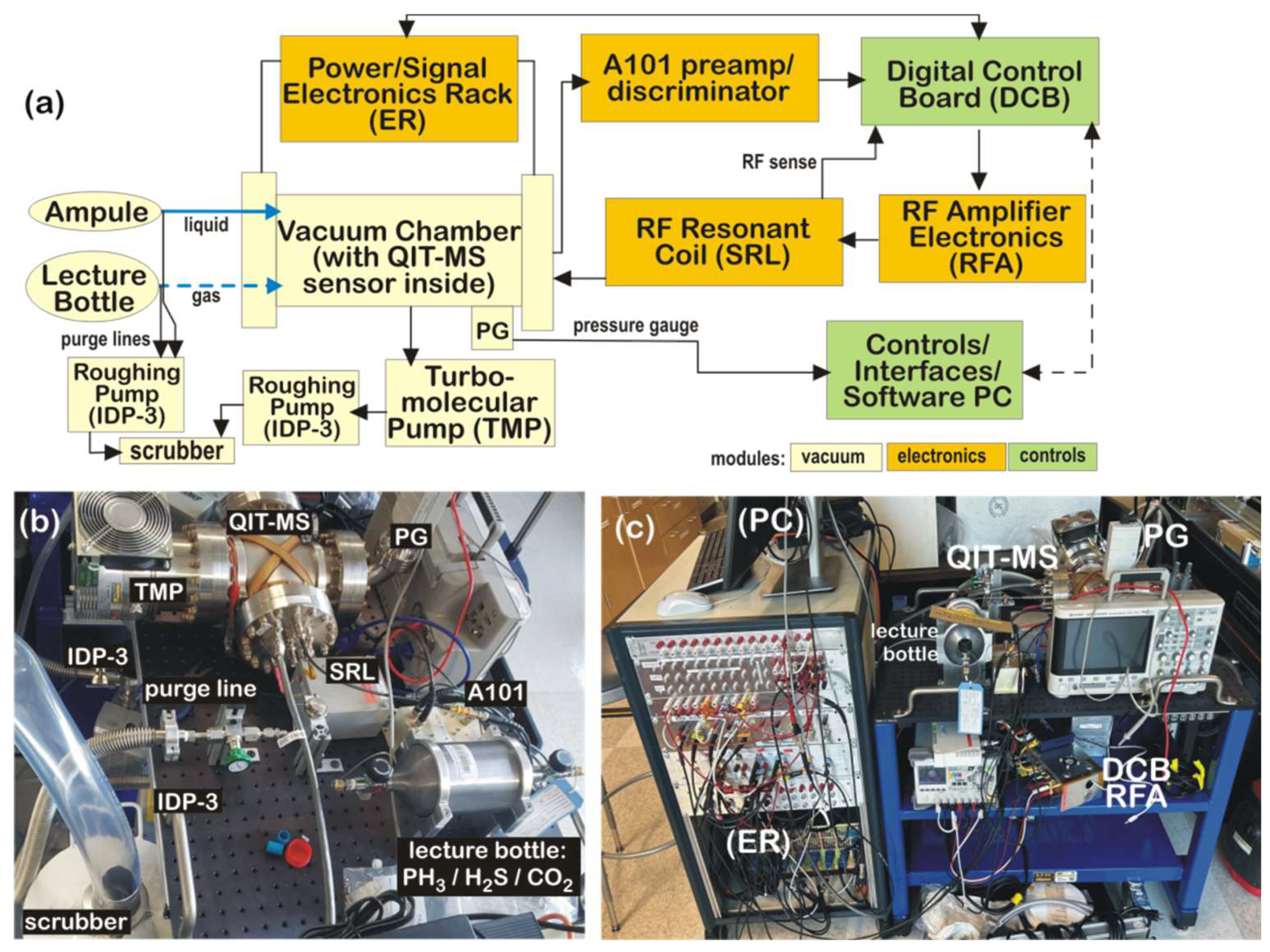
2.2. Testbed Setup
The experimental testbed contains three sets of hardware modules with components presented as a block diagram in
Figure 5a. The vacuum module consists of a vacuum chamber housing the QIT-MS sensor and supporting turbomolecular and roughing pumps.
The electronics module comprises custom boards to drive the top, bottom, and central ring electrodes of the QIT-MS sensor; power supplies; and pulsers as well as readout boards to monitor the quality of the RF drives and vacuum integrity. The control module consists of a custom Digital Control Board (DCB) with a dualcore ARM Cortex A9 (Arm Limited, San Jose, CA, USA) processor and the Xilinx Zynq 7010 (Advanced Micro Devices Inc, Santa Clara, CA, USA) Field-Programmable Gate Array (FPGA) system-on-chip logic that allows for firmware and hardware programming. The DCB runs on embedded Linux to remotely control all aspects of QIT-MS operations, instrument health telemetry, and the acquisition of mass spectrum data. These components are identified in
Figure 5b,c. Power/Signal supporting equipment is confined in the electronics rack (ER), which at the bottom has eight Kepco MST programmable power supplies in an RA 55 rack adapter (Kepco, Inc., Flushing, NY, USA) operated remotely via a GPIB controller (Kepco, Inc., Flushing, NY, USA). The next vertical component in the rack is the safety box, which monitors the pressure in the vacuum chamber. It turns off the Kepco power supply to the electron gun filament and shuts down the PHOTONIS high-voltage 3 kV feed to the ion detector (Channeltron/MAGNUM Electron Multiplier 5900 Series, Photonis Inc, Fiskdale, MA, USA). Above the safety box is a deck of National Instruments cards used to record signals in an analog manner. This is followed by a deck of voltage dividers, as well as a deck of counters, used to record ion detector signals via an Amptek A101 charge sensitive preamplifier/discriminator (Amptek Inc, Bedford, NH, USA) and a deck of pulsers used to drive the anode electrode in the Einzel lens of the electron gun assembly and protective grids in the ion detector assembly. The experimental setup has a remotely controlled oscilloscope for visualizing RF drives to QIT-MS electrodes and all pulser drives for the electron gun and detector assemblies. A PBR 260 Pirani/Bayard-Alpert gauge (PG, Pfeiffer Vacuum, Inc., Nashua, NY, USA) measures residual background pressure in the vacuum chamber. It is maintained at 5 × 10
−11 Torr by the turbomolecular pump (TMP, Agilent Technologies, Inc., Santa Clara, CA, USA) backed by the Agilent IDP-3 roughing pump. An RF tank (SRL) is inductively coupled to the QIT-MS sensor and resonantly amplifies the RF drive to the central electrode generated by the DCB and RFA. The SRL is a basket-weave of low-loss Litz wire on a 3D-printed polyetherimide mandrel (5.1 cm × 12.7 cm × 12.7 cm). The experimental testbed is controlled and operated by a Linux workstation (PC) using a suite of programs developed for QIT-MS operations, monitoring and controlling equipment, data acquisition, and analysis [
5].


