Article

A New Preclinical Surgical Model for the Assessment of Dental Implant Tissue Integration

1
Faculty of Dentistry, University of Toronto, Toronto, ON M5S 1G6, Canada
2
Institute of Biomedical Engineering, University of Toronto, Toronto, ON M5S 3G9, Canada
*
Author to whom correspondence should be addressed.
These authors contributed equally to this work.
Surgeries 2025, 6(2), 36; https://doi.org/10.3390/surgeries6020036
Submission received: 10 March 2025 / Revised: 3 April 2025 / Accepted: 14 April 2025 / Published: 17 April 2025

Abstract

:
Background/Objectives: The structural integrity and strength of the transgingival soft tissue seal around dental implant surfaces remain critical challenges. Therefore, animal models should include all three implant/tissue interfaces: bone, connective tissue, and epithelium. Thus, we sought to explore the rabbit mandibular diastema as a site for candidate intra-oral implant placement. Methods: Ninety-six custom mini-implants (with one of four different surfaces: machined, acid-etched, and with or without a nanotube coating) made from titanium 6/4 alloy were placed in the mandibular diastemas of twenty-four 16-week-old New Zealand white rabbits, with the implant collar above the alveolar crest. After 7, 21, and 42 days, the bony and connective tissue/implant interfaces were examined by light and scanning electron microscopy (SEM). Results: Of ninety-six implants, eight implants were found exposed to the oral cavity, with no evidence of soft tissue inflammation, suggesting that transmucosal implant placement would have been feasible. No significant differences were observed in collagen fiber orientation and fibrous tissue thickness by polarized light microscopy. However, SEM images showed that at all three time points, topographically complex nanotube surfaces had a profound effect on soft tissue peri-implant deposition, although functionally oriented collagen fibers were not identified attached to the implant surface. These surfaces also showed reparative peri-implant bone in the collar region. An intramembranous form of de novo bone formation was observed, together with tartrate-resistant acid-phosphatase-positive osteoclasts and multinucleate giant cells in the peri-implant endosseous compartment. Conclusions: Our results demonstrate that the rabbit mandibular diastema provides an intra-oral method of implant placement without the necessity of an extra-oral approach, tooth extractions, or bone augmentation procedures. Furthermore, given that three implant tissue interfaces can potentially be studied (bone, connective tissue, and epithelium) this model provides advantages over more traditional implant placement sites in the appendicular skeleton.

Graphical Abstract

1. Introduction

Titanium osseointegrated dental implants have proven to be a reliable treatment modality for replacing missing teeth, demonstrating success rates of over 90% after five to ten years of implant placement [1]. This success is owed, in part, to the extensive research in optimizing design to enhance the integration of bone with their modified surfaces, much of which has been carried out in preclinical animal studies. While many earlier works employed canine and mini-pig models, these species have become under increasing scrutiny and are censured in many jurisdictions, which has contributed to the increasing use of rodents and lagomorphs. We recently demonstrated that a novel rabbit mandibular diastema model could be used to study the osseointegration of titanium mini-screws of various surface topographies [2] and hypothesized that the model could be employed to examine peri-implant mucogingival tissues in addition to the peri-implant bone.
The rabbit mandible has been used by various authors as an implantation site, although the majority use invasive extra-oral surgical approaches [3,4,5], additional bone augmentation procedures [6,7,8], or the extraction of the anterior mandibular teeth to allow for the placement of implants with sizes more relevant to human application [9,10]. An exception is the intra-oral approach recently proposed by AlOtaibi et al. [11], who employed the extraction sockets of the rabbit secondary maxillary incisors as sites for implant placement. Nevertheless, a disadvantage of their approach is that the natural role of these secondary incisors, or “peg” teeth, to occlude against the lower mandibular incisors [12], limits the vertical dimension required to accommodate a transgingival component. Our mandibular diastema intra-oral approach demonstrated the feasibility of the anatomical location while obviating the need for invasive extra-oral surgery, tooth extractions, or bone augmentation.
A unique feature of dental implants, compared to orthopedic endosseous implants, is the presence of a transmucosal component that traverses soft tissue into the bacteria-laden oral cavity. While alveolar bone provides mechanical anchorage for dental implants, it is the connective tissue and epithelium of the gingival mucosa that serve as the biological barrier that separates the distinct internal tissue from the external oral environment [13]. This mucogingival barrier is critically important in preventing the ingress and accumulation of pathogenic oral bacteria that, if breached, can lead to peri-implant complications [14,15,16]. The clinical prevalence of these complications remains high, with peri-implant mucositis and peri-implantitis being estimated to occur in 43% and 22% of cases, respectively [17]. For this reason, orthopedic models—typically femoral or tibial implant placements—reproduce only one of the three tissue interfaces (bone) of critical importance for dental implants.
An additional advantage is that the rabbit mandibular diastema exhibits minimal growth after four months of age [18], reaches early skeletal maturity [19], and allows for a stable implant position even after 85 days of placement [2]. This contrasts with transcortical femoral and tibial orthopedic implant placement in young rodents, where continuing growth results in virtual implant drift over longer experimental periods [20].
Thus, we hypothesized that the rabbit mandibular diastema could be used as a site for candidate intra-oral implant placement. Herein, we describe the detailed surgical procedure of our rabbit mandibular diastema model and illustrate the influence of implant surface topography on both the implant/bone and implant/connective tissue interfaces. After placement, some implants become exposed to the oral cavity without causing noticeable masticatory issues or tissue inflammation. This provides strong evidence that the model could be used in the future to study the implant/epithelial interface. Furthermore, we illustrate the presence of both multinucleate giant cells (MNGCs) and osteoclasts on the implant and bone surfaces, respectively, the histochemical staining of which we deal with in more detail elsewhere [21].

2. Materials and Methods

2.1. Experimental Design

Ethics approval was received from the Health Sciences Local Animal Care Committee, Faculty of Medicine, University of Toronto (Protocol #20012429; approved 14 September 2019) prior to the experiment. A pilot study [2] was employed to develop the method [Original Protocol #: 20012182; 26 April 2019] with subsequent modifications, as reported in detail in [22]. Rabbits were sourced from Charles River Laboratories, Senneville, QC, Canada, and singly housed at 21 °C in conventional caging provided with corn cob bedding and a 12 h light/dark cycle. Reporting followed ARRIVE guidelines.
Briefly, 96 custom-made mini-implants made from titanium 6/4 alloy of 2 mm diameter and 3 mm length (Figure 1), with cover screws, were kindly supplied by Zimmer Biomet Dental (now ZimVie, Palm Beach Gardens, FL, USA) and implanted in 24 sixteen-week-old New Zealand white rabbits, with the implant collar above the alveolar crest. Four different surfaces were created as follows: (1) machined (M), (2) machined surface with nanotubes (MN), (3) dual-acid-etched (DAE), and (4) dual-acid-etched with nanotubes (DAEN). The M and DAE surfaces were chosen to represent the most commonly used surfaces in dental implants (acid-etched titanium/alloy with or without prior sandblasting) [23]. However, we and others have shown that adding nano-topographic surface complexity can accelerate early endosseous healing [24] and influence biofilm formation [25]. Thus, both surfaces were modified with a nanotube coating after cleaning with ultrasonication in concentrated detergent and rinsing in de-ionized water to create the MN and DAEN groups. These implants were anodized in an electrolyte consisting of 0.25 wt% hydrofluoric acid. The titanium implant anode and a cpTi cathode were connected to a power supply (BK Precision 9602) at 20 V and immersed in the electrolyte solution at room temperature for 30 min. After anodization, the implants were rinsed in de-ionized water and dried at 120 °C for 1 h.
The cover screws were also modified to have the corresponding surface type. The implants and cover screws were sterilized using gamma irradiation at a standard dose of 25 KGy. Two implants were placed in each mandibular diastema of the rabbits weighing approximately 3.0 kg using the Latin square model, such that each implant type appeared once per animal.

2.2. Scanning Electron Microscopy

Field emission scanning electron microscopy was performed at the Centre for Nanostructure Imaging, University of Toronto. The implants were carbon-sputter-coated, and high-resolution photomicrographs of different areas of each implant were taken using a Hitachi S-5200 scanning electron microscope. The implant surfaces were mapped (4 areas: 144 μm × 108 μm) using a Keyence microscope (VK-X1050and analyzed with MultiFile Analyzer (Keyence Corp, Itasca, IL, USA) to derive surface roughness (Sa) values.

2.3. Animal Model

The adult rabbit mandibular diastema is an edentulous region between the incisor and the first premolar, which is approximately 23 mm long and 3 mm wide at its crest. The bone that lies above the curved incisor is, at its maximum height, about 4–6 mm in the apico-coronal dimension depending on the age of the rabbit. This region contains a circumferential cortex surrounding cancellous bone except at the mandibular symphysis. The height from the superior portion of the incisor’s periodontal ligament to the crest varies throughout the length of the diastema due to the curvature of the lower incisor. An antero-posterior span limited to 11–16 mm from the mesial alveolar crest of the mandibular first premolar avoids the anterior opening of the mental foramen located in the distal third of the mandibular diastema [2]. Therefore, two submerged 2 × 3 mm dental implants could be safely placed within the mandibular diastema.

2.4. Anesthesia and Pre-Surgical Preparation

General anesthesia was administered by an intramuscular infiltration of ketamine 35 mg/kg and xylazine 5 mg/kg, followed by inhalation of isoflurane at 1–3% for maintenance using a modified v-gel supraglottic airway device in which the lateral flanges were removed to facilitate access to the oral cavity. Pulse oximetry, heart rate, respiratory rate, and intermittent toe pinches were used to monitor the level of anesthesia throughout the surgery. For analgesia, sustained-release buprenorphine 0.12 mg/kg was administered once subcutaneously (SC) prior to surgery, and 1 mg/kg of meloxicam was administered SC once a day for 3 days postoperatively. To reduce the risk of infection, enrofloxacine 5 mg/kg was administered subcutaneously at the time of surgery. Chlorhexidine (0.12%) was used to clean the peri-oral cavity. Bilateral mental blocks were administered using 2% Lidocaine with 1:100,000 epinephrine, using a dental syringe and a 30-gauge short needle. Surgery was performed on one side of the mandible at a time with the aid of surgical loupes (3.8× magnification) and lights. All intra-oral preparation and implant surgeries were performed by the same operator (RN).

2.5. Surgical Procedure

The surgical procedure is shown in Figure 2, while Figure 3 illustrates the detailed process and implant placement.
Once anesthesia was achieved, the oral cavity was maintained in the open position using a rabbit tabletop mouth gag (IM3, Vancouver, WA, USA), and a 2.0 cm oblique incision was made intra-orally on the buccal mucosa lateral to the diastema (between the central incisor and the first premolar) and anterior to the mental foramen identified by palpation (Figure 3A). A second oblique incision connected the initial incision to the mandibular crest, allowing a triangular split-thickness flap to be raised to expose the underlying connective tissue and muscle. Then, a full-thickness vertical incision was made along the length of the diastema, followed by a full exposure of the underlying bony crest by blunt dissection (Figure 3B). All attached keratinized tissue, oral mucosa, underlying muscle, and periosteum were detached from the mandibular crest. Using a periodontal probe and a graphite (“lead”) pencil, two pre-osteotomy markings were made on the surface of the bone 11 mm and 16.5 mm anterior to the base of the first premolar (Figure 3E). A unicortical drill hole was generated to the marrow cavity using a round-tip carbide dental bur (twist drill 1.3 mm diameter, Brasseler Canada, Québec City, QC, Canada) at the first marking (Figure 3F). An osteotomy of 2 mm × 3 mm was then performed using a specially designed quad-shaping drill bit (Figure 1B) with a stop to ensure the bit went to the precise depth required (Figure 3G). The implants were inserted so the cover screw and first thread were exposed to the gingival connective tissue. Drilling was achieved at a speed of 1200 RPM using a handpiece mounted on an electric motor (WI-75 LED-G and BIOMET 3i DU1000, respectively Biomet 3i, Palm Beach Gardens, FL, USA). Saline irrigation and suction were maintained throughout the drilling sequence to avoid overheating and to remove bony debris. A second osteotomy site was then prepared at the second marked location, as described above. Each osteotomy site received a 2 mm × 3 mm mini-threaded implant and a corresponding cover screw, which were inserted using an implant driver (Figure 2D and Figure 3H,I). The site was then irrigated again to remove debris. Three biodegradable interrupted sutures were used to obtain primary closure of the wound (Figure 3D—note that the implant cover screws were clearly visible beneath the overlying mucosa—Figure 2F). Once hemostasis was confirmed, surgery on the contralateral diastema was conducted, as described above.

2.6. Euthanasia

The rabbits were euthanized, following anesthesia with 1–3% of isoflurane, after one of three implantation periods of 7, 21, or 42 days, using an injectable solution of embutramide, mebozonium iodide, and tetracaine hydrochloride (0.3 mL/kg of T-61). Upon sacrifice, the mandibles were dissected and split along the mandibular symphysis to produce two hemi-mandibles, each with two mini-threaded implants.

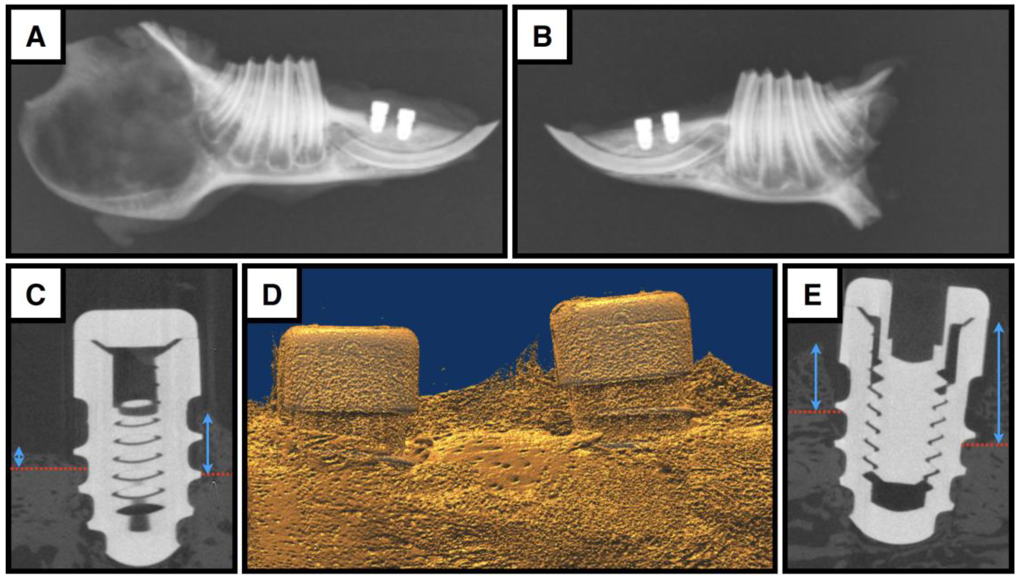
2.7. X-Ray and microCT Analysis

Radiographs for all hemi-mandibles were obtained after harvesting to visualize the implant placement and areas of peri-implant bone loss/formation. Based on these radiographs, some samples were further analyzed using high-resolution micro-computed tomography (Phoenix v|tome|x micro-CT). These specimens were trimmed to a length of 2 cm, and soft tissues surrounding the two implants were left undisturbed. Final scan resolutions were recorded at 12 nm.

2.8. Sample Harvesting

One cadaveric hemi-mandible sample from a 4-month-old rabbit, in addition to the experimental cohorts mentioned above, was prepared for routine decalcified hematoxylin-and-eosin-stained histology to image the normal histological anatomy of the relevant surgical area. This sample was fixed in formalin, decalcified in 12% formic acid for 14 days, dehydrated in an ethanol series, embedded in paraffin, and sectioned in the coronal plane at a thickness of 6 microns before staining [2].
The hemi-mandibles destined for nondecalcified histologic analysis had the excess lateral and medial soft tissues trimmed, leaving that above the implants undisturbed, following which they were immediately fixed at 4 °C in paraformaldehyde (4%) for 72 hrs. Excess mandibular bone was removed using a diamond saw (EXAKT 300, Cutting and Grinding System, Oklahoma City, OK, USA), and the trimmed samples were stored in phosphate-buffered saline at 4 °C until further processing, at which time they were washed in running water for 1 h before dehydration.
The hemi-mandibles destined for SEM imaging had the soft tissues covering the implant cover screws gently reflected and fixed in place with sutures before fixation to enable visualization of the soft tissue/implant interface. These samples were immediately placed into freshly prepared Karnovsky solution (8% paraformaldehyde, 25% glutaraldehyde, 0.2 M cacodylate buffer) until further processing. After dehydration, the samples were critical-point-dried (Bal-Tec SPD 030 Critical Point Dryer Baltec Los Angeles, CA, USA), mounted to aluminum stubs, and then gold-sputter-coated (Denton Desk II sputter coater, Denton Moorestown, NJ, USA) before being viewed by scanning electron microscopy at the Centre for Nanostructure Imaging, Department of Chemistry, University of Toronto. A large-stage environmental SEM (FEI Quanta FEG 250, Thermo Fisher Scietific Mississauga, ON, USA) with a BF/DF STEM detector was used at 5–15 kEV with a working distance of 10 mm.

2.9. Sample Processing for Resin Embedding

One of two resin-embedding systems was used to produce undecalcified ground sections with metallic implants in situ: either (1) an Osteo-Bed Bone Embedding Kit (Polysciences, Warrington, PA, USA) or (2) a Technovit 9100 MMA Embedding Kit (“TKit” Heraeus Kulzer, Germany). For both methods, following fixation, the samples were dehydrated in ethanol according to the following protocol: 70% twice for 1 h, 80% twice for 1 h, 90% three times for 1 h, 95% twice for 1 h, 100% three times for 1 h, and 100% once overnight. Once dehydrated, the samples were defatted in one change of xylene for 1 h and were rinsed in 100% ethanol three times for 1 h to remove excess xylene.

2.9.1. Osteobed Method

The defatted samples were embedded using an Osteo-Bed Bone Embedding Kit (Polysciences) by initial immersion in PMMA for 3 days (with one change the first two days) and then in a solution of PMMA with 1.4% benzoyl peroxide for another two days under vacuum at room temperature (with one change the first day). An embedding solution consisting of 3.5% benzoyl peroxide was prepared and poured onto the specimens placed in scintillation vials. The embedding process was completed with polymerization of the solution under vacuum in a dry oven at 45 °C for at least 2 days.

2.9.2. Technovit Method

Samples were defatted in xylene for a second time and then infiltrated with a series of methyl methacrylate solutions according to the five-step protocol provided by the TKit over 6 days. Technovit 9100 (Fisher Scientific, Ottawa, ON, Canada). Basis solution was destabilized through a chromatography column filled with aluminum oxide (active, basic, 90), which was then used in combination with different concentrations of PMMA powder, hardeners, and a polymerization regulator to produce pre-infiltration, infiltration, and polymerization solutions, as outlined in Table 1. All pre-infiltration and infiltration steps were completed at 4 °C under vacuum. The final polymerization mixture was poured over the samples that were positioned in pre-cooled −20 °C vials. To remove oxygen during the final polymerization process, uncapped samples were placed in a gassing chamber, vacuumed for 20 min, and then gassed with carbon dioxide for an additional 20 min before being left to polymerize for 3 days at −20 °C.

2.10. Histological Sectioning

The vials were broken at the end of the polymerization process, and the resin blocks were trimmed into smaller rectangular blocks. Using the two cover screws as a reference, excess resin on all four sides of the hemi-mandible were removed.
Both longitudinal and transverse blocks were prepared.
For the longitudinal blocks, methyl methacrylate-based glue (Technovit 7210 VLC, Heraeus Kulzer, Germany) was applied to the under surface of the block, which was then adhered to an acrylic slide to orient the implants vertically. The block was then bisected, using a diamond saw (EXAKT 300), after a guideline was drawn with a pencil down the center plane of the cover screws of both implants. The halved blocks revealed each implant in a longitudinal section with comparable diameters and thickness.
The cut surfaces of each block were ground using 320 grit sandpaper (Buelhler Ecomet III Polisher, Lake Bluff, IL, USA) before being adhered to a final acrylic slide using Technovit 7210 VLCl. The blocks were lightly coated with toluene (Caledon Laboratories, Georgetown, ON, Canada) prior to applying the adhesive to eliminate trapped air bubbles. Once the adhesive was applied, the sections were mounted using an EXAKT 402 Precision Adhesive Press and cured under UV light for 10 min.
For the transverse implant sections, bisected blocks were prepared such that the cover screws of each implant were aligned parallel to the cutting plane. To adhere sections to acrylic slides, the same protocol was followed, as described above. Once cured, the acrylic slides were mounted onto the EXAKT cutting system, and the tissue block was sectioned at a distance of 200 μm from the slide. The slides were then polished with decreasing paper grit (320, 400, 600, 1200, 2400, 4000, Buehler, USA) until a thickness of about 50 μm was reached.
Using the protocol described above, serial sections were produced from the remaining sectioned blocks to comprise the full thickness of each implant. Each block yielded, on average, 1–3 slides.

2.10.1. Staining of Osteobed Sections

Staining was accomplished with a solution of 0.3% toluidine blue heated to 50 °C for two minutes. The staining solution was deposited on the surface of the specimen with an eye dropper until fully immersed. The slides were immediately rinsed with distilled water, wiped down with 70% ethanol and 100% ethanol, and then dried for 10 min at room temperature. The slides were counterstained with a 0.3% solution of Light Green SF Yellowish (Millipore Sigma, Oakville, ON, Canada) in 2% acetic acid for three minutes at room temperature. The slides were wiped down with 100% ethanol, dried at room temperature, and mounted with 100% ethanol and a coverslip immediately prior to imaging. Histological observations were made using Leitz Diaplan and Aristoplan microscopes (Leica, Germany), each fitted with a digital camera (Zeiss Axiocam ICc 5, Oberkochen, Germany; AmScope MA500, North York, ON, Canada) and coupled to imaging software (Zeiss Zen 2.3 lite, Germany). To observe the birefringent nature of the collagen fibers, the slides were similarly imaged under added polarized and lambda filters to produce polarized light photomicrographs.

2.10.2. Staining of Technovit Sections

The surfaces of each slide were deplasticized in two changes of 4% hydrogen peroxide (5 min each) and rehydrated in a series of ethanol concentrations according to the following protocol: 100% three times for 2 min, 95% twice for 2 min, 70% twice for 2 min, and twice in distilled water for 2 min each. To ensure the adequate removal of resin from the surfaces, the slides were placed in 0.1 M acetate buffer (pH 5.0) twice for 5 min.
TRAP staining. Using a TRAP Staining Kit (Sigma Aldrich, Oakville, ON, Canada), the solutions were prepared according to Table 2. The TRAP Staining Solution Mix was placed in a staining dish and pre-warmed to 37 °C in a water bath. Deplasticized and rehydrated slides were then placed in the pre-warmed TRAP Staining Solution Mix, incubated at 37 °C for 1 h, and thoroughly rinsed in 3 changes of distilled water.
Hematoxylin counter-staining. The TRAP-stained slides were counterstained with Harris Modified Hematoxylin (Cedarlane, Burlington, ON, Canada) for 30 min. The slides were washed in three changes of tap water, dipped once in 1% Acid Alcohol (Cedarlane, Canada) for differentiation, and rinsed again in three changes of tap water. The hematoxylin was blued in Scott Tap Water Substitute (Cedarlane, Canada) for 30 min, washed in three changes of tap water, and rinsed in distilled water. Excess water was drained from the slides, which were then dipped in 70% ethanol ten times and left to dry at room temperature. The slides were coverslipped with 100% ethanol prior to imaging.
Quantitative analysis. The TRAP staining intensity of both mono- and multinucleate cell subtypes was determined as described in detail elsewhere [21].

3. Results

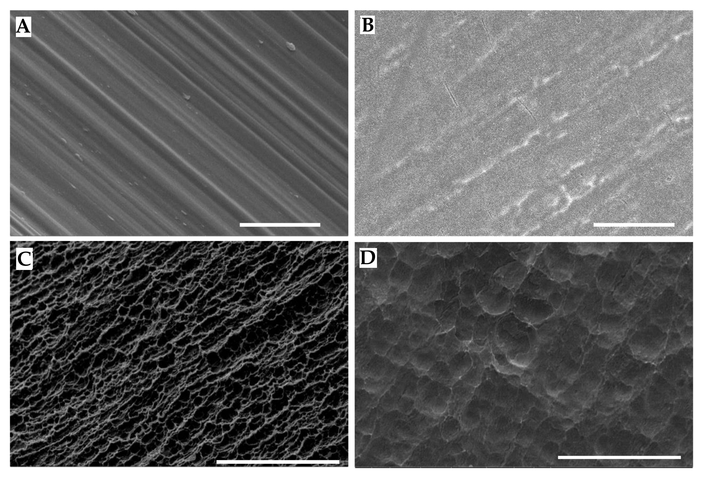
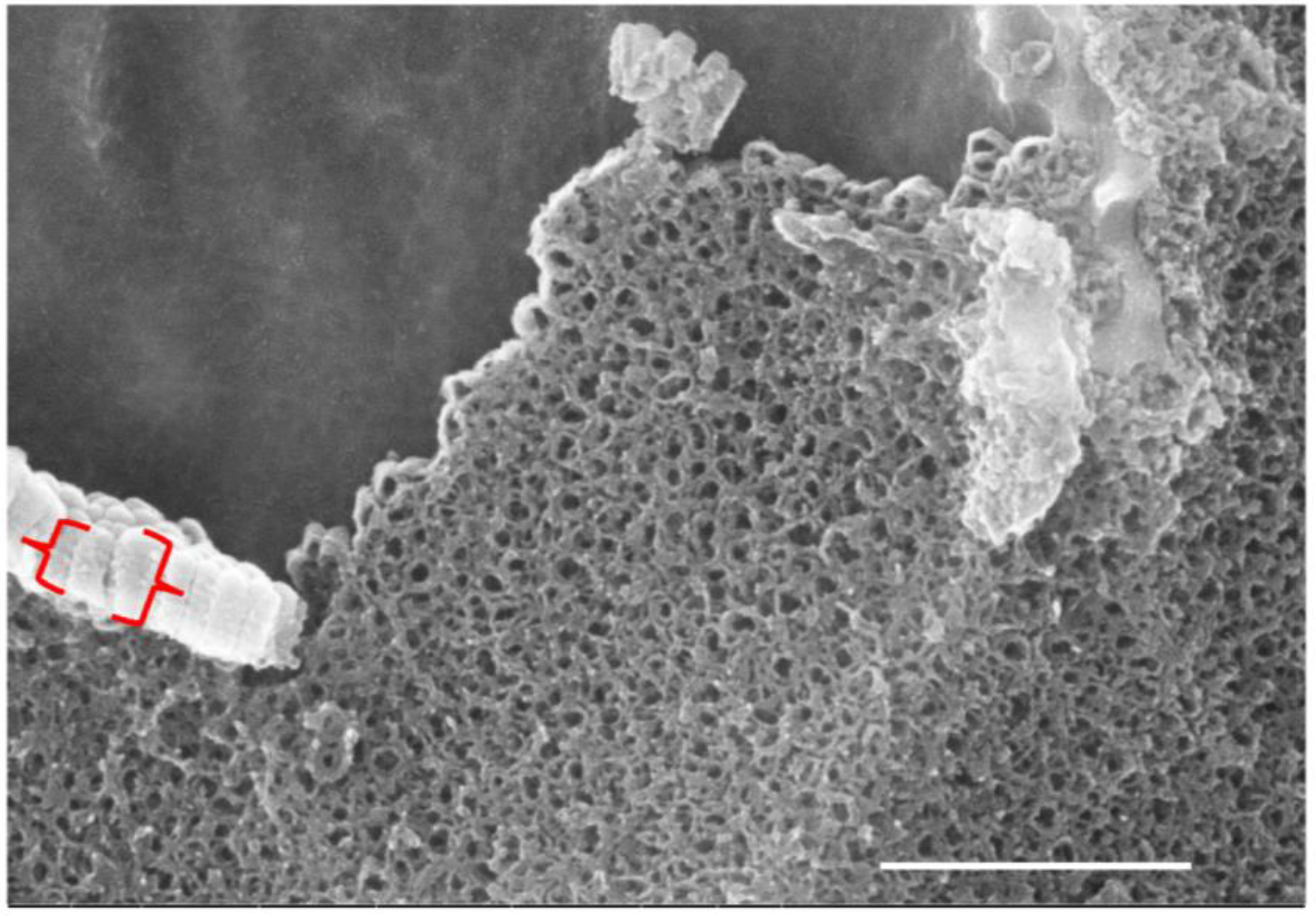
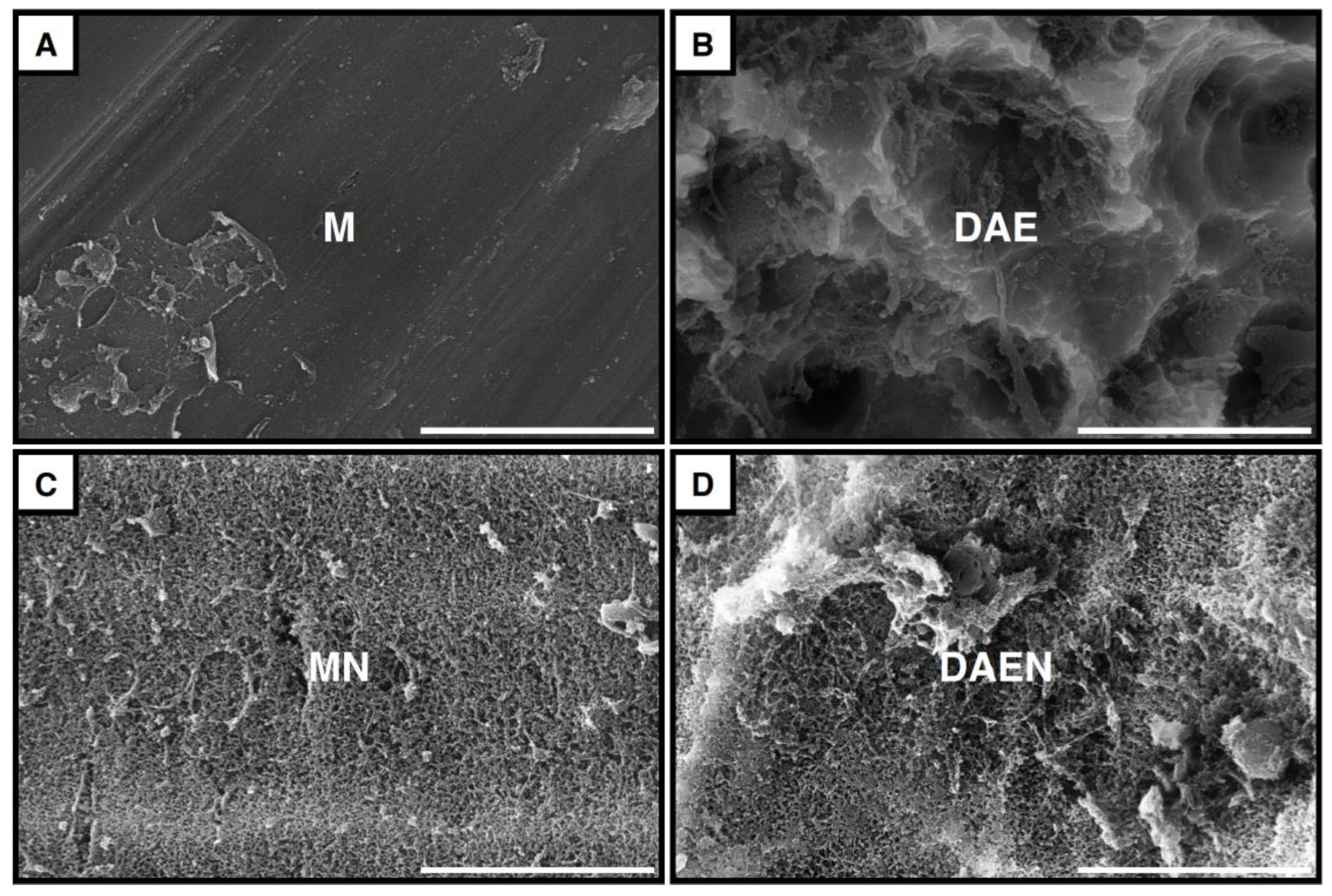
3.1. Implant Surfaces

Micrographs of the four different implant surfaces are shown in Figure 4. At low magnification (Figure 4A–D), the machined and acid-etched implants showed rather homogenous surfaces, but, as expected, pronounced differences in morphology and topography became apparent as the magnification was increased. While these differences were not statistically different using the Keyence optical microscope output (for example, four reading averages of 0.33925 μm and 0.313424 μm for M and DAEN, respectively), the SEM images showed obvious differences. The machined (M) surfaces showed the expected unidirectional machining ridges and grooves, which were somewhat less evident in the machined nanotube (MN) surface due to the thicker overlying oxide layer of nanotubes with pore diameters in the 70–100 nm scale range. The dual-acid-etched (DAE) surface, in comparison, showed significant surface roughness, with a pronounced distribution of small peaks and divots with dimensions in the low micron range, which were similarly diminished in scale in the DAEN samples due to the oxide nanotube coating. The latter was more obvious where it had been fractured and peeled away from the underlying acid-etched surface (Figure 5). In these areas, the nanotube layer was 220–290 nm thick.

3.2. Surgical Outcomes

All 24 rabbits survived the surgical procedure without intraoperative complications. The primary stability of the implants and wound closure by primary intent were confirmed for all the animals. Postoperative recovery was uneventful, and all the animals maintained good health until the day of euthanasia. The first forty-eight implants were inserted with an inter-implant distance of 5.5 mm (based on our cadaveric study where we completely submerged the implants), but an examination of the initial radiographic images revealed no evidence of implant encroachment of the mandibular incisors. Thus, for the remaining 48 implants, the anterior osteotomy was moved anteriorly 0.5 mm to increase the inter-implant distance to 6 mm.
One implant on Day 7, one implant on Day 21, and six implants on Day 72 were exposed to the oral cavity at the time of sacrifice without a predilection to a specific surface type (Figure 6). In two animals, both the ipsilateral mesial and distal implants were prematurely exposed. In these cases, a mass of debris and hair was found wedged between and around the implant heads. In all eight cases, a peri-implant sulcus had formed surrounding the implant. Furthermore, none of the exposed implants showed any signs of mobility, erythema, edema, or suppuration upon palpation, while the remaining eighty-eight implants healed with complete wound closure without any sign of infection or soft tissue deformity at the surgical site.
The mucogingival tissue of the rabbit mandibular diastema contains salivary and fat tissue in addition to the muscle attachment of the buccinator that crosses the alveolus to insert in the lingual mandibular ridge, as illustrated in the cadaveric histology in Figure 6B–D. The surgical procedure severed the connection of the buccinator, reduced the lingual alveolar ridge, and displaced the fat and salivary tissue buccally to permit implant site preparation.

3.3. The Bony Compartment

In most cases, considerable peri-implant saucerization of the alveolar crest was seen at 3 weeks on X-ray (Figure 7A), although this was resolved by 6 weeks (Figure 7B), and the DAE and nanotube implants exhibited reparative bone growth on the implant collar above the original level of the alveolar bone (an MN implant is shown in Figure 7E). Indeed, comparing the radiographs and microCT images, what appeared in the former to be coronal radiolucency (Figure 7B) was evidently new reparative bone in the latter (Figure 7D,E). Indeed, as expected, it was facile to distinguish between new reparative and pre-existing bone by polarized microscopy in our resin-embedded sections, and the classic signs of both contact and distance osteogenesis were observed (Figure 8A). The former is characterized by the typical Baud curves of the bony matrix at the implant surface [26]. In addition, as early as the 7-day time point, there was evidence of intramembranous de novo bone formation on neither the old bone surface nor the implant surface (Figure 8B). This intramembranous de novo bone formation comprised condensations of cells accompanied by wisps of the extracellular matrix that, in some areas, could be tracked to connect with evident new bone matrix. In the toluidine blue/light green sections, this wispy matrix was somewhat metachromatic and contained diffuse green staining (Figure 8B). This early bone matrix was generally deposited parallel to the implant surface but without, at these light micrographic levels, any apparent connection to the latter.
Our Technovit embedding procedure enabled histochemical staining of ground sections in the presence of a metallic implant. Specifically, we identified both tartrate-resistant acid-phosphatase-positive bone-located osteoclasts lying in Howship’s lacunae on the bone surface and multinucleate giant cells in the peri-implant healing compartment (Figure 8D–F). The details of this technique are reported in more detail elsewhere [27] and are the subject of a separate manuscript [21].

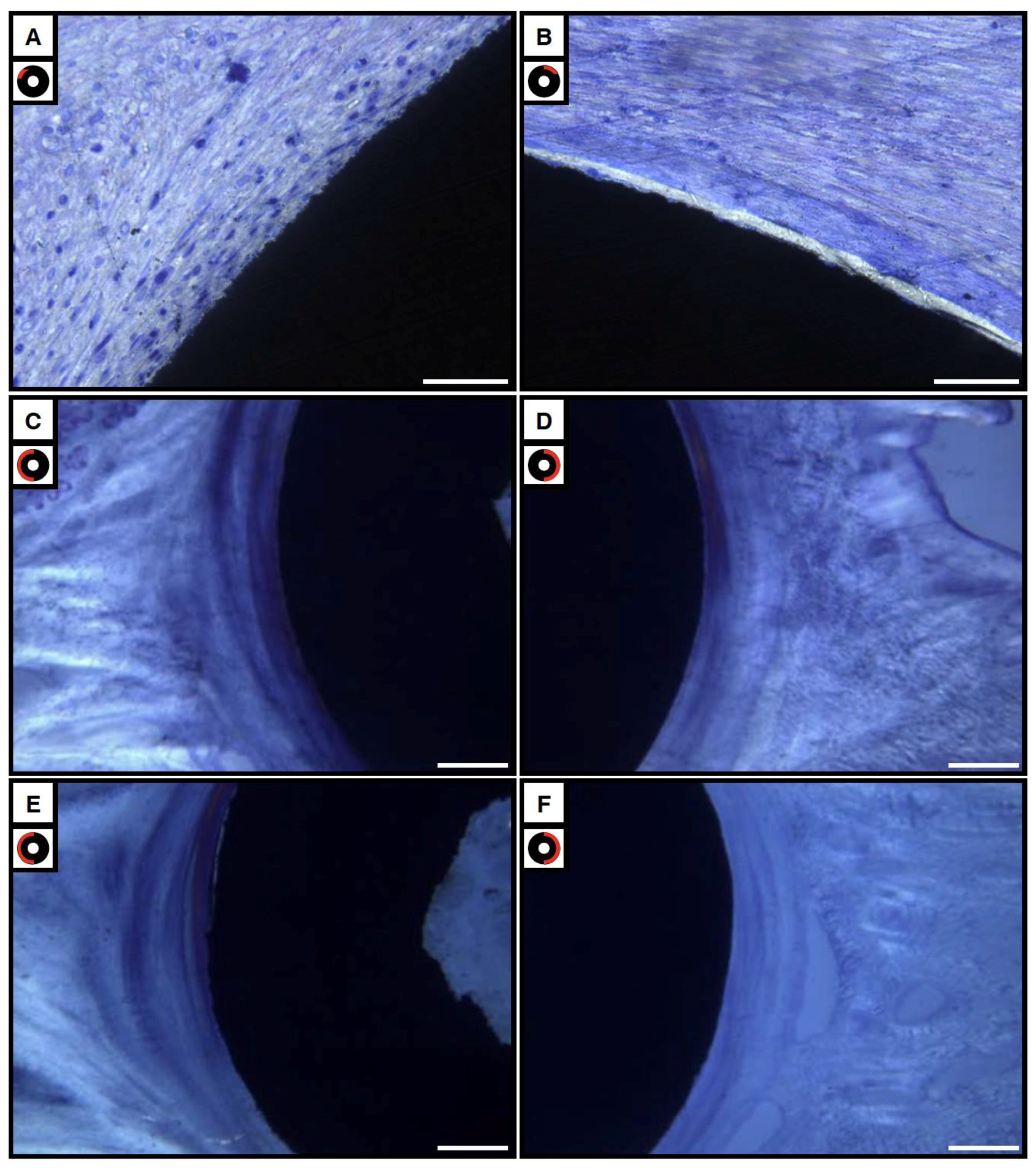
3.4. Soft Tissue Compartment

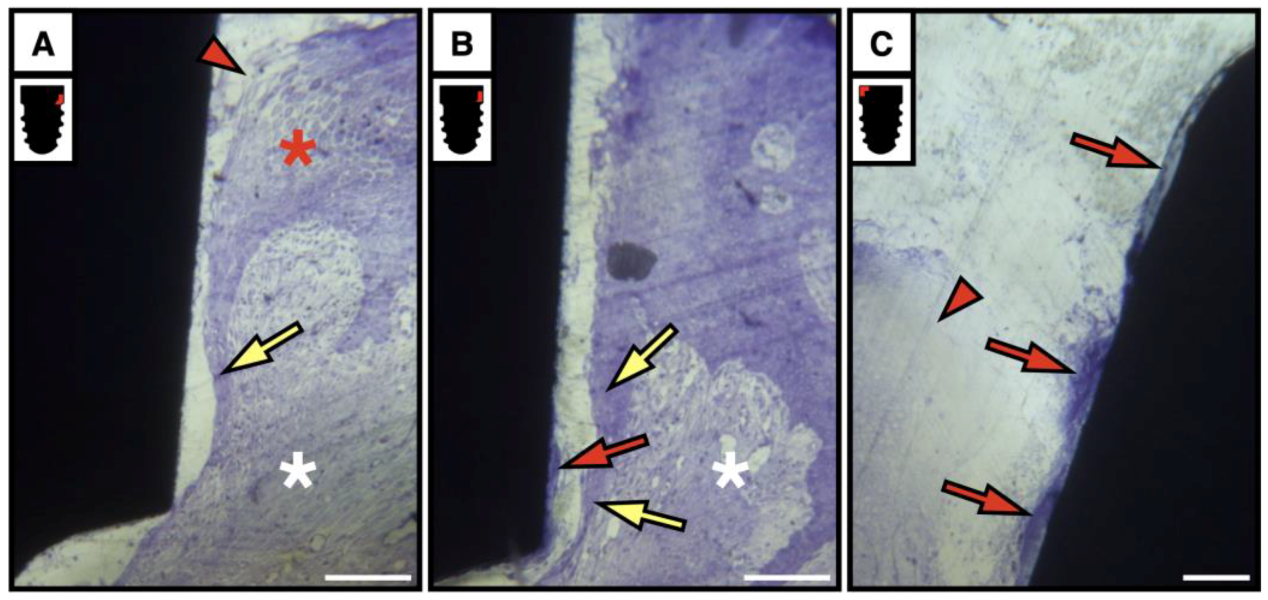
3.4.1. Bright and Polarized Light Microscopy

At early time points, MNGCs were seen in contact with the implant surface predominantly in the soft tissue compartment above the first thread (Figure 8C insert), while in cross-sections, the implant interface was seen to be occupied by cells (Figure 9A). Some cells with elongated nuclei could be identified as fibroblasts, but others with a more oval shape and an eccentrically placed nucleus were putative macrophages. Polarized micrography also showed that, irrespective of the implant type, the predominant orientation of the birefringent fibrous tissue was parallel, and circumferential, to the implant surface (Figure 9B–F). This arrangement was not discernible at 1 week, but it appeared to be well-formed by 3 weeks, with no obvious differences in organization or thickness compared to those seen in the 6-week samples. There were also no notable differences in the birefringent collagen fiber orientation and the fibrous tissue thickness between the four implant types within the same implantation period. At 3 weeks, all implants demonstrated gaps between the implant and the adjacent soft tissue. The presence of gaps, however, diminished in number with time, with almost all the 6-week samples demonstrating an intimate contact at the interface. However, no quantitative assessments could be made due to the low sample size.

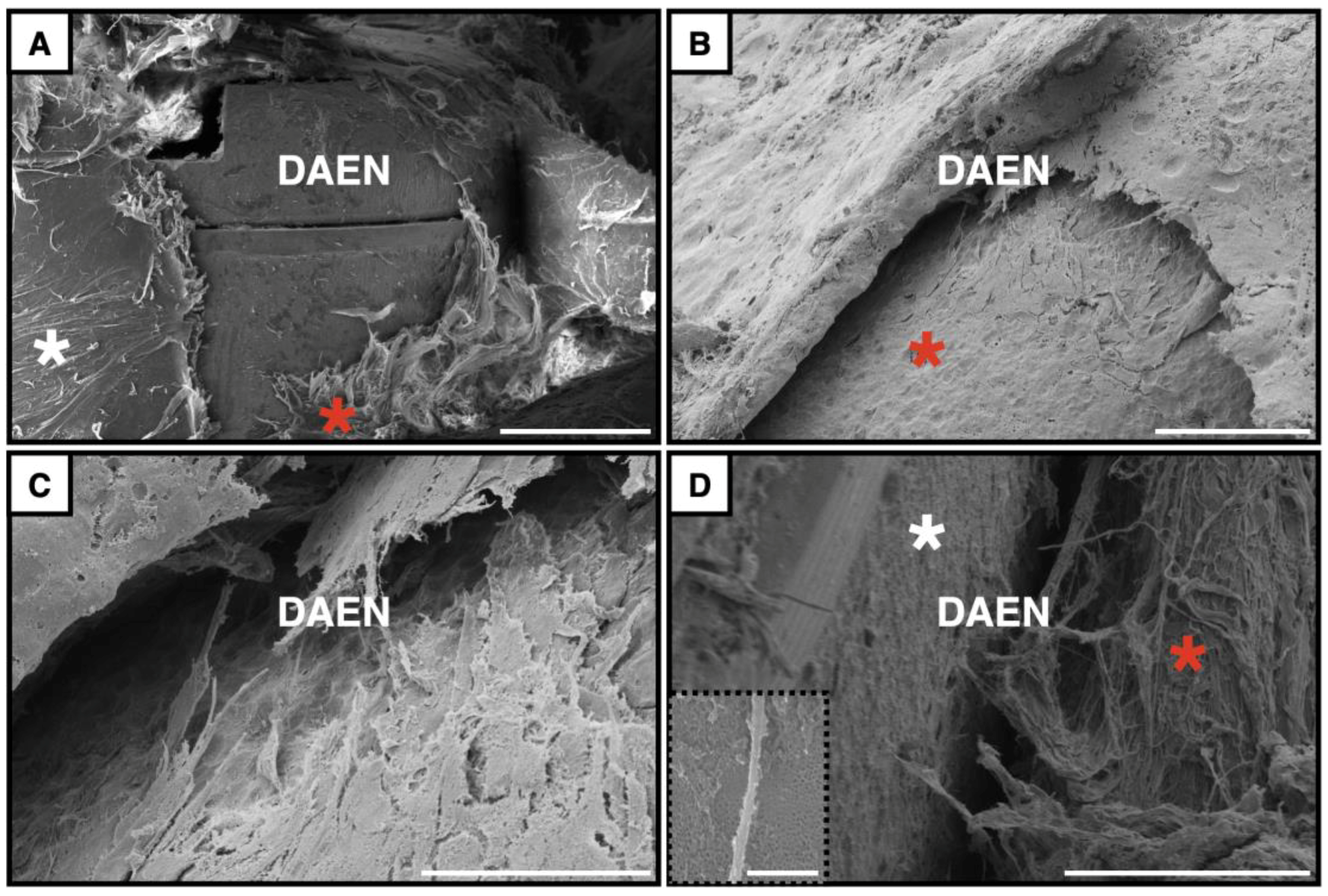
3.4.2. Scanning Electron Microscopy Observations

The overlying soft tissue was reflected before fixation to permit scanning electron micrography of the peri-implant soft tissue layers and the soft tissue/implant interface. As seen by polarized micrography, the predominant orientation of the peri-implant soft tissue was parallel and circumferential to the implant surface, although some deeper fibers were arranged parallel and longitudinally (Figure 10A). Within this soft tissue, sheets of cells could be found (Figure 10B). The close packing of these tessellated polygonal cells formed a continuous sheet without discernable cell boundaries and was most evident at locations where the tissue had ripped during the reflection procedure. Furthermore, they were separated from the implant surface by a fine fibrous matrix (Figure 10B,C). In some areas, occasional fibers were oriented perpendicular to the implant surface, although, at higher magnification, these were entangled in deeper unorganized fine-structured fibers juxtaposed, and running parallel, to the implant surface (Figure 10D). Occasionally, extended cell processes approximately 140–200 nm wide were observed traversing the implant surface and possessed lateral extensions that were small enough to enter into the openings of the nanotubes (Figure 10D insert).
Closer to the implant surface, there was relatively little cellular attachment and matrix deposition on the M surface at one week compared to the other three surfaces. This difference was also evident at 3 weeks but more pronounced at 6 weeks (Figure 11). The latter shows cell processes and matrix deposition within the craters of the DAE surface, which, in some areas, almost obliterated the underlying surface. However, in the case of the nanotube surfaces, MN and DAEN, while the nanotubes could still be identified, there was a mass of closely adherent fine fibers and tissue, especially at structural changes on the implant surface, such as the junction between the implant and cover screw.

3.5. A Note on the Prematurely Exposed Samples

Clinically, the peri-implant soft tissues around the prematurely exposed implants appeared to form a healthy collar with a sulcus around the exposed coronal implant/cover screw. However, when the samples were examined by bright-field microscopy, it was found that the structures normally expected to be present around healing abutments were absent. The epithelium lining of the implant/soft tissue interface was highly irregular and disrupted due to the breach of exposure and torn away from the fixture (Figure 12). Nevertheless, an epithelial architecture similar to a junctional epithelium had developed, even in the single 1-week sample that was exposed, although not in contact with the implant surface. At both 3 and 6 weeks, islands of tissue were still adherent to the lateral surface of the implant down to the first thread, presumably established before the breach. Importantly, the underlying connective tissue showed no signs of an inflammatory response, reflecting the clinical observation.

4. Discussion

To our knowledge, our pilot study was the first to report the potential of the rabbit mandibular diastema as an intra-oral experimental implantation site to study the osseointegration of dental implants [2]. The model described herein, which is an extension of the latter, facilitates the investigation of both hard and soft tissue implant interfaces and provides potentially clinically relevant insight into all three tissue interfaces with dental implants (bone, connective tissue, and epithelium). Furthermore, the eight implants exposed to the oral cavity provide evidence that with intentional transmucosal placement, this model could be employed in the future for studies of peri-implant mucositis and peri-implantitis with the adoption of common methods, such as ligature-induced inflammation [28,29].
Regarding the bone/implant interface, much has been written about osseointegration in preclinical and clinical reports. We did not attempt, herein, to assess the degree of osseointegration, as we have done elsewhere [20]. However, qualitatively, all the implants were stable at each time point.
The intramembranous ossification that occurred independent of any solid surface (Figure 8B), although recently proposed [30], has, to our knowledge, never been histologically demonstrated in a peri-implant healing compartment nor described as a mechanism of endosseous integration. This was clearly a form of de novo bone formation, although we have previously only used this term in the context of contact osteogenesis where the formed interface is occupied by a cement line matrix. While the cement line would not be expected in such a “soft tissue” environment, previous transmission electron microscopy (TEM) has shown that mineralized islands do occur in advance of such growing bone spicules [31]. With the resin embedding we employed, it would be possible to create ultra-thin sections in selected areas, devoid of the metallic implant, to study such a phenomenon.
Immunohistochemical staining of thin TEM sections has been employed for decades [32,33], and the adoption of such techniques to the peri-implant compartment will facilitate the staining and labeling of various cell phenotypes that have, hitherto, been refractory to identification.
An osseointegrated bone/implant interface is an ankylosis rather than a gomphosis, as seen in natural dentition. Similarly, the structure of the connective tissue attachment to the implant surface does not recapitulate the natural dental interface where Sharpey’s fibers [34] are embedded within the mineralized cementum. Importantly, it should be emphasized that collagen fibers appear during the development of the periodontal membrane, and then become surrounded by, and embedded in, the mineralizing cementum. The resulting robust anchorage of dentogingival fibers blocks the downgrowth of the junctional epithelium [35].
Although our results show an intimate relationship of fine collagen fibers with the topographically complex implant surfaces (Figure 10 and Figure 11), this begs the question: Are such arrangements of functional significance? We do not believe so. Indeed, for each implant surface employed, the major connective tissue architecture was characterized by a thick layer of circumferential fibers. This is in agreement with the reports of others [36,37,38]. Indeed, Schupbach and Glauser [36] described fibers running both circumferentially and longitudinally parallel to the implant surface (also see Figure 10A), with a third less prominent group from the latter obliquely to the implant surface. Further evaluation of their course showed that they never reached the abutment surface but were separated from it by a 25 nm thick layer of proteoglycans (P. Schupbach, personal communication), in agreement with other reports [39].
However, with certain implant surfaces exhibiting complex three-dimensional topographies, a pseudo-gomphotic arrangement may be achieved. Deporter and colleagues (1988) showed collagen fibers oriented, in an apparently functional arrangement, perpendicular or oblique to a titanium alloy bead-coated implant surface [40], where the collagen fibers wrapped around the stepped bead surface structure of the implant [41]. Similarly, Nevins et al. (2008) demonstrated, in human patients, that an apparent functional collagen fiber orientation could be achieved with a laser-ablated titanium implant surface [42]. They concluded that their polarized light and scanning electron microscopic evaluations demonstrated a “physical connective tissue attachment” to the implant surface. While inevitably the same mechanism as that in the bead-coated titanium alloy example, the scale range of the laser-ablated surface is an order of magnitude smaller than the former. More recently Liñares et al. also showed the oblique orientation of collagen fibers to the transmucosal component of an acid-etched titanium/zirconium alloy implant with surface features another order of magnitude smaller than those of the laser-ablated surface [43]; however, they cautioned that their studies were limited by small sample sizes. Therefore, the question remains: What is the scale range of implant topography that can reproducibly result in a functional pseudo-gomphotic soft tissue relationship? To address this question, using our model, it would be necessary to employ the longer time points shown to be feasible in the pilot study [2]. This could extend recent in vitro findings employing primary and immortalized cells cultured on titanium disks [44]. Furthermore, it would be necessary to refine our surface roughness measurements by the addition of atomic force microscopy to quantify the topographic differences seen in the SEM images but not registered by the optical microscope employed herein.
The soft tissue/implant interfaces represent important challenges in the surface design of dental implants. Unlike the connective tissue/implant interface, that of the epithelium may more closely reflect the natural example. Our experimental design placed implants below the oral epithelium and, thus, we cannot directly address this issue (see Figure 12). Nevertheless, those implants that perforated the oral epithelium during the implantation period suggest that the model could provide a means of recapitulating this interface in future studies.
The peri-implant mucosa comprises a well-keratinized oral epithelium, a para-keratinized sulcular epithelium, and a non-keratinized junctional epithelium (JE) [45]. The JE is attached to enamel by the so-called epithelial attachment apparatus, which comprises hemidesmosomes attached to the internal basal lamina (IBL) [46]. Importantly, the epithelial attachment apparatus is formed during the process of tooth eruption [47], and the enamel cuticle is retained as an integral part of the IBL, which is synthesized by the epithelial cells directly attached to the tooth (DAT cells) and considered unique to basement membranes [48]. The suprabasal stratum of the JE faces the implant surface—the cells of which are derived from the reparative epithelium rather than the reduced enamel epithelium in the natural JE. Although human and animal studies have demonstrated that the structure and function of the implant JE may correspond to that around natural teeth [36,46,49,50,51,52,53,54], the data are insufficient to permit a definitive conclusion since no study has shown an internal basal lamina in direct contact with a metallic implant surface.
Thus, the precise structure of the epithelial and soft connective tissue/implant interfaces has not yet been accurately analyzed, in part due to the difficulties in using transmission electron microscopy (TEM) without removing the metallic, or ceramic, implant. This challenge could be overcome by using focused ion beam (FIB) techniques, although we are unaware of such studies to date on such soft tissue interfaces. As the name implies, FIB uses a powerful and focused beam of ions to “cut” and lift out a small sample from a resin-embedded sample, whose surface can be simultaneously visualized using a scanning electron beam [55], and provide near atomic-resolution specimen analysis [56].
However, perhaps a greater challenge to implant surface design is that, ideally, the implant/soft tissue interface should provide a bacterial seal through tissue adhesion to the implant surface. But, importantly, it should not simultaneously provide a surface that increases bacterial adhesion. Thus, some attempts to increase soft tissue attachment by increasing implant surface topography may come at a potential cost since recent evidence has shown that surfaces of greater than approximately 1-micron topography facilitate greater bacterial adhesion [57].
The method described herein provides the distinct advantage of investigating the formed interfaces of a putative dental implant with bone, connective tissue, and epithelium in a lagomorph, rather than a higher vertebrate, with the attendant reduction in costs and regulatory challenges. However, one disadvantage is that the surgery is more demanding than simply inserting an implant into the appendicular skeleton since custom-made mini-implants and insertion tools are required, together with some form of magnification for the surgeon. Adding a surgical microscope to the armamentarium would render the approach feasible in rodents (as we have already shown in rats [2]) with the libraries of antibodies and other marker molecules available for mice that have not been developed for lagomorphs.
In addition, given the exploratory nature of this study, the retrieved implants were used for different implantation periods, fixation, embedding, staining, and light and scanning electron microscopy techniques, rendering the numbers per specific group too small for statistical analysis—although, we do include numerical comparisons in the measurement of staining density in a forthcoming report [21]. Nevertheless, the broad number of analytical methods employed illustrate the range of potential studies that could be conducted in the future with this surgical approach, among which, as mentioned above, is the possibility of studying the mechanisms of peri-mucositis and peri-implantitis and clearly distinguishing them from non-infected soft and hard tissue healing, as we report herein.

5. Conclusions

The rabbit mandibular diastema provides an intra-oral method of implant placement without the necessity of an extra-oral approach, tooth extractions, or bone augmentation procedures. Furthermore, given that three implant tissue interfaces can potentially be studied (bone, connective tissue, and epithelium), this model provides advantages over more traditional implant placement sites in the appendicular skeleton.

Author Contributions

Conceptualization, J.E.D.; methodology, C.T., R.N. and N.W.; formal analysis, R.N., N.W., C.T. and J.E.D.; resources, J.E.D.; writing—original draft preparations, R.N., N.W. and C.T.; writing—review and editing, J.E.D.; supervision, J.E.D.; funding acquisition, J.E.D. All authors have read and agreed to the published version of the manuscript.

Funding

We thank Zimmer Biomet Dental, Palm Beach Gardens, FL, who partially funded this study and also supplied the custom-made implants and cover screws. Particular thanks are given to Elnaz Ajami for coordinating our collaboration. Zimmer Biomet Dental had no input in the study design, analysis, or discussion of the results.

Institutional Review Board Statement

This study was conducted in accordance with the Health Sciences Local Animal Care Committee of the Faculty of Medicine, University of Toronto (Protocol #20012429, approval date: 14 September 2019).

Informed Consent Statement

Not applicable.

Data Availability Statement

The original contributions presented in this study are included in the article. Further inquiries can be directed to the corresponding author.

Acknowledgments

We gratefully acknowledge the surgical and laboratory assistance of Zhen-Mei Liu and Sophie Yang, the expert help of Rainerio de Guzman of the Department of Comparative Medicine of the University of Toronto, and the technical support of Nancy Valiquette and Aiman Ali of the University of Toronto Faculty of Dentistry Histology facilities.

Conflicts of Interest

John E. Davies has received research funding from ZimVie, including partial support for the current study. ZimVie had no involvement in the design of the study; in the collection, analyses, or interpretation of data; in the writing of the manuscript, or in the decision to publish the results. The other authors declare no conflict of interest.

Abbreviations

The following abbreviations are used in this manuscript:
MNGCsmultinucleate giant cells
Mmachined surface
MNmachined surface with nanotubes
DAEdual-acid-etched surface
DAENdual-acid-etched surface with nanotubes
microCTmicro-computed tomography
SEMscanning electron microscopy
TEMtransmission electron microscopy
PMMApoly-methyl methacrylate
TRAPtartrate-resistant acid phosphatase
JEjunctional epithelium
IBLinternal basal lamina
DAT cellsdirectly attached to tooth cells
FIBfocused ion beam

References

  1. Karoussis, I.K.; Salvi, G.E.; Bürgin, W.; Lang, N.P. Effect of implant design on survival and success rates of titanium oral implants: A 10-year prospective cohort study of the ITI Dental Implant System. Clin. Oral Implants Res. 2004, 15, 8–17. [Google Scholar] [CrossRef] [PubMed]
  2. Tremblay, C. Development of a New Experimental Model for Investigating Osseointegration of Titanium Mini-Screws Placed Intraorally. Master’s Thesis, University of Toronto, Toronto, ON, Canada, 2020. Available online: http://hdl.handle.net/1807/101040 (accessed on 13 April 2025).
  3. Yazan, M.; Atil, F.; Gonen, Z.B.; Kocyigit, I.D.; Tekin, U. A Novel Experimental Model for Dental Implant Research. Int. J. Exp. Dent. Sci. 2018, 7, 43–47. [Google Scholar] [CrossRef]
  4. Freilich, M.; Shafer, D.; Wei, M.; Kompalli, R.; Adams, D.; Kuhn, L. Implant system for guiding a new layer of bone. Computed microtomography and histomorphometric analysis in the rabbit mandible. Clin. Oral Implants Res. 2009, 20, 201–207. [Google Scholar] [CrossRef]
  5. Cordioli, G.; Atiyeh, F.; Piattelli, A.; Majzoub, Z. Healing of transplanted composite bone grafts–implants: A pilot animal study. Clin. Oral Implants Res. 2003, 14, 750–758. [Google Scholar] [CrossRef]
  6. Munhoz, E.A.; Bodanezi, A.; Cestari, T.M.; Taga, R.; de Carvalho, P.S.; Ferreira, O., Jr. Long-term rabbits bone response to titanium implants in the presence of inorganic bovine-derived graft. J. Biomater. Appl. 2012, 27, 91–98. [Google Scholar] [CrossRef]
  7. Munhoz, E.A.; Bodanezi, A.; Cestari, T.M.; Taga, R.; Ferreira, O., Jr.; de Carvalho, P.S. Biomechanical and Microscopic Response of Bone to Titanium Implants in the Presence of Inorganic Grafts. J. Oral Implantol. 2011, 37, 19–25. [Google Scholar] [CrossRef]
  8. Munhoz, E.A.; Bodanezi, A.; Biol, T.M.C.; Graeff, M.S.Z.; Ferreira, O., Jr.; de Carvalho, P.S.; Taga, R. Impact of Inorganic Xenograft on Bone Healing and Osseointegration: An Experimental Study in Rabbits. Implant Dent. 2017, 26, 875–881. [Google Scholar] [CrossRef]
  9. Weber, J.B.B.; Mayer, L.; Cenci, R.A.; Baraldi, C.E.; Ponzoni, D.; Gerhardt de Oliveira, M. Effect of Three Different Protocols of Low-Level Laser Therapy on Thyroid Hormone Production After Dental Implant Placement in an Experimental Rabbit Model. Photomed. Laser Surg. 2014, 32, 612–617. [Google Scholar] [CrossRef]
  10. Yu, Y.; Zhu, W.Q.; Xu, L.N.; Ming, P.P.; Shao, S.Y.; Qiu, J. Osseointegration of titanium dental implant under fluoride exposure in rabbits: Micro-CT and histomorphometry study. Clin. Oral Implants Res. 2019, 30, 1038–1048. [Google Scholar] [CrossRef]
  11. AlOtaibi, N.M.; Dunne, M.; Ayoub, A.F.; Naudi, K.B. A novel surgical model for the preclinical assessment of the osseointegration of dental implants: A surgical protocol and pilot study results. J. Transl. Med. 2021, 19, 276. [Google Scholar] [CrossRef]
  12. Donnelly, T.M.; Vella, D. Anatomy, Physiology and Non-dental Disorders of the Mouth of Pet Rabbits. Veterinary Clin. N. Am. Exot. Anim. Pract. 2016, 19, 737–756. [Google Scholar] [CrossRef]
  13. Choe, S.; Ma, T.; Jones, D.; Shiau, H.J.; Saito, H. Peri-implant mucosal tissue attachment: Narrative review. Dent. Rev. 2024, 4, 100141. [Google Scholar] [CrossRef]
  14. Renvert, S.; Polyzois, I. Risk indicators for peri-implant mucositis: A systematic literature review. J. Clin. Periodontol. 2015, 42, 172–186. [Google Scholar] [CrossRef] [PubMed]
  15. Kroger, A.; Hülsmann, C.; Fickl, S.; Spinell, T.; Hüttig, F.; Kaufmann, F.; Heimbach, A.; Hoffmann, P.; Enkling, N.; Renvert, S.; et al. The severity of human peri-implantitis lesions correlates with the level of submucosal microbial dysbiosis. J. Clin. Periodontol. 2018, 45, 1498–1509. [Google Scholar] [CrossRef]
  16. Berglundh, T.; Armitage, G.; Araujo, M.G.; Avila-Ortiz, G.; Blanco, J.; Camargo, P.M.; Chen, S.; Cochran, D.; Derks, J.; Figuero, E.; et al. Consensus report of workgroup 4 of the 2017 World Workshop on the Classification of Periodontal and Peri-Implant Diseases and Conditions. J. Clin. Periodontol. 2018, 45 (Suppl. S20), S286–S291. [Google Scholar] [CrossRef]
  17. Jepsen, S.; Berglundh, T.; Genco, R.; Aass, A.M.; Demirel, K.; Derks, J.; Figuero, E.; Giovannoli, J.L.; Goldstein, M.; Lambert, F.; et al. Primary prevention of peri-implantitis: Managing peri-implant mucositis. J. Clin. Periodontol. 2015, 42, 152–157. [Google Scholar] [CrossRef]
  18. Masoud, I.; Shapiro, F.; Moses, A. Longitudinal roentgencephalometric study of the growth of the New Zealand white rabbit: Cumulative and biweekly incremental growth rates for skull and mandible. J. Craniofacial Genet. Dev. Biol. 1986, 6, 259–287. [Google Scholar] [CrossRef]
  19. Stübinger, S.; Dard, M. The Rabbit as Experimental Model for Research in Implant Dentistry and Related Tissue Regeneration. J. Investig. Surg. 2013, 26, 266–282. [Google Scholar] [CrossRef]
  20. Liddell, R.S.; Ajami, E.; Li, Y.; Bajenova, E.; Yang, Y.; Davies, J.E. The influence of implant design on the kinetics of osseointegration and bone anchorage homeostasis. Acta Biomater. 2021, 121, 514–526. [Google Scholar] [CrossRef]
  21. Warda, N.; Noh, R.; Davies, J.E. TRAP-Positive Cells: Potential Mediators of Peri-Implant Bone Healing. Master’s Thesis, University of Toronto, Toronto, ON, Canada. manuscript in preparation.
  22. Noh, R. Investigation of Soft Tissue Healing around Osseointegrated Titanium Mini-Implants Placed in the Mandibular Diastema of Rabbits. Master’s Thesis, University of Toronto, Toronto, ON, Canada, 2022. Available online: http://hdl.handle.net/1807/125654 (accessed on 13 April 2025).
  23. Velasco-Ortega, E.; Ortiz-Garcia, I.; Jiménez-Guerra, A.; Núñez-Márquez, E.; Moreno-Muñoz, J.; Rondón-Romero, J.L.; Cabanillas-Balsera, D.; Gil, J.; Muñoz-Guzón, F.; Monsalve-Guil, L. Osseointegration of Sandblasted and Acid-Etched Implant Surfaces. A Histological and Histomorphometric Study in the Rabbit. Int. J. Mol. Sci. 2021, 22, 8507. [Google Scholar] [CrossRef]
  24. de Barros e Lima Bueno, R.; Ponce, K.J.; Dias, A.P.; Guadarrama Bello, D.; Brunski, J.B.; Nanci, A. Influence of 528 nanotopography on early bone healing during controlled implant loading. Nanomaterials 2020, 10, 2191. [Google Scholar] [CrossRef] [PubMed]
  25. Kligman, S.; Ren, Z.; Chung, C.H.; Perillo, M.A.; Chang, Y.C.; Koo, H.; Zheng, Z.; Li, C. The Impact of Dental Implant Surface Modifications on Osseointegration and Biofilm Formation. J. Clin. Med. 2021, 10, 1641. [Google Scholar] [CrossRef] [PubMed]
  26. Mattheck, C. Design in Nature—Learning from Trees; Springer: Berlin/Heidelberg, Germany, 1998. [Google Scholar]
  27. Warda, N. TRAP+ Cells: Potential Mediators of Peri-Implant Bone Healing. Master’s Thesis, University of Toronto, Toronto, ON, Canada, 2022. Available online: http://hdl.handle.net/1807/125683 (accessed on 13 April 2025).
  28. Reinedahl, D.; Chrcanovic, B.; Albrektsson, T.; Tengvall, P.; Wennerberg, A. Ligature-Induced Experimental Peri-Implantitis-A Systematic Review. J. Clin. Med. 2018, 7, 492. [Google Scholar] [CrossRef]
  29. de Araújo Silva, D.N.; Casarin, M.; Monajemzadeh, S.; Menezes da Silveira, T.; Lubben, J.; Bezerra, B.; Pirih, F.Q. Experimental Model of Ligature-Induced Peri-Implantitis in Mice. J. Vis. Exp. 2024, 207, e66316. [Google Scholar] [CrossRef]
  30. Shah, F.A.; Ruscsák, K.; Palmquist, A. 50 years of scanning electron microscopy of bone—A comprehensive overview of the important discoveries made and insights gained into bone material properties in health, disease, and taphonomy. Bone Res. 2019, 7, 15. [Google Scholar] [CrossRef]
  31. Davies, J.; Hosseini, M. Histodynamics of Endosseous Wound Healing. In Bone Engineering; Davies, J.E., Ed.; EM Squared: Toronto, ON, Canada, 2000; pp. 1–14. [Google Scholar]
  32. Polak, J.M.; Priestley, J.V. Electron Microscopic Immunocytochemistry, Principles and Practices; Oxford University Press: Oxford, UK, 1992. [Google Scholar]
  33. Graham, L.; Orenstein, J. Processing tissue and cells for transmission electron microscopy in diagnostic pathology and research. Nat. Protoc. 2007, 2, 2439–2450. [Google Scholar] [CrossRef]
  34. Kuroiwa, M.; Chihara, K.; Higashi, S. Electron microscopic studies on Sharpey’s fibers in the alveolar bone of rat molars. Kaibogaku Zasshi 1994, 69, 776–782. [Google Scholar] [PubMed]
  35. Schroeder, H.E.; Listgarten, M.A. The junctional epithelium: From strength to defense. J. Dent. Res. 2003, 82, 158–161. [Google Scholar] [CrossRef]
  36. Schupbach, P.; Glauser, R. The defense architecture of the human periimplant mucosa: A histological study. J Prosthet. Dent. 2007, 97 (Suppl. S6), S15–S25. [Google Scholar] [CrossRef]
  37. Vignoletti, F.; de Sanctis, M.; Berglundh, T.; Abrahamsson, I.; Sanz, M. Early healing of implants placed into fresh extraction sockets: An experimental study in the beagle dog. III: Soft tissue findings. J. Clin. Periodontol. 2009, 36, 1059–1066. [Google Scholar] [CrossRef]
  38. Glauser, R.; Schupbach, P. Early bone formation around immediately placed two-piece tissue-level zirconia implants with a modified surface: An experimental study in the miniature pig mandible. Int. J. Implant Dent. 2022, 8, 37. [Google Scholar] [CrossRef] [PubMed]
  39. Al Rezk, F.; Trimpou, G.; Lauer, H.C.; Weigl, P.; Krockow, N. Response of soft tissue to different abutment materials with different surface topographies: A review of the literature. Gen. Dent. 2018, 66, 18–25. [Google Scholar] [PubMed]
  40. Deporter, D.A.; Watson, P.A.; Pilliar, R.M.; Howley, T.P.; Winslow, J. A histological evaluation of a functional endosseous, porous-surfaced, titanium alloy dental implant system in the dog. J. Dent. Res. 1988, 67, 1190–1195. [Google Scholar] [CrossRef] [PubMed]
  41. Pilliar, R.M.; Davies, J.E.; Smith, D.C. The bone-biomaterial interface for load-bearing implants. MRS Bull. 1991, 9, 55–61. [Google Scholar] [CrossRef]
  42. Nevins, M.; Nevins, M.L.; Carnelo, M.; Boyesen, J.L.; Kim, D.M. Human histologic evidence of a connective tissue attachment to a dental implant. Int. J. Periodontics Restor. Dent. 2008, 28, 111–121. [Google Scholar] [PubMed]
  43. Liñares, A.; Domken, O.; Dard, M.; Blanco, J. Peri-implant soft tissues around implants with a modified neck surface. Part 1. Clinical and histometric outcomes: A pilot study in minipigs. J. Clin. Periodontol. 2013, 40, 412–420. [Google Scholar] [CrossRef]
  44. Bellon, B.; Pippenger, B.; Stähli, A.; Degen, M.; Parisi, L. Cementum and enamel surface mimicry influences soft tissue cell behavior. J. Periodontal Res. 2025, 60, 64–76. [Google Scholar] [CrossRef]
  45. Schroeder, H.E.; Listgarten, M. The gingival tissues: The architecture of periodontal protection. Periodontology 2000 1997, 13, 91–120. [Google Scholar] [CrossRef]
  46. Bosshardt, D.D.; Lang, N.P. The junctional epithelium: From health top disease. J. Dent. Res. 2005, 84, 9–20. [Google Scholar] [CrossRef]
  47. Ten Cate, A.R. Oral Histology Development, Structure, and Function; C.V. Mosby: St. Louis, MO, USA, 1980; pp. 234–238. [Google Scholar]
  48. Hormia, M.C.; Sahlberg, C.I.; Thesleff, I.; Airenne, T. The epithelium-tooth interface−−A basal lamina rich in Laminin-5 and lacking other known laminin isoforms. J. Dent. Res. 1998, 77, 1479–1485. [Google Scholar] [CrossRef]
  49. James, R.A.; Schulz, R.L. Hemidesmosomes and the adhesion of junctional epithelial cells to metal implants—A preliminary report. Oral. Implantol. 1974, 4, 294–302. [Google Scholar] [PubMed]
  50. Listgarten, M.A.; Lai, C.H. Ultrastructure of the intact interface between an endosseous epoxy resin dental implant and the host tissues. J. Biol. Buccale 1975, 3, 13–28. [Google Scholar] [PubMed]
  51. Hansson, H.A.; Albrektsson, T.; Brånemark, P.-I. Structural aspects of the interface between tissue and titanium implants. J. Prosthet. Dent. 1983, 50, 108–113. [Google Scholar] [CrossRef] [PubMed]
  52. Gould, T.R.; Westbury, L.; Brunette, D.M. Ultrastructural study of the attachment of human gingiva to titanium in vivo. J. Prosteth Dent. 1984, 52, 418–420. [Google Scholar] [CrossRef]
  53. Listgarten, M.A. Soft and hard tissue response to endosseous dental implants. Anat. Rec. 1996, 245, 410–425. [Google Scholar] [CrossRef]
  54. Lilienberg, B.; Gualin, F.; Berglundh, T.; Tonetti, M.; Lindhe, J. Some characteristics of the ridge mucosa before and after implant installation. A prospective study in humans. J. Clin. Periodontol. 1996, 23, 1008–1013. [Google Scholar] [CrossRef]
  55. Jarmar, T.; Palmquist, A.; Brånemark, R.; Hermansson, L.; Engqvist, H.; Thomsen, P. Technique for preparation and characterization in cross-section of oral titanium implant surfaces using focused ion beam and transmission electron microscopy. J. Biomed. Mater. Res. Part A 2008, 87, 1003–1009. [Google Scholar] [CrossRef]
  56. Grandfield, K.; Engqvist, H. Focused Ion Beam in the Study of Biomaterials and Biological Matter. Adv. Mater. Sci. Eng. 2012, 2012, 841961. [Google Scholar] [CrossRef]
  57. Wang, X.; Liddell, R.S.; Wen, H.B.; Davies, J.E.; Ajami, E. The role of implant coronal surface properties on early adhesion of streptococcus oralis—An in vitro comparative study. J. Biomed. Mater. Res. A 2025, 113, e37866. [Google Scholar] [CrossRef]
Figure 1. (A) The custom-designed mini-implants made of titanium alloy with a cover screw. (B) The custom-designed quad-shaping drill (a) with stop (b) to ensure the correct depth of cut.
Surgeries 06 00036 g001
Figure 2. The main photo shows a rabbit on a surgical table fitted with a mouth gag (horizontal bars) and a modified superglottic airway in place. The latter is seen more clearly in (A), where the lateral flange has been removed to facilitate oral access. (B,C) Dissection of the soft tissue to expose the underlying mandibular diastema, (D) insertion of an implant using a custom implant driver, (E) 2 implants placed, and (F) flap closure: the sutures are just visible in the buccal sulcus, while the cover screws of both implants are clearly visible through the translucent gingival tissue.
Surgeries 06 00036 g002
Figure 3. (AD) show the stages of incision, mandibular exposure, implant placement, and flap closure. (EI) show the marking of the positions for the osteotomies, initial drilling, use of the quad-shaping drill, and implant insertion with the aid of the custom implant driver.
Surgeries 06 00036 g003
Figure 4. Low-magnification scanning electron photomicrographs of the (A) machined (M), (B) machined nanotube (MT), (C) dual-acid-etched (DAE), and (D) the latter with nanotubes (DEAN) implant surfaces. Scale bars = 30 microns.
Surgeries 06 00036 g004
Figure 5. Higher-magnification scanning electron photomicrograph showing a fractured and reflected nanotube surface on a DAEN sample. Note: The thickness of the nanotube coating is 220–290 microns, as measured in the red brackets. Scale bar = 1 micron.
Surgeries 06 00036 g005
Figure 6. (A) A harvested complete mandible. Two implants are clearly seen in the right mandibular diastema while both implants in the left diastema have perforated the mucogingiva and become exposed to the oral cavity. The latter are still visible through the entangled mass of hair and debris that filled the peri-implant sulcus. Note the lack of inflammatory peri-implant soft tissue. The insert shows a single exposed implant from a different specimen. Again, note the lack of inflammatory tissue and evidence of some increased circumferential connective tissue, which is pronounced on the distal side. (BD) Decalcified histology images from a cadaveric sample (see text) showing (B) the para-keratinized oral epithelium and underlying fat and salivary gland tissue and (C,D) the attachment of the buccinator to the lingual ridge of the mandibular diastema. The muscle was detached and moved laterally with the fat and salivary tissue during the surgical procedure, and the lingual mandibular ridge was reduced to accommodate the implant head on the superior surface of the diastema. Field widths for (BD): 2.45, 2.85, and 1.37 mm, respectively.
Surgeries 06 00036 g006
Figure 7. X-rays of hemi-mandibles (A) at 3 weeks showing significant saucerization of the alveolar bone and (B) at 6 weeks, where developing radio-opacity has replaced the saucerization. (CE) MicroCT images of anterior (M) and posterior (MN) implants. (D) is a 3-D lingual view image, while (C,E) are diagnostic images illustrating bone deposition at the mesial and distal alveolar crest. The red lines mark the original alveolar crest level, and the vertical arrows show the extent of new bone growth above the latter.
Surgeries 06 00036 g007
Figure 8. The endosseous compartment. (i) = implant. (A) Polarized microscopy showing original (red asterisks) and new bone (darker blue with white asterisks) and evidence of both contact (yellow arrows) and distance (red arrow) osteogenesis. (B,C) Light-green-and-toluidine-blue-stained Osteobed sections showing (B) an area of intramembranous bone formation (red arrows) and (C) the original bone of the alveolar crest together with the connective tissue compartment above. The inset shows a multinucleated cell attached to the implant surface. (DF) Technovit-embedded sections stained with tartrate-resistant acid phosphatase (TRAP) and counterstained with toluidine blue. (D) TRAP+ osteoclasts lying in Howship’s lacunae on the bone surface (yellow arrows) and other multinucleate cells in the peri-implant compartment but not in contact with the bone surface. (E,F) both show weakly stained TRAP+ cells on the implant surface and, in one case (yellow arrow in (E)), a TRAP+ cell that may be in contact with both bone and implant surfaces. Scale bars = 50 microns.
Surgeries 06 00036 g008
Figure 9. The connective tissue compartment. (A) Bright-field: At early time points, the implant interface was occupied by cells. Some with elongated nuclei are identified as fibroblasts, but others with a more oval shape and an eccentrically placed nucleus may be macrophages. (B) Polarized light: This cellular interface developed gaps with the implant surface seen on all implant surfaces at 3 weeks, which had resolved by 6 weeks, as shown in (C,D). DAEN and DAE implants at 3 weeks. (E,F) DAEN and MN implants at 6 weeks. The circumferential arrangement of the birefringent collagen fibers is evident. Scale bars: (A,B) = 50 microns; (CF) = 250 microns.
Surgeries 06 00036 g009
Figure 10. Six-week samples of a DAEN implant: (A) Low-magnification SEM showing an implant in situ after the peri-implant soft tissue was gently reflected before fixation to expose the surfaces of both the implant and cover screw. Note both the circumferentially (white asterisk) and longitudinally (red asterisk) oriented fibers parallel to the implant surface. (B) A sheet of cells running parallel to the implant surface but separated from the latter by a layer of fine collagen fibers. (C) A higher magnification of the image in (B) showing where the tessellated layer of polygonal cells was disrupted during tissue preparation. (D) The DAEN surface (white asterisk) with reflected peri-implant soft tissue (red asterisk) at 6 weeks. Note the fine collagen fibers directed obliquely to the implant surface that did not detach during the preparation prior to fixation (see text). They are not attached to the implant surface but entangled in the finer fibers covering the implant surface (see Figure 10). Scale bars: (A) = 500 microns; (B,D) = 100 microns; (C) = 40 microns. The insert shows a single-cell process with lateral extensions entering the nanopores of the implant surface. Scale Bar = 1 micron.
Surgeries 06 00036 g010
Figure 11. Representative SEM photomicrographs of the tissue adherent to the 4 implant surfaces employed. (A) The M surface exhibits little tissue adhesion. (B) The DAE surface has tissue and cell processes entering into the acid-etched craters. (C,D) show the mass of fine fibrils and cell processes covering the MN and DAEN surfaces, respectively, with the nanotube surface structure clearly visible in many areas. All scale bars = 3 microns.
Surgeries 06 00036 g011
Figure 12. Representative examples of the epithelium surrounding 3 of the 8 implants that perforated the epithelium and became exposed to the oral cavity, shown here to illustrate (1) the sulcular epithelium (red asterisk) and cell proliferation that resulted in a junctional epithelium-type architecture (yellow arrows), although, in no case was the latter attached to the implant surface, and (2) the lack of evidence, in the underlying connective tissue (white asterisks) of an inflammatory cell infiltrate. (A) One-week M implant, (B) three-week M implant, and (C) six-week MN implant. Note the disrupted epithelial tissue (red arrowheads) and evidence of remaining soft tissue attachment to the implant surfaces (red arrows). Scale bars = 250 microns.
Surgeries 06 00036 g012
Table 1. Components of the Technovit 9100 MMA Embedding Kit.
BasisPowderHardener 1Hardener 2Regulator
Component Number12345
Pre-Infiltration200 mL 1 g
Infiltration250 mL20 g1 g
Stock Solution A500 mL80 g3 g
Stock Solution B500 mL 4 mL2 mL
Polymerization Mixture9 parts (v/v)
1 part (v/v)
plusStock Solution A
Stock Solution B
Table 2. Chemical products for TRAP staining.
Chemical ProductProduct NumberVendor
TRAP Basic Incubation Medium
Sodium Acetate AnhydrousS-2889Sigma-Aldrich
L-(+) Tartaric AcidT-6521
Glacial Acetic AcidA-6283
Napthol AS-MX Phosphate Substrate Mix
Napthol AS-MX PhosphateN-4875Sigma-Aldrich
Ethylene Glycol Monoethyl EtherE-2632
TRAP Staining Solution Mix
TRAP Basic Incubation Medium-Sigma-Aldrich
Fast Red Violet LB SaltF-3381
Napthol AS-MX Phosphate Substrate Mix-
Disclaimer/Publisher’s Note: The statements, opinions and data contained in all publications are solely those of the individual author(s) and contributor(s) and not of MDPI and/or the editor(s). MDPI and/or the editor(s) disclaim responsibility for any injury to people or property resulting from any ideas, methods, instructions or products referred to in the content.

