1. Introduction
With the development of science and technology, 3D printing technology has revolutionized various industries, from manufacturing and healthcare to construction [
1]. Three-dimensional concrete printing robots have emerged as a groundbreaking innovation. This technology offers unparalleled efficiency, and helps save materials and time. With their flexibility, 3D concrete printing robots can create complex architectural structures that traditional methods struggle to achieve. These robots bring precision and flexibility to construction processes, enabling the rapid production of intricate designs and simultaneously reducing labor requirements and environmental impact. Three-dimensional printing robots require high precision in pre-set trajectories. The volume of concrete in the extruder changes continuously, making it difficult for the controllers. A controller that can quickly adapt to disturbances in the system is required for this type of robot. Sliding mode control (SMC) is a robust and nonlinear control method widely used for systems operating under uncertain conditions and disturbances [
2]. It works by forcing the system’s state to reach and remain on a predefined sliding surface, ensuring stability and desired performance despite model inaccuracies or external disturbances. The key advantages of SMC include its high robustness, fast response, and simplicity of implementation. SMC has been successfully applied in various fields, including robotics, power systems, and automotive control.
With the developments in 3D printing technology today, many studies have shown outstanding advantages of using robots in the construction industry [
3,
4]. Robots are used to replace humans in construction to help reduce accidents and risks to humans and reduce material waste during construction [
5]. In addition, robots can build using complex trajectories, which would otherwise require a lot of experience for humans to be able to perform. Many studies have been conducted on 3D-printed robots for applications in many different fields [
6,
7]. With the rapid changes in load, controllers must be carefully studied, and it has been seen that SMC is a powerful control method widely applied in systems with many disturbances and uncertainties. In the study of Aderajew et al. [
8], they proposed a self-turning method for sliding mode control, and the results were impressive; however, the complex calculations can reduce the robot’s real-time computation time. In sliding control, studies use different sliding surfaces to increase stability and help the system converge in a finite time. The chattering phenomenon is one of the biggest disadvantages of SMC; it is likely to cause damage to mechanical structures [
9]. Many control techniques have been developed, such as incorporating AI algorithms to alleviate the chattering phenomenon, in studies carried out to overcome these disadvantages [
10,
11,
12]. However, there are many calculated-parameter difficulties in the adaptive control of these robots, and AI weights can be uncertain, causing danger to the robot’s mechanical system [
13]. The use of nonlinear sliding surfaces can reduce the convergence time of the model, leading to chattering-free performance, as mentioned in the study of Feng et al. [
14]. In the study of Mirzaee et al. [
15], they also proposed a combined controller using a fractional terminal sliding mode with a Fuzzy type II system for exoskeleton robots, and achieved accurate and stable zero-force control under noisy and uncertain conditions, while significantly reducing the chattering phenomenon and improving the convergence time, or applying intelligent control algorithms in controlling and operating robots [
16]. This study proposes advanced control methods for 3D concrete printing robots to address the challenges posed by disturbances in the extruder’s mass as disturbances. The nonlinear slip surface variation enables the system to achieve impressive results, which are shown in
Section 4.
In this study, a controller uses a chattering-free PID-based sliding surface for 3D concrete printing robots, with cylindrical configurations. The paper is organized as follows: The mathematical model for the 3D concrete printing robots is briefly presented in
Section 2.
Section 3 presents the design of proportional integral derivative sliding mode control that is chattering-free. The results and discussions are presented in
Section 4.
2. Mathematical Model of 3D Concrete Printing Robots
Cylindrical robots are characterized by their ability to operate flexibly in 3D spaces, thanks to their structure consisting of one rotary joint and two translational joints [
17]. Compared to Cartesian and SCARA robots, cylindrical robots can easily access curved surfaces and print tall or complex structures such as pillars and domes [
18]. At the same time, their simple structures reduce maintenance costs and increase reliability in harsh construction environments. Furthermore, their compatibility with nonlinear control systems makes cylindrical robots the optimal choice for concrete 3D printing applications that require high precision and superior performance.
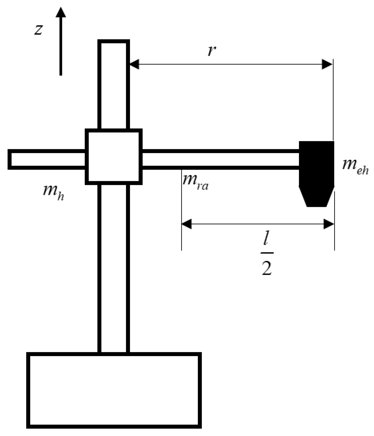
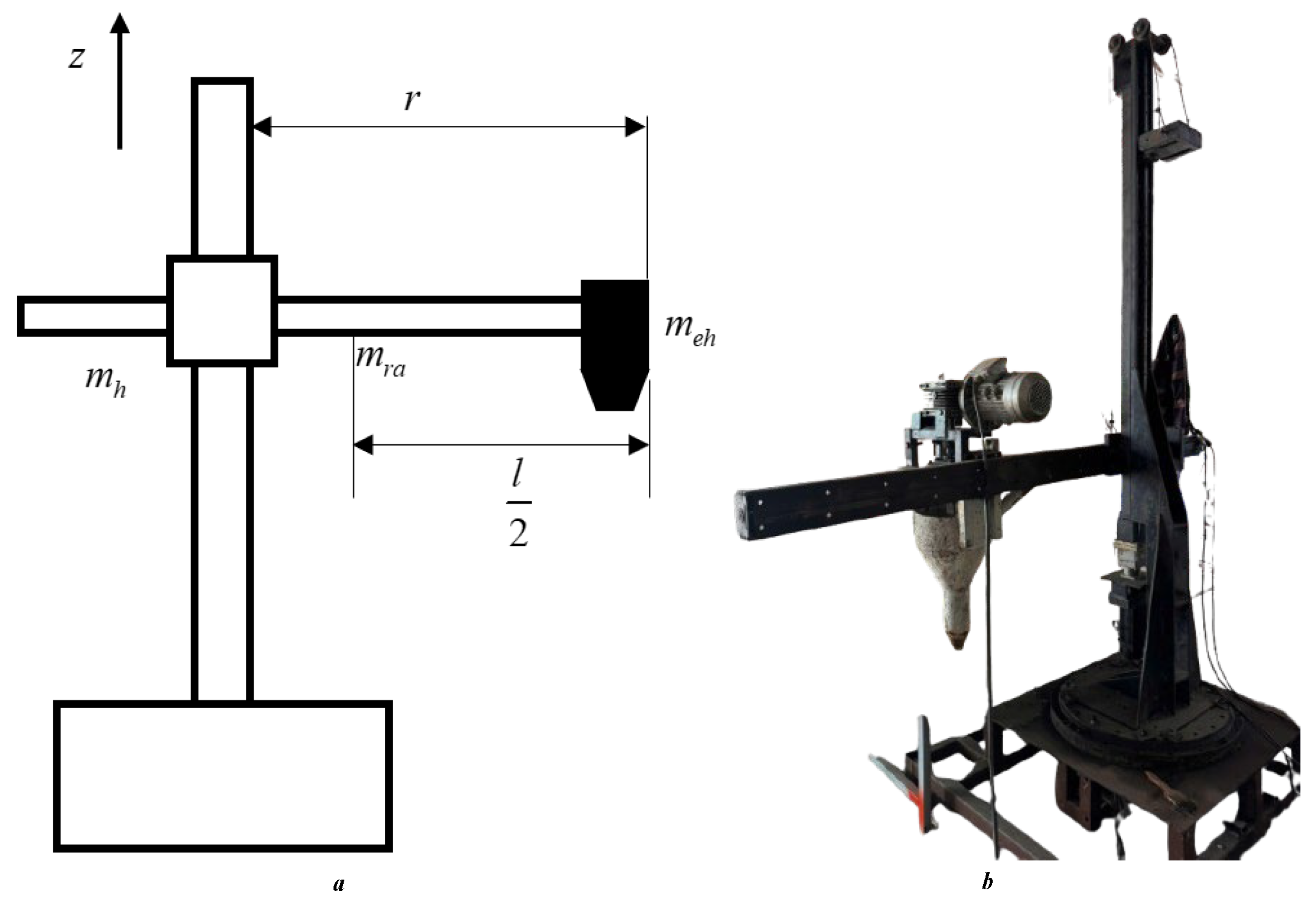
Figure 1 illustrates a 3-DoF robotic arm, where the first joint is a rotational joint about the z-axis, the second joint performs vertical translation, and the third joint executes horizontal translation, where
mh is the mass of the hub,
meh is the mass of the end-effector and
mra is the mass of the radial arm and
l is length of the radial arm. Simulating the dynamic equations for a robot is essential for design and simulation purposes to ensure that the model can function as intended. The dynamic equations provide designers with an understanding of the relationship between position, velocity, and acceleration when forces are applied to the system. The robot’s dynamics are calculated using the Lagrange–Euler method [
19]. The dynamic equations of the concrete printing robot used here are defined in Equation (1).
For the robot with three DoFs,
,
, and
are, respectively, the inertia matrix, the Coriolis and centrifugal forces, and the gravity vector, and
is the control input of torque or force vector;
are joint position, velocity, and acceleration vectors, respectively, and
d(
t) is a disturbance. Applying the Lagrange–Euler method to calculate the 3D concrete printing robot dynamic equation, the parameters of this dynamic equation are shown as (2)–(5).
where
mr mass of the radial assembly with
mr =mra + meh,
mz is the mass of vertical displacement with
mz = mr + mh,
mra is mass of the radial arm, and
meh is the mass of the end-effector (6).
The change in the moment of inertia of this link is defined by Equation (7) when the end-effector’s position is changed.
The dynamics of the robot can be rewritten as in (8).
The uncertain components in the system are present in the system because of various factors. Mechanically, varieties of uncertain components are represented as nonlinear friction at the joints, vibrations in operation, and variation in the moment of inertia. These uncertain components can cause trajectory deviations unless they are rejected. Additionally, environmental disturbances such as environmental vibrations and the variation in the frictional force of the printing surface affecting the extruder are also causes of instability in the robot’s system. Other uncertainties include errors in dynamic parameters such as mass displacement and center of gravity, inaccuracies in the calculation of the Coriolis and centrifugal matrices, sensor errors, control system delays, and unmodeled factors. This presents a significant challenge in nonlinear system control. Therefore, control algorithms must ensure the ability to compensate for these uncertainties, with sliding mode control or observers, to estimate and mitigate disturbances in real time.
In addition, the concrete extruder is considered an uncertain component in 3D concrete printing robots. The concrete extrusion process is also inherently unstable in terms of the variations in extrusion pressure, and material non-uniformity also affects the quality and accuracy of the printed concrete layers. The mass of the concrete extruder (meh) is also considered an uncertain component that needs to be evaluated. The mass of the extruder changes continuously over time because concrete in the extruder is continuously extruded and fed during the printer’s operation. Furthermore, it is important to evaluate the force acting on the extruder when the concrete is fed into the extruder and the non-uniform mass distribution of the concrete in the extruder. All of these can cause trajectory deviation in the operation of the 3D concrete printing robots.
3. Design for Chattering-Free Proportional Integral Derivative Sliding Mode Control
Sliding mode control (SMC) is highly regarded because of its properties and abilities in controlling nonlinear systems with uncertain components and disturbances. With robust disturbance rejection capabilities, although SMC does not require an extremely precise model of the system, this controller ensures that the system operates with high stability through the sliding surface principle, and SMC ensures rapid convergence time to reach the desired trajectory [
20]. Moreover, SMC efficiently handles nonlinear systems and those with complex constraints, which are often challenging for linear controllers [
21]. Its fast response time and computational simplicity make it an ideal choice for applications demanding high precision and real-time performance. However, the chattering phenomenon is the biggest problem when applying this method in practical implementations. These characteristics make SMC a compelling solution in industrial applications such as robotic control, especially in 3D concrete printing, with operating conditions that are often complex and impossible to measure. The choice of sliding surface is not only the initial step, but also the most critical factor determining the performance of the control system. The sliding surface serves as the core component that ensures the system transitions from its initial state to a stable state along the desired trajectory, regardless of the presence of disturbances or uncertainties in the model. A well-designed sliding surface guarantees rapid convergence, stability, and precise trajectory tracking. Cylindrical 3D printing robots are subjected to a variety of disturbances that can affect their performance and quality. Mechanical disturbances include vibrations and backlash in rotary joints or linear actuators, as well as instability in extended radial links due to increased inertia. Material-related disturbances caused by inconsistent material properties, such as viscosity, drying rate, and clogging in the extruder, are unmeasurable disturbances. The disturbances affect sensor inaccuracies, cause delayed feedback responses, and control system lags, leading to trajectory errors. In addition to that, external disturbances, namely ground vibrations, temperature and humidity fluctuations, and external forces like wind, further impact stability and material flow. Addressing these disturbances requires robust designs, advanced control algorithms, and rejecting the noise.
The integration of error states, integrals, and derivatives of errors into the sliding surface in sliding mode control systems leverages the strengths of both methodologies, offering a robust solution for nonlinear and uncertain robotic systems. The PID components provide essential control advantages, such as the proportional ensures rapid response to current errors, the integral term eliminates steady-state errors through accumulated corrections, and the derivative term enhances stability and mitigates oscillations [
22]. By incorporating SMC, the combined approach delivers superior robustness against disturbances and uncertainties, overcoming the limitations of traditional PID controllers. Moreover, the usage of the PID sliding surface eliminates the reaching phase, ensuring smooth and immediate convergence to the sliding surface, which improves trajectory tracking exponentially. This hybrid design simplifies parameter tuning, as in
, and maintains stability and reduces dependency on precise system modeling, making it highly effective for practical implementations. Experimental results have demonstrated that PID-SMC provides significantly higher accuracy and smoother responses compared to conventional controllers, solidifying its role as a preferred approach for complex, nonlinear robotic manipulator systems. In SMC, the sliding surface is determined as a nonlinear function with the expectation that the system will approach zero in finite time, which is set up as Equation (9). The error is defined as
e = qref − q, which is the deviation of the set angle and the actual angle of the robot. In this study, the sliding surface integrating the state error variable, the integral, and the derivative of the robot errors is defined in Equation (9).
Theorem 1. The error of the robot trajectory and the set trajectory approaches zero in a finite time if the sliding surface is selected according to Formula (9) and the control law is designed as (11)–(13).
In addition, the control law is designed to solve Equation (11), with the part of the controller chosen as (12) and (13).
Then, the dynamic equations of the 3D concrete printing robot can be rewritten as (13).
where
In this controller, the term
μS has a crucial role in enhancing control performance. It helps accelerate the system’s convergence to the sliding surface
S = 0, smoothens the control signal, and reduces the chattering effect often associated with the term. This is particularly important in mechanical systems, where chattering can lead to wear and tear or damage to components. The
μS provides a soft push force, it helps the system maintain robustness under small disturbances or against uncertainties, while ensuring a smoother control signal with less abrupt changes. The value of μ can be adjusted to balance between convergence speed and stability, with larger
μ values ensuring faster convergence but potentially causing small oscillations, while smaller
μ values result in smoother control signals at the cost of slower convergence. In nonlinear systems, stability and convergence time are the most significant challenges. Lyapunov’s theory provides a powerful framework for analyzing and designing such systems. By defining an energy-like function, known as the Lyapunov function, which tends to decrease over time, we can verify that the system’s states will converge to the desired equilibrium point or follow the prescribed trajectory. The Lyapunov criterion not only guarantees global stability but also guides the design of effective control algorithms, particularly in nonlinear systems subject to disturbances and uncertainties. For this reason, the Lyapunov theory has become a fundamental tool in the development of advanced control methods such as sliding mode control, adaptive control, etc. [
23,
24].
Proof. The stability of the system is proven by Lyapunov candidates, which means
S approaches zero, making
V approach zero in finite time. The Lyapunov candidates and derivative of the Lyapunov energy function are defined in Equation (15).
Derivative of the sliding surface (17).
Suppose that the disturbance
is bounded by
Dmax with
Dmax > 0 in Equation (19).
The coefficient
needs to be chosen sufficiently large such that the system can counteract or exceed the effect of the disturbance
d(
t), and it follows the equation. A sufficient value of
is required to ensure the sliding surface
reaches zero and ensures the system’s stability under the influence of disturbances.
The conditions for system stability are satisfied when
. When
across the entire state space, except at the equilibrium point
S = 0, the system is considered asymptotically stable, meaning the state
S converges to zero. Using Equations (18)–(20), the derivative of the Lyapunov function can be rewritten as (21).
□
Let
ts be the time when s reaches 0 from time
to; the convergence time of the system is calculated as in Formula (22).
The PID sliding manifold is designed according to Equation (17), adjusting the parameters
μ1,
μ2, and
μ3 to change the mechanical characteristics of the system. The natural oscillation frequency of the system
ωn, and the damping factor
ξ are chosen to simplify the calculation processes of the system. With
ξ = 1, the desired characteristic equation
. The coefficients are selected based on the natural oscillation parameters and the damping factor as follows (23):
4. Results and Discussion
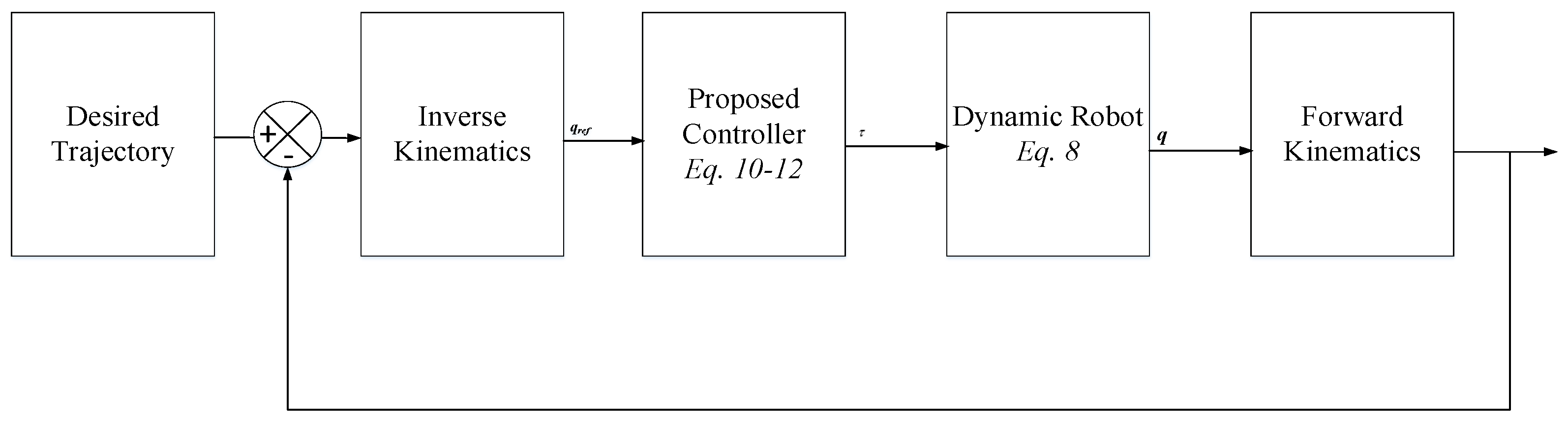
To ensure accurate trajectories for the concrete 3D printing robot, the controller is calculated to counteract disturbances caused by various factors. The closed-loop control structure diagram of a concrete 3D printing robot with three degrees of freedom is shown in
Figure 2. The desired position is compared with the actual position of the robot, which is measured by the position sensor. The error between the desired and actual trajectory is fed into the PID-SM controller, which adjusts the control signal to ensure that the robot accurately tracks the set trajectory. This controller sends the signal to the concrete 3D printing robot system, which controls the three degrees of freedom to reach the desired trajectory. Concrete 3D printing robots operate under constantly changing load conditions. The process of continuously adding concrete to the extruder causes its mass to change, which makes it difficult for controllers to follow the placement trajectories. In concrete printing robots, trajectory errors play an important role because the structures are built based on the principle of stacking with overlapping prints. In this study, the robustness of SMC is desirable for developing and eliminating chattering to apply the algorithm in practice.
To validate the effectiveness of the proposed control algorithm, simulations are conducted using MATLAB Simulink 2023a with a sampling time of 0.002 ms. We consider the conventional sliding mode control (SLM) with the sliding surface and control algorithm as Equations (24)–(27).
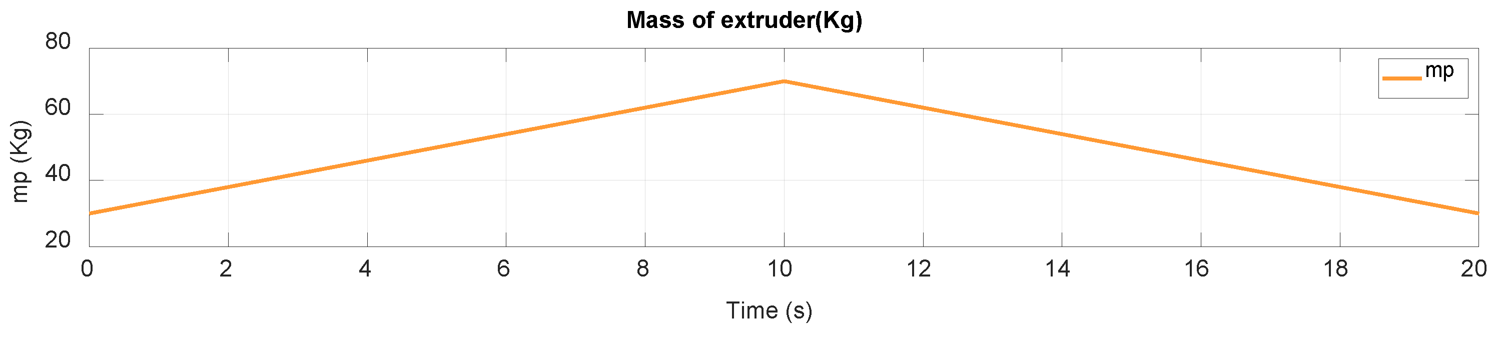
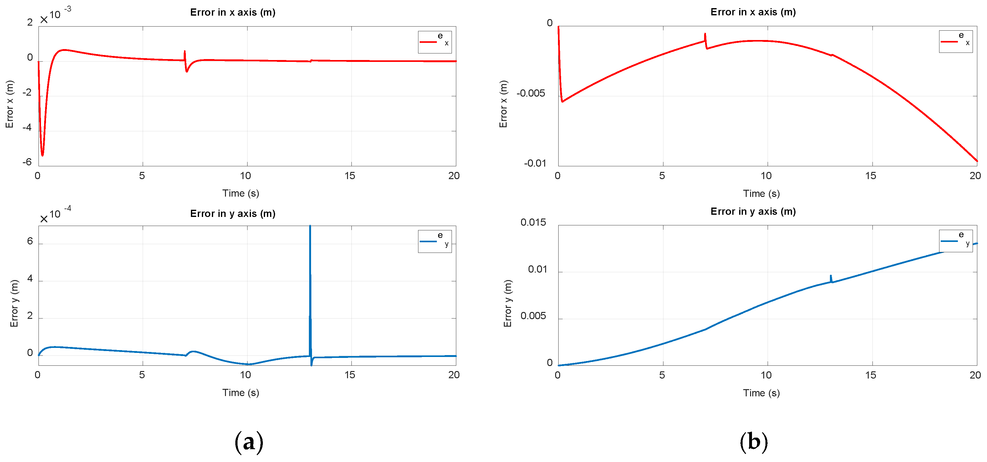
The simulation is designed to replicate the dynamic behavior of the robotic manipulator under various operating conditions. The proposed controller is implemented in MATLAB Simulink, and its performance is evaluated by analyzing the accuracy of trajectory tracking and robustness against disturbances. The trajectory tracking for the end-effector is presented in this section. The simulation is performed in 20s with a trajectory consisting of two straight lines and a curve, and the continuous change in extruder mass as seen in
Figure 3. The results of trajectory tracking, the errors in the X axis and Y axis, are shown in
Figure 4 and
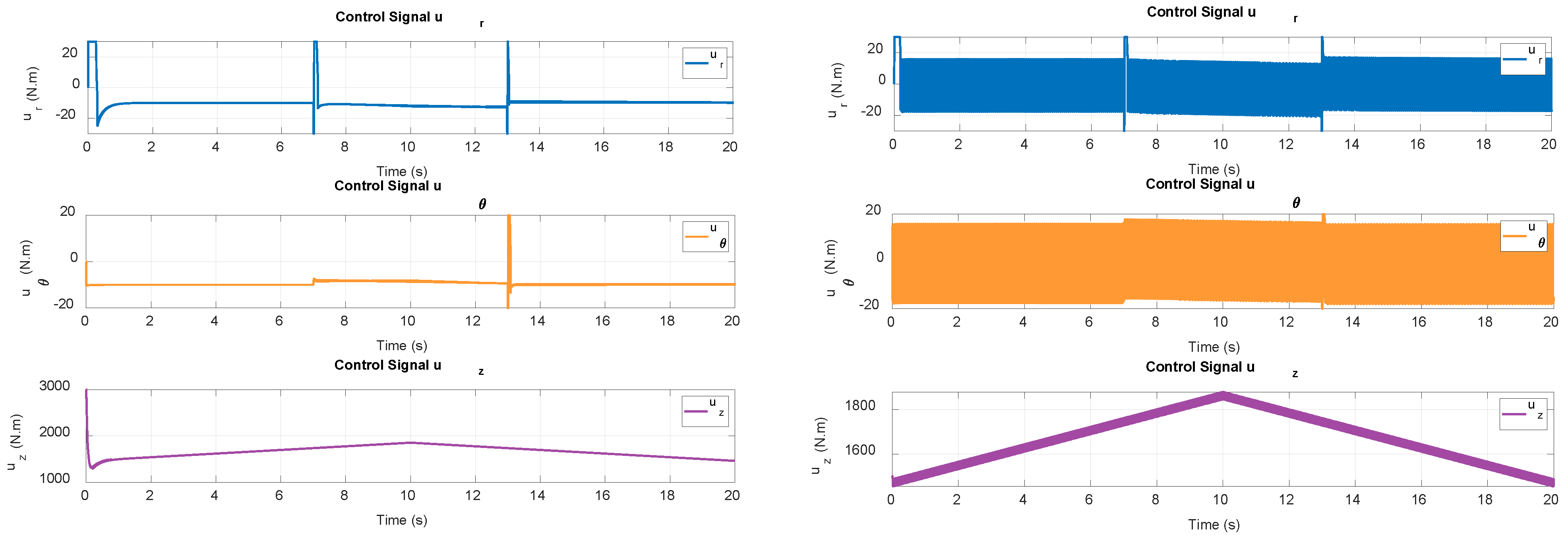
Figure 5, and the control signal is shown in
Figure 6.
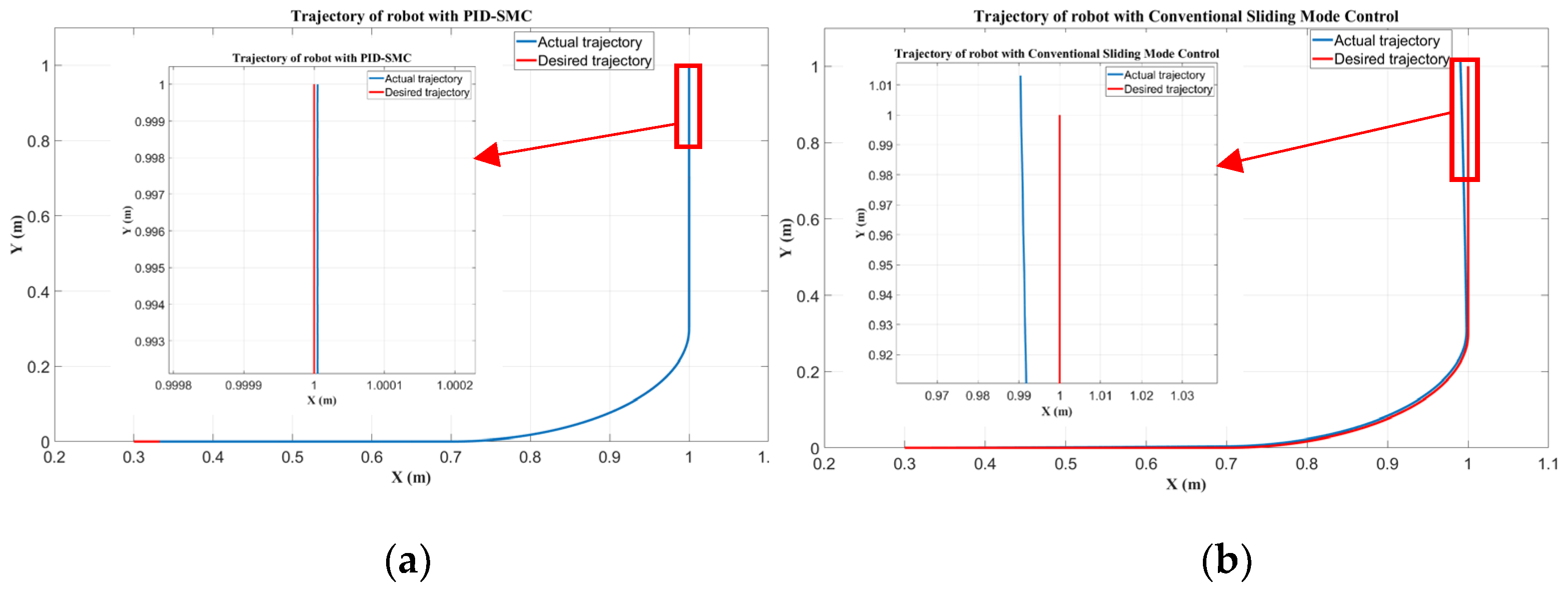
The simulation results show that the actual trajectory closely tracks the desired trajectory. The robot’s trajectory is smooth, and there is no chattering phenomenon in the robot’s trajectory. The error of trajectory is negligible and gradually decreases to zero. The controller ensures long-term system stability. In the simulation results, the trajectory error increases slightly when the robot trajectory changes suddenly or is affected by a disturbance, but the controller quickly reacts to the disturbance and makes the system reach a stable state again. The control signals of the three robot stages are stable and do not cause chattering, which ensures durability and limits mechanical wear on the system. The PID-SMC controller guarantees fast convergence times, high stability, and good disturbance rejection capability for the robot system. The controller ensures that the concrete 3D printing robot tracks the desired trajectory with only slight error. Considering the concrete 3D printing robot, this system is subjected to a large load from the extruder due to the constant change in extruder mass during the printing process over time. In addition, the system is also affected by other nonlinear components such as friction, gravity, and Coriolis. With the simulation results, the PID-SMC controller shows its potential when applied to such systems. The PID-SMC controller also demonstrates good disturbance rejection and achieves high efficiency when handling complex trajectories. The proposed control algorithm ensures smooth movement of the robot arm, limits chattering, and ensures the quality of the printed object is uniform and consistent.
Based on the simulation results, the trajectory with the conventional sliding mode controller has a higher trajectory tracking error than the PID-SMC controller. When using the conventional sliding mode controller, the system has a sluggish response to disturbances or sudden changes in the trajectory. In addition, the control signal, when using the conventional sliding mode controller, has too much chattering, which adversely affects the system, as chattering causes wear and damage to the system. From the comparison results between the two algorithms, the PID-SMC control algorithm delivers superior performance in significantly reducing trajectory tracking error, the system quickly reaches a stable state after disturbances or sudden trajectory changes, and it significantly reduces the chattering of the control signal. The 3D concrete printing robot is introduced in
Figure 7, including in design, and the actual robot.


