Article

Finite Element Analysis (FEA) for the Evaluation of Retention in a Conometric Connection for Implant and Prosthesis

1
Department of Mechanics, Mathematics and Management, Polythechnic University of Bari, 70125 Bari, Italy
2
Private Practice San Vendemiano, 31020 Treviso, Italy
3
Department of Medical, Oral and Biotechnological Sciences, “G. d’Annunzio” University of Chieti-Pescara, 66100 Chieti, Italy
4
Center for Advanced Studies and Technology (CAST), “G. d’Annunzio” University of Chieti-Pescara, 66100 Chieti, Italy
5
School of Dentistry, Saint Camillus International University of Health and Medical Sciences, 00131 Rome, Italy
6
Facultad de Medicina, UCAM Universidad Católica San Antonio de Murcia, 30107 Murcia, Spain
*
Author to whom correspondence should be addressed.
Osteology 2023, 3(4), 140-156; https://doi.org/10.3390/osteology3040015
Submission received: 19 September 2023 / Revised: 12 October 2023 / Accepted: 28 November 2023 / Published: 4 December 2023

Abstract

:
Today, dental implantology represents a reliable technique for treating both partial and total edentulism. The fixation of dentures on dental implants can be achieved using various techniques, where the choice of a specific technique depends on the patient’s individual needs, the jawbone’s condition, and the prosthesis design. Currently, the two most common types of prosthetic abutment connections are cemented and screwed, each with its own set of advantages and disadvantages. This study aimed to analyze a novel Morse cone connection system between the prosthesis and implant using finite element analysis (FEA). The analysis of connection retention was conducted using three different approaches: analytical, in vitro, and FEA. Three-dimensional models were created for systems comprising an abutment, healing cap, and crown under three inclination conditions: 0°, 15°, and 30°. Using Ansys finite element software (R1 2023), the impact of the tilt on the system retention was examined. The FEA showed results comparable with the in vitro studies regarding the retention strength for an abutment cap system with a 4° taper, obtaining 66.6 N compared with the 68 N calculated in our in vitro study. The inclination of the abutment affected the system retention due to the hole made in the abutment’s surface, decreasing the contact area between components. The Morse cone prosthesis–implant connection system was found to be the most stable and efficient compared with threaded or cemented systems. The retention was influenced by factors such as the abutment conicity, insertion strength, and the contact surface between components.

1. Introduction

Implantology can be considered a safe method for addressing issues of partial and total edentulism, particularly in patients of advanced age [1,2]. As the primary objective in selecting implant materials is to ensure the safety and functionality of patients, the current literature survey explores and highlights key aspects related to the mechanical, biological, and microstructural properties of biomaterials used in dental composites or implants. Therefore, numerous efforts have been made to enhance the clinical performance of dental materials, particularly focusing on the physical, mechanical, and thermo-mechanical characteristics, including void content, hardness, compressive strength, and bending strength, especially in the case of dental resin-based composites since their inception. Indeed, while metal–ceramic restorations have long been the benchmark in implant dentistry, the landscape has evolved to include metals, polymers, ceramics, and composites as the four main types of dental restorative materials. However, zirconia is now in the spotlight as a promising option for restoration due to its highly favorable mechanical properties and satisfactory aesthetics [3,4].
Furthermore, in modern implantology, there are two diverse types of implant prosthesis support, which depend on the number and position of the implants. Treatment options include fixed or removable implant–prosthesis support. The removable prosthesis implant support consists of a prosthesis anchored to the implant with diverse fixation methods: screwed or cemented. However, both fixation systems have some disadvantages [5]. Although cemented fixation seems ideal, the drawback lies in having to eliminate excess cement in the soft tissues around the implant structure. Some studies linked residual cement to the development of chronic peri-implant diseases, as it can cause soft tissue inflammation and relative resorption of the bone crest. Another issue is the removal of cement if the margins are located sub-gingivally. The greater the depth, the more challenging it is to detect excess cement [6,7,8,9,10,11,12]. On the other hand, a screwed connection involves greater complications, where inadequate preload of the screw, misfit between the interface of the two components, and the characteristics of the screw are considered reasons that lead to the loosening of the screw or even fractures [13,14].
Among prosthetic abutment connections, the external connection usually has an external hexagon on the implant platform, whereas the internal connection can be divided into an internal hexagon, internal octagon, and Morse cone, which is currently being used extensively [15]. Stephen A. Morse pioneered the development of this connection in 1864, which has since found global application for connecting drilling machines to a removable rotating drill piece [16]. The fundamental concept of this system is based on the “cone within a cone” principle. This connection involves coupling two surfaces with identical conicity: an abutment (male) and a cap (female) that interlock without the need for screws or concrete [17]. It is also worth mentioning that the Morse cone implant accepts different abutment platforms and provides an intimate implant–abutment contact [16]. This type of connection presents an interesting alternative due to its advantages compared with cemented or screwed connections, such as a reduced bacterial microleakage at the implant–abutment surface; fewer mechanical complications, like screw loosening or fractures; higher torque preservation; and fixed retention between implants and dental prostheses [17,18,19] (Figure 1).
When force is applied externally, retention occurs due to the friction formed between the two surfaces [20]. Upon analyzing the conometric connection system, it is evident that the configuration of the abutment influences its retentive ability. A study conducted by Nardi et al. in 2017 [21] indicates that the greater the diameter at the base and height, the higher the retentive ability. Applying an external force in the direction coinciding with the axis of insertion of the cap generates stress and deformation fields that affect both the inside of the cap and the abutment. These stress fields persist even after the removal of the insertion force and it is precisely these stress and deformation fields that contribute to the retentive ability of the system.
Some studies revealed an inverse relationship between the retentive force and the taper angle of the cap [22,23]. Bozkaya and Muftu [22] performed a numerical–mathematical evaluation to assess the efficiency ( η ) of the Morse cone connection, which is defined by the ratio of extraction force (Fout) to insertion force (Fin) shown in Equation (1):
η = 2 cos θ μ k μ k cos θ sin θ
For a stable cap-to-abutment connection, the efficiency must exceed 1, indicating that the extraction force is greater than the insertion force, preventing spontaneous loosening. Referring to the study by Bozkaya and Muftu [22] and considering Equation (1), it was observed that the efficiency is influenced by the taper angle and the coefficient of friction between the surfaces. Therefore, an increase in the taper angle or coefficient of friction leads to decreased efficiency [23]. In this regard, findings reported by Prisco et al. [23] suggest that for system stability, taper angles should be less than 6° and the friction coefficient should be around 0.3. As previously explained, retention is guaranteed by the presence of an adequate stress field in the absence of an applied load. It is crucial to note that for the system to be efficient, the stresses induced by the cap insertion must not exceed the material’s yield strength [24].
Another crucial aspect to consider involves the insertion force, which, owing to the conical geometry of the system, generates contact pressures at the abutment–cap interface, resulting in a normal force (N) as per Equation (2) [22,23,24]:
N = π E Δ z L c sin 2 θ 6 b 2 2 3 b 2 2 r a b 2 L c sin θ 3 r a b + L c sin θ
This formula reveals the insertion force dependence on the taper angle ( θ ) and the length of the surfaces in contact ( L c ) in a linear manner for contact lengths from 1 to 5 mm [24].
From these initial observations, it becomes evident that the insertion force of the cap plays a fundamental role in defining the stability of the system. First, this force must be sufficient to securely seat the cap, providing resistance to extraction forces. Second, it should prevent excessive plastic deformation of the cap and abutment due to interference. The analytical method used to detect this force has limitations because it is obtained under stringent restrictions. Cyclic loads from mounting and dismantling the cap, leading to surface erosion phenomena and, consequently, decreasing the retention of the system, are not considered [24,25]. On the other hand, in vitro studies established that the connection exhibits varying retention based on the taper angle: 40.36 N for a taper angle of 6° and 235 N for an angle of 1° [26].
The advantage of using finite element analysis (FEA) compared with other methods is that many factors influencing system retention can be evaluated simultaneously in less time. Moreover, when comparing in vitro studies with the finite element method (FEM), we can presume that the former is a destructive procedure, as it involves breaking the device to find the resistance limit, while the latter has the advantage of being a non-destructive technique. Thus, the aim of this study was to assess, using the FEM, the force required for cap insertion into a conometric connection of 4° taper between the abutment and cap. Additionally, we aimed to investigate the impact of abutment inclination (15° and 30°) on system retention. Then, we also compared the FEA results with the analytical findings from Bozkaya and Muftu [22] and experimental data from Antonaya-Martin et al. [26] to determine the most suitable method. The null hypothesis assumed that the abutment inclination and presence of a hole on the abutment surface (Figure 2) for inserting the retention screw do not affect the system’s performance.

2. Materials and Methods

A FEA study involves the following steps:
  • Model creation: Start by digitally modeling the structure or part to be analyzed. This model is divided into smaller parts known as finite elements. Finite elements are simple geometric shapes, such as triangles or quadrilaterals in two dimensions 2D and tetrahedra or hexahedra in three dimensions 3D.
  • Definition of material properties: Each finite element is assigned material properties, including Young’s modulus, Poisson’s coefficient, strength, and other characteristics depending on the material of the part.
  • Application of loads: Define loads, such as forces, moments, pressures, constraints, and boundary conditions, to simulate the real environment in which the structure operates.
  • Discretization: The model is divided into finite elements, and the nodes of these elements are assigned unknown variables like displacements, stresses, or other relevant quantities. Subsequently, the load/constraint conditions are assigned, and the results are analyzed.
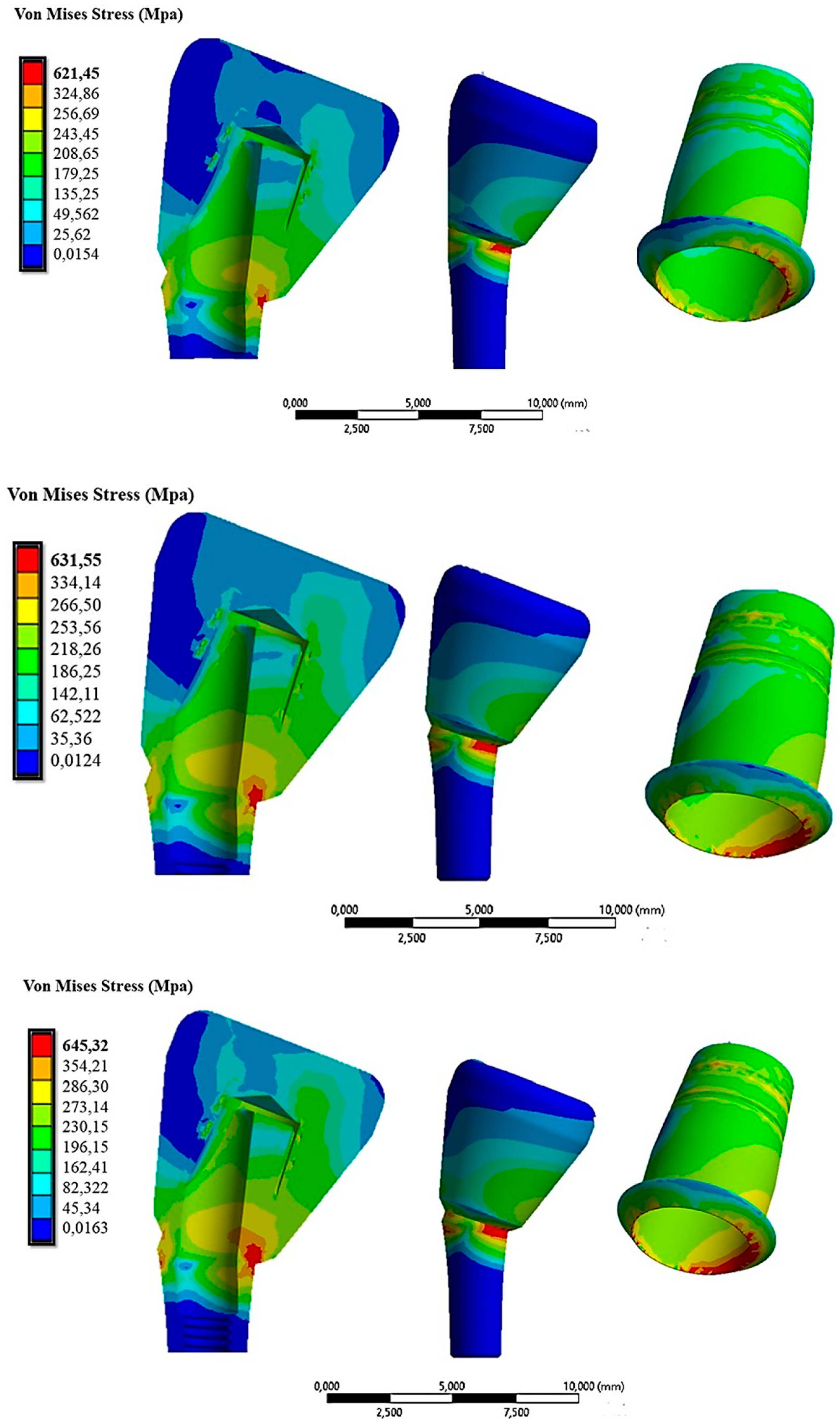
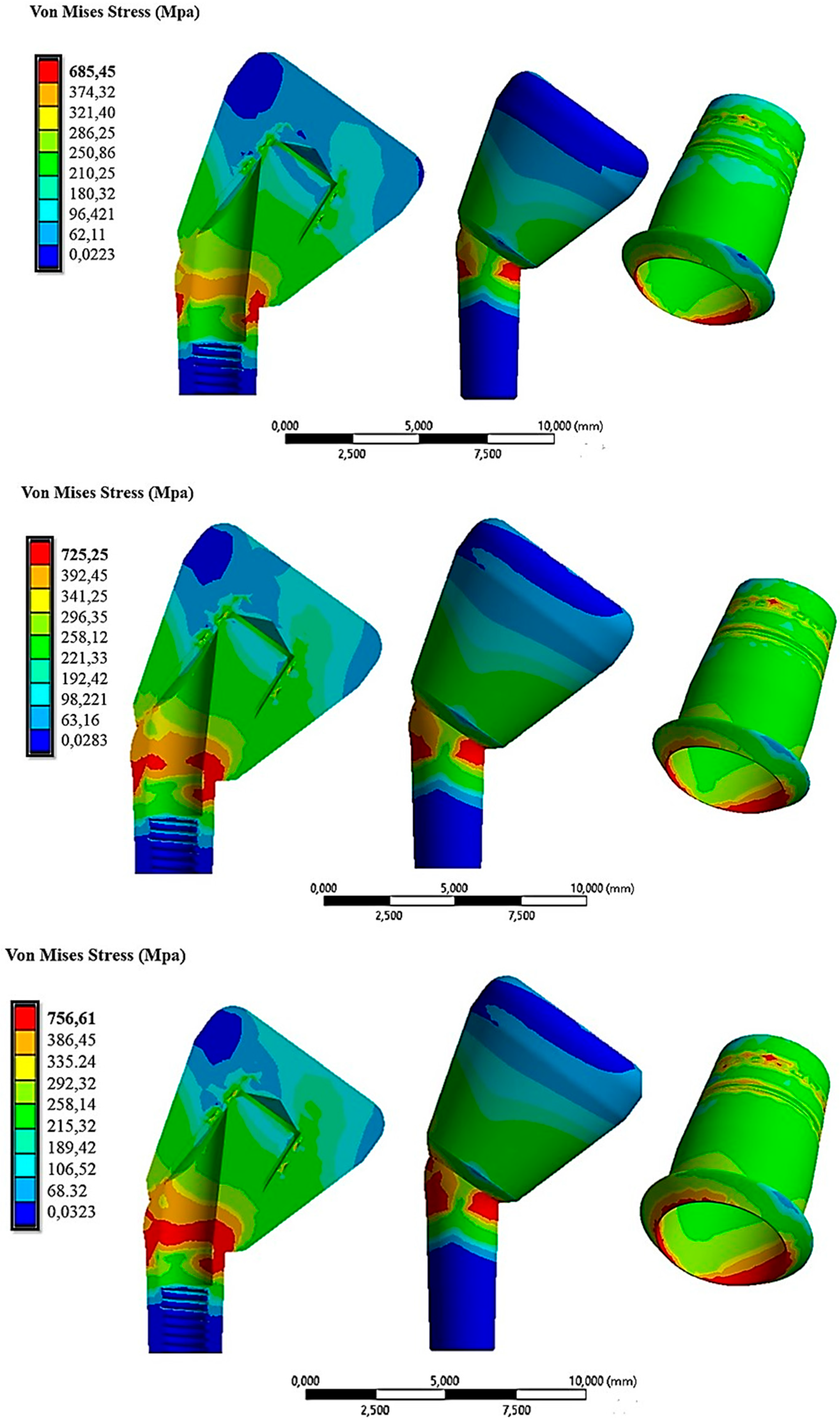
In the present study, three different systems, consisting of the abutment, the cap, and the crown of the AoN implant (AoN Implants, Grisignano di Zocco, Italy) were modeled using Autodesk Inventor 3D modeling software (Autodesk Inventor 2023, San Francisco, CA, USA). Figure 3 shows the abutment–cap–crown system in the 0° tilt configuration, while Figure 4 displays the 15° and 30° configurations of the cap–abutment system.
Subsequently, the 3D models were imported into ANSYS 2023 finite element software (ANSYS R1 2023, Workbench, Canosburg, PA, USA). FEA was employed to analyze the stress distribution on the cap–abutment system during cap insertion. Thus, the virtual models were converted to a .stp format, which is readable by the FEA software ANSYS. The implemented geometry did not consider the implant since the focus of this study was on the cap–abutment connection zone.
The cap–abutment model was discretized using Solid 187 4-knot tetrahedral elements using a 0.5 mm mesh [27]. At the abutment–cap contact, to better appreciate the stress distribution, the mesh was refined to 0.3 mm (Figure 5).
After modeling the finite elements of the system, the properties of the materials used in this study were assigned. All materials were assumed to be homogeneous, linear, and isotropic, as the von Mises criterion used to analyze the results was based on these considerations [28]. The properties of the materials are shown in Table 1 [18,29].
To analyze the cap–abutment system, various contact modes between the two components were assigned, as illustrated in Figure 6.
Between the crown and the cap, a fixed type of contact without penetration was imposed. The contact analysis assigned the cap as the target element, indicated in red (Figure 7), referring to finite elements in the FEA that were considered particularly important or relevant to the analysis aim. Conversely, the “contact elements” modeled the contact surfaces between the parts and are shown in blue (Figure 7).
The abutment was fully constrained, with constraints applied to its side surface, as shown in Figure 7. On the upper surface of the zirconia crown, a vertical static load was applied along the direction of cap insertion, with variable intensity ranging from 10 N to 60 N. For this load, we used the cap insertion loads obtained from in vitro studies as a reference [31].
For the analysis of the results, three methodologies were employed in this study to determine which one provided reliable results. The first method used was an analytical approach proposed by Bozkaya and Muftu [22], with the aim to calculate the retention force of the cap with knowledge of parameters related to the taper and coefficient of friction. Using Equation (1), the following data could be assumed: θ = 4° and μ s = 0.3 = μ k . The system’s efficiency could be calculated using Equation (3):
η = 2 cos θ μ k μ k cos θ sin θ = 1.52
The second method used was an experimental approach proposed by Antonaya-Martin et al. [26], where a graph obtained using in vitro tests was employed to calculate the system’s retention, knowing only the abutment’s conicity (Figure 8).
The third method employed was the FEA proposed in this study to compare the results. From the application of the cap insertion load, we could evaluate both the von Mises stress distribution and the axial displacements of the cap ( Δ z ) along the insertion direction. Using Equation (4), the retention of the system could be calculated:
F r = π E Δ z L c sin 2 θ 6 b 2 2 3 b 2 2 r a b 2 L c sin θ 3 r a b + L c sin θ
The necessary data for the calculation could be obtained from the 3D model developed with the company AoN Implants (Grisignano di Zocco, Italy): r a b = 1.414 mm, b 2 = 1.850, L c = 5 mm, θ = 4°, and μ s = 0.3.
After modeling with ANSYS software, von Mises stress values were evaluated for both non-angled and angled systems at 15° and 30°. Stress distributions are represented by color-coded maps, with the maximum stress in red and the minimum stress in blue for the qualitative analysis.

3. Results

Figure 9 shows the von Mises stress distribution on the abutment–cap–crown system under an insertion load of 10 N.
The von Mises stress ranged between 0.0032 MPa and 506.01 MPa. The maximum stress values were found on the cap due to its thinness, resulting in increased stress. Figure 9 also shows stress values ranging between 35 MPa and 120 MPa in the area of contact with the cap on the zirconia crown. This stress field did not impair the mechanical behavior of the material since, as described in Table 1, the breakdown stress of zirconia is approximately 551 MPa. In Figure 10, the displacement field in comparison with the cap is shown because the abutment was fixed in all directions.
From Figure 8, we observe that the cap had a field of displacements that varied along the axial direction. In fact, the maximum values were reached in the lower part of it (red zone in Figure 10), where there was approximately 0.00273 mm of displacement. This value was also comparable with the results of the FEA study conducted by Bressan et al. [32].
Figure 11 demonstrates the stress distribution when the cap was inserted with a force of 30 N and 60 N.
Here, it could be observed that as the cap insertion force increased, there was a corresponding increase in the stresses on the system. Specifically, it rose from about 511.73 MPa with a 30 N insertion force to 594.08 MPa with a 60 N insertion force. From this initial analysis, it was evident that the most stressed part was the cap at 594.08 MPa, especially considering it was a crown made of zirconia, which is a material capable of transferring all applied forces. This stress value, however, did not compromise the mechanical behavior of the cap, as its resistance to yield strength is about 830 MPa (Table 1). Nevertheless, exploring alternative materials might be worthwhile to assess any reduction in transmitted stress. Additionally, Figure 11 shows that the abutment experienced higher stresses in the case of a 60 N cap insertion. The circumferential stresses generated by this force increased the compressive stress on the outer surface of the abutment. Table 2 summarizes the results obtained in terms of the von Mises stress and displacement along the z-axis of the cap for insertion loads ranging from 10 N to 60 N.
Table 2 demonstrates that with an increase in the insertion force, there was a corresponding rise in both the displacement of the cap and the von Mises stress. It could be asserted that there were no critical issues in the system, as the yield strength of the material, which is 830 MPa for titanium, was never exceeded. By knowing both the insertion force and the vertical displacement of the cap, we could calculate the retention force for each cap load condition using Equation (2) and obtain the orange line in Figure 12.
Using the analytical method proposed by Bozkaya and Muftu [22], the blue line was obtained (Figure 12). It could be observed that the analytical method, owing to the multiple simplifications made in the geometry, yielded lower values of removal force as a function of the insertion force.
Instead, when examining the experimental method proposed by Antonaya-Martin et al. [26] for a cap insertion load of 30 N, it corresponded to a removal force of approximately 70 N (Figure 13).
Among the three criteria presented, it was noticed that the FEA approach provided results closer to the values obtained experimentally through in vitro studies. Specifically, for a cap insertion force of 30 N, the FEA method yielded a retention force of approximately 66.3 N, while the analytical method produced 45.78 N, compared with the in vitro study value of 68.8 N.
The time effect of tilting was studied using the same load data as mentioned earlier. Figure 14 shows the distribution of the von Mises stress when the cap was inserted with loads of 10 N, 30 N, and 60 N in the 15° configuration.
From Figure 14, it was evident that the 15° inclination of the abutment resulted in increased stress on both the abutment and the cap. Specifically, in the red areas, the maximum stress varied from 621.45 MPa with 10 N of insertion to 645 MPa with 60 N of insertion on the cap.
Figure 15 illustrates that the von Mises stress distribution was higher compared with the case with a 15° inclination.
This was attributed to the inclination, which involved a decomposition of forces along the direction perpendicular to the axis of cap insertion. These tangential forces stressed the abutment more. In the configuration of 30° with a cap insertion force of 60 N, stress values of about 756 MPa were recorded on the abutment and the lower part of the cap (Figure 15, third line). Consequently, we could assert that the abutment configuration inclined at 30° experienced higher stresses compared with the 15° and 0° configurations. By exclusively analyzing with the FEA method, we could calculate the retention of the system in configurations with inclined abutments and compare it with the non-inclined abutment configuration (Figure 16).
Figure 16 demonstrates how the retention decreased with the inclination in the abutment at the same insertion force. For instance, assuming that the cap was inserted with a force of 30 N, we observed that in the case of no inclination, we had 66.3 N, whereas it decreased to 57.018 N for abutments inclined at 15° and further reduced to 53.04 N for abutments inclined at 30°. This phenomenon occurred because the hole for the insertion of the retention screw reduced the amount of surface available for contact with the cap, resulting in a decrease in the retention ability of the system. Consequently, to achieve the same retention as required by in vitro studies, or approximately 70 N, it would be necessary to increase the insertion force by about 10 N more than the non-inclined configuration when dealing with inclined abutments.

4. Discussion

In previous studies, CAD/CAM technology was employed as an investigative technique in vitro. Notably, a study by Kapos and Evans [31] demonstrated that the use of a screwed implant prosthesis retention system resulted in lower stress compared with the conventional cement-based system. This phenomenon is attributed to the presence of multiple separate components in the screwed system, including the implant, abutment, prosthetic screw, and crown. The existence of micro-gaps does not ensure a uniform stress distribution among these components and the implant. Consequently, it was concluded that cemented retention systems exhibited higher stresses and deformations. Also, photo-elastic studies [32] confirmed this phenomenon, revealing that the gap between implant components can either reduce or increase the stress transmitted to the bone due to micro-movements. While the use of a screwed retention system may lead to bone resorption due to insufficient stress transmission, a cemented connection allows the stress generated by the masticatory loads to discharge directly onto the bone rather than being dissipated among prosthetic components. These factors can elevate stress on the bone, potentially resulting in resorption. Indeed, a study by Aalaei et al. [33] demonstrated that when the stress generated in the crestal area of the implant exceeds the elasticity of the bone, microfractures and resorption occur. Although screwed prosthetics offer the advantage of removal without damaging the denture or implant, the only drawbacks lie in the aesthetic problems and fracture risks associated with creating a hole in the crown for screw insertion.
With the conometric system, dental prostheses can alleviate pressure on the surrounding gum tissue, helping to prevent long-term damage or irritation. Specifically, scanning electron microscopy (SEM) analyses were conducted on the interface between the cap and abutment, revealing that even after the application of the load, no significant gap was observed [34]. This yields several benefits, including a reduced risk of bacterial infiltration and more evenly distributed stress. In the conometric connection, retention is achieved only through the frictional force developed at the abutment–cap interface. A perfect fit between the two surfaces and the absence of a marginal gap in the conometric connection are fundamental requirements to avoid failures and bacterial infiltration [35,36]. In attempts to further minimize inflammatory responses and enhance bone stability in the crestal area of the implant, numerous in vitro studies emphasized that a gap between the abutment and cap (2.04–2.064 µm) is necessary to prevent bacterial infiltration [37,38,39]. In contrast, a cemented connection between the abutment and cap was found to have a larger gap (145 µm) [39]. Another consideration relates to prosthesis removal. A study by Degidi et al. [40] demonstrated that prostheses utilizing a conometric retention system were easily removed. Conometric prostheses are designed for easy removal and cleaning, simplifying oral hygiene and prosthesis cleaning compared with cemented or adhesive dentures, which often face challenges related to incomplete cement removal. The success rate of conometric prostheses is a critical aspect of rehabilitation. Numerous studies have reported a 97.77% success rate during a 2-year follow-up period [41,42,43]. System retention, which is understood as the ability of the prosthesis to remain stable and firmly in place during normal use, is a key factor in long-term durability. As mentioned earlier, the retention of the conometric connection depends on the initial load during cap insertion, taper angle, height, and friction between the two surfaces [22,23,24,44,45]. Insufficient retention can result in prosthesis loosening, leading to implant problems and bacterial infections. The impact of cap insertion–separation cycles on retention ability has been evaluated in numerous studies [25,46,47]. In particular, an in vitro study demonstrated that retention decreases by about 40% from 5 to 15 insertion–removal cycles [48]. This phenomenon is attributed to variations in the functional characteristics of the surfaces in contact with an increase in the number of cycles. Additionally, retention diminishes if the plastic limit of the material is exceeded, as the state of residual stress necessary for retention is no longer guaranteed. However, when similar materials are used, cold fusion can develop between the abutment–cap contact surface, ensuring greater retention. Conversely, with a softer material than the abutment, there is more wear on the inner surface of the cap, resulting in less retention [49]. In the oral environment, prostheses are subject to time-varying chewing forces, temperature variations, and high humidity, which are factors that worsen cement conditions, causing a loss of retention. A study by Al-Chalabi et al. [50] measured the retention of a cemented and conometric system, highlighting that the use of the conometric system led to increased retention due to the phenomenon of cold welding between the two components. In contrast, the cemented system exhibited a decrease in retention after 5 years due to the loss of cement performance.
The assessment of cap–abutment connection retention has traditionally been conducted through in vitro studies. Notably, research by Ghodsi et al. [51] revealed that the retention varies with the conicity of the abutment, ranging from 40.46 N for a 6° taper to 235 N for a 1° taper. In dentistry, the FEA method, as demonstrated in this study, has also been applied in other research to investigate the effects of different connection types on stress in the implant and surrounding bone under various loading conditions, both static and dynamic [18,29,33,34,52,53,54,55,56]. Bressan et al. [57] used the FEA method to analyze the retention of a Morse cone connection. Their findings indicate an in vitro retention of 148.22 N with a gold cap compared with 150 N obtained through numerical analysis. However, there is a lack of clear data in the literature regarding the minimum retention required for the crown and cap to remain in a stable position. During chewing, the depressor muscles exert displacement forces on the prosthesis. Therefore, the minimum retention force must exceed the contraction force of these depressor muscles, which is approximately 113 N [58,59]. A numerical study contributed to the development of a mathematical model that qualitatively assesses the retention offered by the system based on conicity [60]. Notably, the model shows that the retention increases exponentially with a decrease in the taper angle. The other method for evaluating system retention is through numerical simulation, particularly FEA. Widely used in engineering and medical applications, FEA allows for an accurate simulation of the mechanical behavior when the cap is inserted into the abutment. The process implemented in this study enabled the evaluation of system retention for an abutment with a 4° taper and the determination of the required force for cap insertion to obtain sufficient retention. The FEA also facilitated the assessment of the effect of abutment inclination on retention.
Contrary to the null hypothesis, an inclined abutment created a hole for screw insertion on the mating surface, decreasing the surface in contact with the cap and, consequently, reducing the retention ability of the connection. Additionally, the retention decreased with an increased angle of abutment inclination, as axial loads along the abutment were broken down into mesial, distal, and buccal components, which, with inclination, acted as a lever on the cap, further diminishing the retention of the system.

5. Conclusions

In conclusion, the finite element simulation conducted in the present study allowed us to derive the following results:
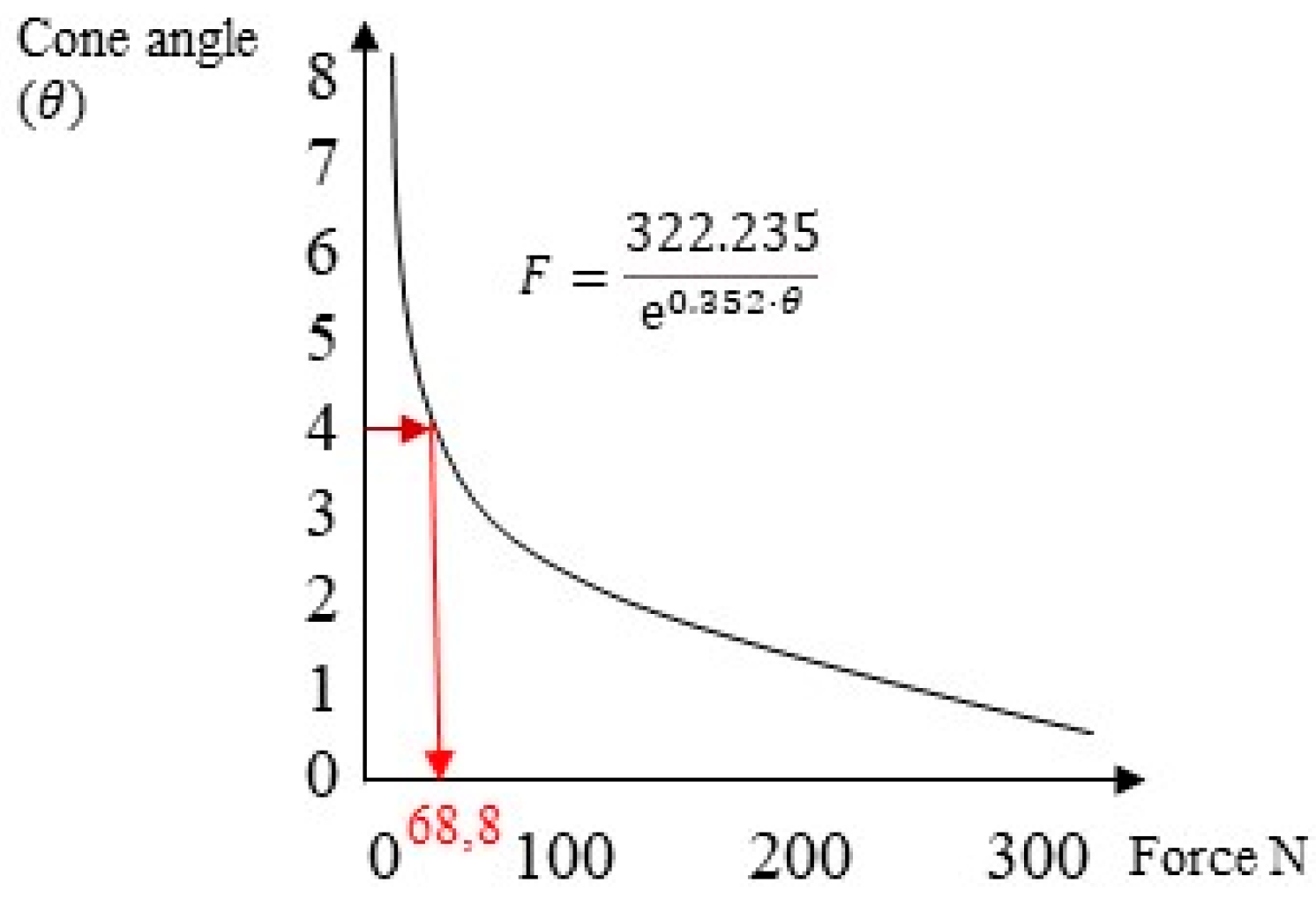
  • There existed a linear relationship between the cap activation force and retentive force.
  • The analytical method proposed by Bozkaya and Muftu [19] underestimated the system retention.
  • The FEA method demonstrated comparable results with in vitro studies. For a connection with a 4° conicity, the retentive force obtained from in vitro studies was 68 N, while with FEA, it was 66 N.
  • The force required to activate the connection in the case of a 4° taper was approximately 30 N. Values below 20 N of activation force did not guarantee the required retention.
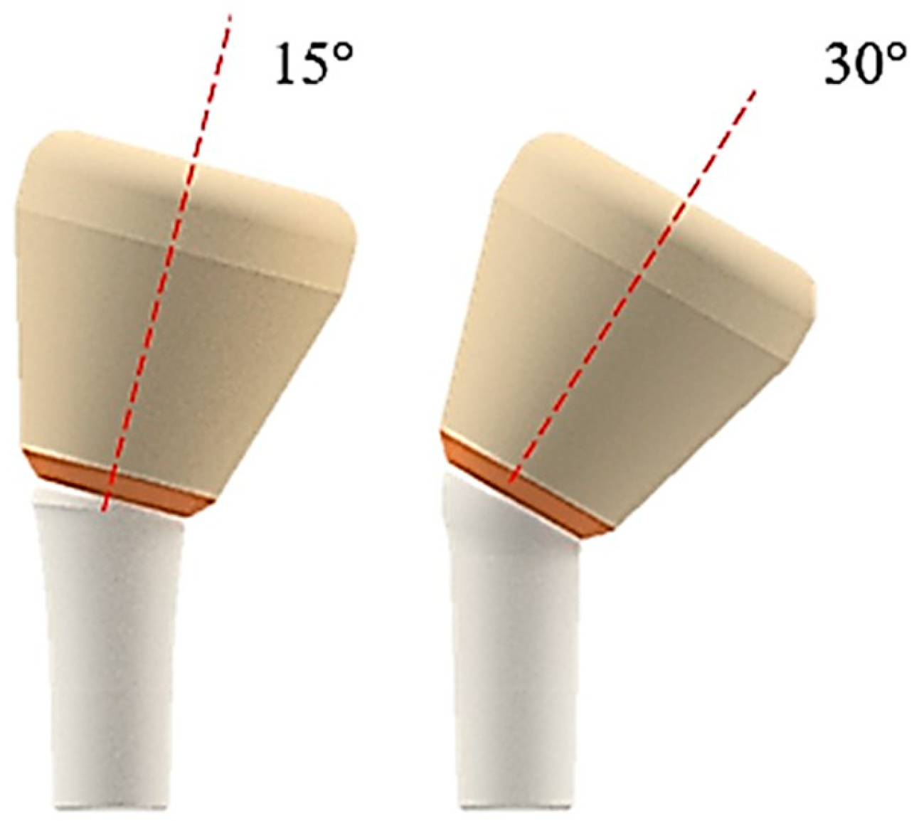
  • The inclination of the abutment decreased the retention of the system. To counteract this effect, it was necessary to increase the activation force by 10 N for abutments inclined between 15° and 30°.
  • The state of stress acting on the system was greater in the case of inclined abutments.
Despite the limitations associated with the FEA method, the results concerning the required force to activate the cap and ensure adequate retention consistently aligned with those of the in vitro studies, both with axial and inclined positioning of the abutment. Further studies are needed to refine the model and take into account intraoral conditions, including cyclic loads and different materials.

Author Contributions

Conceptualization, B.T. and L.C.; methodology, M.C., T.R. and A.S.; software, M.C.; validation, B.T., A.P. and N.D.P.; formal analysis, M.C. and A.S.; investigation, M.C. and L.C.; resources, B.T.; data curation, N.D.P. and T.R.; writing—original draft preparation, L.C., A.P., M.C. and B.T.; writing—review and editing, N.D.P. and T.R.; visualization, A.P.; supervision, B.T.; project administration, A.P. and B.T. All authors have read and agreed to the published version of the manuscript.

Funding

This research received no external funding.

Institutional Review Board Statement

Not applicable.

Informed Consent Statement

Not applicable.

Data Availability Statement

All experimental data to support the findings of this study are available upon request by contacting the corresponding author.

Acknowledgments

Authors gratefully thank AoN Implants Company, Grisignano di Zocco, Italy, for all the mathematical data on the implants.

Conflicts of Interest

The authors declare no conflict of interest.

References

  1. Heydecke, G.; Thomason, J.M.; Awad, M.A.; Lund, J.P.; Feine, J.S. Do mandibular implant overdentures and conventional complete dentures meet the expectations of edentulous patients? Quintessence Int. 2008, 39, 803–809. [Google Scholar] [PubMed]
  2. Musacchio, E.; Perissinotto, E.; Binotto, P.; Sartori, L.; Silva-Netto, F.; Zambon, S.; Manzato, E.; Chiara Corti, M.; Baggio, G.; Crepaldi, G. Tooth loss in the elderly and its association with nutritional status, socio-economic and lifestyle factors. Acta Odontol. Scand. 2007, 65, 78–86. [Google Scholar] [CrossRef]
  3. Yadav, R.; Lee, H.; Lee, J.H.; Singh, R.K.; Lee, H.H. A comprehensive review: Physical, mechanical, and tribological characterization of dental resin composite materials. Tribol. Int. 2023, 179, 108102. [Google Scholar] [CrossRef]
  4. Yadav, R.; Meena, A.; Patnaik, A. Biomaterials for dental composite applications: A comprehensive review of physical, chemical, mechanical, thermal, tribological, and biological properties. Polym. Adv. Technol. 2022, 33, 1762–1781. [Google Scholar] [CrossRef]
  5. Michalakis, K.X.; Hirayama, H.; Garefis, P.D. Cement-Retained versus Screw-Retained Implant Restorations: A Critical Review. Int. J. Oral Maxillofac. Implant. 2003, 18, 719–728. [Google Scholar]
  6. Wilson, T.G., Jr. The Positive Relationship between Excess Cement and Peri-Implant Disease: A Prospective Clinical Endoscopic Study. J. Periodontol. 2009, 80, 1388–1392. [Google Scholar] [CrossRef] [PubMed]
  7. Salvi, G.E.; Cosgarea, R.; Sculean, A. Prevalence and Mechanisms of Peri-Implant Diseases. J. Dent. Res. 2017, 96, 31–37. [Google Scholar] [CrossRef]
  8. Bornstein, M.M.; Lussi, A.; Schmid, B.; Belser, U.C.; Buser, D. Early Loading of Nonsubmerged Titanium Implants with a Sandblasted and Acid-Etched (SLA) Surface: 3-Year Results of a Prospective Study in Partially Edentulous Patients. Int. J. Oral Maxillofac. Implant. 2003, 18, 659–666. [Google Scholar]
  9. Abboud, M.; Koeck, B.; Stark, H.; Wahl, G.; Paillon, R. Immediate Loading of Single-Tooth Implants in the Posterior Region. Int. J. Oral Maxillofac. Implant. 2005, 20, 61–68. [Google Scholar] [CrossRef]
  10. Tan, B.; Gillam, D.G.; Mordan, N.J.; Galgut, P.N. A Preliminary Investigation into the Ultrastructure of Dental Calculus and Associated Bacteria. J. Clin. Periodontol. 2004, 31, 364–369. [Google Scholar] [CrossRef]
  11. Schedle, A.; Franz, A.; Rausch-Fan, X.; Andreas, S.; Lucas, T.; Samorapoompichit, P.; Sperr, W.; Boltz-Nitulescu, G. Cytotoxic Effects of Dental Composites, Adhesive Substances, Compomers and Cements. Dent. Mater. 1998, 14, 429–440. [Google Scholar] [CrossRef] [PubMed]
  12. Agar, J.R.; Cameron, S.M.; Hughbanks, J.C.; Parker, M.H. Cement Removal from Restorations Luted to Titanium Abutments with Simulated Subgingival Margins. J. Prosthet. Dent. 1997, 78, 43–47. [Google Scholar] [CrossRef] [PubMed]
  13. Gehrke, P.; Hartjen, P.; Smeets, R.; Gosau, M.; Peters, U.; Beikler, T.; Fischer, C.; Stolzer, C.; Geis-Gerstorfer, J.; Weigl, P.; et al. Marginal Adaptation and Microbial Leakage at Conometric Prosthetic Connections for Implant-Supported Single Crowns: An In Vitro Investigation. Int. J. Mol. Sci. 2021, 22, 881. [Google Scholar] [CrossRef] [PubMed]
  14. Albrektsson, T.; Canullo, L.; Cochran, D.; De Bruyn, H. “Peri-Implantitis”: A Complication of a Foreign Body or a Man-Made “Disease”. Facts and Fiction. Clin. Implant Dent. Relat. Res. 2016, 18, 840–849. [Google Scholar] [CrossRef] [PubMed]
  15. Goiato, M.C.; Pellizzer, E.P.; da Silva, E.V.F.; da Rocha Bonatto, L.; dos Santos, D.M. Is the internal connection more efficient than external connection in mechanical, biological, and esthetical point of views? A systematic review. Oral Maxillofac. Surg. 2015, 19, 229–242. [Google Scholar] [CrossRef]
  16. Macedo, J.P.; Pereira, J.; Vahey, B.R.; Henriques, B.; Benfatti, C.A.M.; Magini, R.S.; López-López, J.; Souza, J.C.M. Morse taper dental implants and platform switching: The new paradigm in oral implantology. Eur. J. Dent. 2016, 10, 148–154. [Google Scholar] [CrossRef]
  17. Vinhas, A.S.; Aroso, C.; Salazar, F.; López-Jarana, P.; Ríos-Santos, J.V.; Herrero-Climent, M. Review of the Mechanical Behavior of Different Implant-Abutment Connections. Int. J. Environ. Res. Public Health 2020, 17, 8685. [Google Scholar] [CrossRef]
  18. Di Pietro, N.; Ceddia, M.; Romasco, T.; De Bortoli Junior, N.; Mello, B.F.; Tumedei, M.; Specchiulli, A.; Piattelli, A.; Trentadue, B. Finite Element Analysis (FEA) of the Stress and Strain Distribution in Cone-Morse Implant—Abutment Connection Implants Placed Equicrestally and Subcrestally. Appl. Sci. 2023, 13, 8147. [Google Scholar] [CrossRef]
  19. D’Ercole, S.; Dotta, T.C.; Iezzi, G.; Cipollina, A.; Pedrazzi, V.; Piattelli, A.; Petrini, M. Static Bacterial Leakage in Different Conometric Connections: An In Vitro Study. Appl. Sci. 2023, 13, 2693. [Google Scholar] [CrossRef]
  20. Albiero, A.M.; Benato, R.; Momic, S.; Degidi, M. Guided-Welded Approach Planning Using a Computer-Aided Designed Prosthetic Shell for Immediately Loaded Complete-Arch Rehabilitations Supported by Conometric Abutments. J. Prosthet. Dent. 2019, 122, 510–515. [Google Scholar] [CrossRef]
  21. Nardi, D.; Degidi, M.; Sighinolfi, G.; Tebbel, F.; Marchetti, C. Retention Strength of Conical Welding Caps for Fixed Implant Supported Prostheses. Int. J. Prosthodont. 2017, 30, 553–555. [Google Scholar] [CrossRef] [PubMed]
  22. Bozkaya, D.; Müftü, S. Efficiency considerations for the purely tapered interference fit (TIF) abutments used in dental implants. J. Biomech. Eng. 2004, 126, 393–401. [Google Scholar] [CrossRef] [PubMed]
  23. Prisco, R.; Troiano, G.; Laino, L.; Zhurakivska, K. Rotational tolerances of a titanium abutment in the as-received condition and after screw tightening in a conical implant connection. J. Adv. Prosthodont. 2021, 13, 343–350. [Google Scholar] [CrossRef] [PubMed]
  24. Aguirrebeitia, J.; Abasolo, M.; Müftü, S.; Vallejo, J. Influence of design and clinical factors on the removal force ratio in tapered implant-abutment interfaces. J. Prosthet. Dent. 2017, 117, 493–498. [Google Scholar] [CrossRef] [PubMed]
  25. Tuna, S.H.; Al-Chalabi, Z.S.; Kozak, E. Evaluation of the Effects of Repeated Insertion-Removal Cycles on the Retention of an Indexed Conometric Connection. Int. J. Oral Maxillofac. Implant. 2022, 37, 549–555. [Google Scholar] [CrossRef] [PubMed]
  26. Antonaya-Martin, J.; Del Rio-Highsmith, J.; Moreno-Hay, I.; Lillo-Rodríguez, J.; Gomez-Polo, M.; Celemin-Viñuela, A. CAD/CAM Conic Crowns for Predictable Retention in Implant-Supported Prostheses. Int. J. Prosthodont. 2016, 29, 230–232. [Google Scholar] [CrossRef] [PubMed]
  27. Brunski, J.B. In vivo bone response to biomechanical loading at the bone/dental-implant interface. Adv. Dent. Res. 1999, 13, 99–119. [Google Scholar] [CrossRef] [PubMed]
  28. Lanza, A.; Ruggiero, A.; Sbordone, L. Tribology and dentistry: A commentary. Lubricants 2019, 7, 52. [Google Scholar] [CrossRef]
  29. Cipollina, A.; Ceddia, M.; Di Pietro, N.; Inchingolo, F.; Tumedei, M.; Romasco, T.; Piattelli, A.; Specchiulli, A.; Trentadue, B. Finite Element Analysis (FEA) of a Premaxillary Device: A New Type of Subperiosteal Implant to Treat Severe Atrophy of the Maxilla. Biomimetics 2023, 8, 336. [Google Scholar] [CrossRef]
  30. Lee, J.H.; Jang, H.Y.; Lee, S.Y. Finite Element Analysis of Dental Implants with Zirconia Crown Restorations: Conventional Cement-Retained vs. Cementless Screw-Retained. Materials 2021, 14, 2666. [Google Scholar] [CrossRef]
  31. Kapos, T.; Evans, C. CAD/CAM technology for implant abutments, crowns, and superstructures. Int. J. Oral Maxillofac. Implant. 2014, 29, 117–136. [Google Scholar] [CrossRef] [PubMed]
  32. Ochiai, K.T.; Ozawa, S.; Caputo, A.A.; Nishimura, R.D. Photoelastic stress analysis of implant-tooth connected prostheses with segmented and nonsegmented abutments. J. Prosthet. Dent. 2003, 89, 495–502. [Google Scholar] [CrossRef] [PubMed]
  33. Aalaei, S.; Rajabi Naraki, Z.; Nematollahi, F.; Beyabanaki, E.; Shahrokhi Rad, A. Stress distribution pattern of screw-retained restorations with segmented vs. non-segmented abutments: A finite element analysis. J. Dent. Res. Dent. Clin. Dent. Prospect. 2017, 11, 149–155. [Google Scholar] [CrossRef] [PubMed]
  34. Sato, Y.; Shindoi, N.; Hosokawa, R.; Tsuga, K.; Akagawa, Y. A biomechanical effect of wide implant placement and offset placement of three implants in the posterior partially eden-tulous region. J. Oral Rehabil. 2000, 27, 15–21. [Google Scholar] [CrossRef] [PubMed]
  35. Gehrke, P.; Fischer, C.; Weinhold, O.; Dhom, G. Das konometrische Konzept für implantatgetragene Einzelkronen: Die definitive Befestigung ohne Zement oder Schrauben. ZWR—Das Dtsch. Zahnärzteblatt 2021, 130, 85–92. [Google Scholar] [CrossRef]
  36. Canullo, L.; Peñarrocha, M.; Monje, A.; Catena, A.; Wang, H.-L.; Peñarrocha, D. Association Between Clinical and Microbiologic Cluster Profiles and Peri-Implantitis. Int. J. Oral Maxillofac. Implant. 2017, 32, 1054–1064. [Google Scholar] [CrossRef] [PubMed]
  37. Caricasulo, R.; Malchiodi, L.; Ghensi, P.; Fantozzi, G.; Cucchi, A. The Influence of Implant-Abutment Connection to Peri-Implant Bone Loss: A Systematic Review and Meta-Analysis. Clin. Implant Dent. Relat. Res. 2018, 20, 653–664. [Google Scholar] [CrossRef]
  38. Gehrke, P.; Burg, S.; Peters, U.; Beikler, T.; Fischer, C.; Rupp, F.; Schweizer, E.; Weigl, P.; Sader, R.; Smeets, R.; et al. Bacterial translocation and microgap formation at a novel conical indexed implant abutment system for single crowns. Clin. Oral Investig. 2022, 26, 1375–1389. [Google Scholar] [CrossRef]
  39. Gehrke, P.; Bleuel, K.; Fischer, C.; Sader, R. Influence of margin location and luting material on the amount of undetected cement excess on CAD/CAM implant abutments and cement-retained zirconia crowns: An in-vitro study. BMC Oral Health 2019, 19, 111. [Google Scholar] [CrossRef]
  40. Degidi, M.; Nardi, D.; Sighinolfi, G.; Degidi, D. The conometric concept for the definitive rehabilitation of a single posterior implant by using a conical indexed abutment: A technique. J. Prosthet. Dent. 2020, 123, 576–579. [Google Scholar] [CrossRef]
  41. Degidi, M.; Nardi, D.; Piattelli, A. The Conometric Concept: Coupling Connection for Immediately Loaded Titanium-Reinforced Provisional Fixed Partial Dentures—A Case Series. Int. J. Periodontics Restor. Dent. 2016, 36, 347–354. [Google Scholar] [CrossRef]
  42. Degidi, M.; Nardi, D.; Sighinolfi, G.; Degidi, D.; Piattelli, A. The Conometric Concept: A two-year follow-up of fixed partial cerec restorations supported by cone-in-cone abutments. J. Prosthodont. 2019, 28, 780–787. [Google Scholar] [CrossRef] [PubMed]
  43. Lian, M.; Zhao, K.; Feng, Y.; Yao, Q. Prognosis of Combining Remaining Teeth and Implants in Double-Crown-Retained Removable Dental Prostheses: A Systematic Review and Meta-Analysis. Int. J. Oral Maxillofac. Implant. 2018, 33, 281–297. [Google Scholar] [CrossRef] [PubMed]
  44. Stefano, M.D.; Ruggiero, A. Real contact area and friction: An overview of different approaches. In Industrial Tribology; CRC Press: Boca Raton, FL, USA, 2022; pp. 1–23. [Google Scholar]
  45. Beuer, F.; Edelhoff, D.; Gernet, W.; Naumann, M. Parameters Affecting Retentive Force of Electroformed Double-Crown Systems. Clin. Oral Investig. 2010, 14, 129–135. [Google Scholar] [CrossRef] [PubMed]
  46. Zhang, R.-G.; Hannak, W.B.; Roggensack, M.; Freesmeyer, W.B. Retentive Characteristics of Ankylos SynCone Conical Crown System over Long-Term Use in Vitro. Eur. J. Prosthodont. Restor. Dent. 2008, 16, 61–66. [Google Scholar]
  47. Mangano, F.; Macchi, A.; Caprioglio, A.; Sammons, R.L.; Piattelli, A.; Mangano, C. Survival and complication rates of fixed restorations supported by locking-taper implants: A prospective study with 1 to 10 years of follow-up. J. Prosthodont. 2014, 23, 434–444. [Google Scholar] [CrossRef]
  48. Kubo, K.; Koike, T.; Ueda, T.; Sakurai, K. Influence of the mechanical properties of resilient denture liners on the retention of overdenture attachments. J. Prosthet. Dent. 2018, 120, 431–438. [Google Scholar] [CrossRef]
  49. Türk, P.E.; Geckili, O.; Türk, Y.; Günay, V.; Bilgin, T. In vitro comparison of the retentive properties of ball and locator attachments for implant overdentures. Int. J. Oral Maxillofac. Implant. 2014, 29, 1106–1113. [Google Scholar] [CrossRef]
  50. Al-Chalabi, Z.S.; Tuna, H.S. The effect of thermomechanical aging on the retention of a conometric system in a chewing simulator. J. Prosthodont. 2023, 1–8. [Google Scholar] [CrossRef]
  51. Ghodsi, S.; Zeighami, S.; Meisami, A.M. Comparing Retention and Internal Adaptation of Different Implant-Supported, Metal-Free Frameworks. Int. J. Prosthodont. 2018, 31, 475–477. [Google Scholar] [CrossRef]
  52. Sannino, G.; Barlattani, A. Mechanical evaluation of an implant-abutment self-locking taper connection: Finite element analysis and experimental tests. Int. J. Oral Maxillofac. Implant. 2013, 28, e17–e26. [Google Scholar] [CrossRef] [PubMed]
  53. Reddy, M.S.; Sundram, R.; Eid Abdemagyd, H.A. Application of Finite Element Model in Implant Dentistry: A Systematic Review. J. Pharm. Bioallied Sci. 2019, 11 (Suppl. 2), S85–S91. [Google Scholar] [CrossRef] [PubMed]
  54. Baggi, L.; Di Girolamo, M.; Vairo, G.; Sannino, G. Comparative evaluation of osseointegrated dental implants based on platform-switching concept: Influence of diameter, length, thread shape, and in-bone positioning depth on stress-based performance. Comput. Math. Methods Med. 2013, 2013, 250929. [Google Scholar] [CrossRef] [PubMed]
  55. De Carvalho, N.A.; de Almeida, E.O.; Rocha, E.P.; Freitas, A.C., Jr.; Anchieta, R.B.; Kina, S. Short implant to support maxillary restorations: Bone stress analysis using regular and switching platform. J. Craniofac. Surg. 2012, 23, 678–681. [Google Scholar] [CrossRef] [PubMed]
  56. Mohanty, A.K.; Varghese, T.; Bhushan, P.; Mahapatro, R.K.; Kashi, A.B.; Kariyatty, P. Influence of Occlusal Stress on Implant Abutment Junction and Implant Bone Interface: A Finite Element Analysis Study. J. Contemp. Dent. Pract. 2022, 23, 1190–1194. [Google Scholar] [PubMed]
  57. Bressan, E.; Lops, D.; Tomasi, C.; Ricci, S.; Stocchero, M.; Carniel, E.L. Experimental and computational investigation of Morse taper conometric system reliability for the definition of fixed connections between dental implants and prostheses. Proceedings of the Institution of Mechanical Engineers. Part H. J. Eng. Med. 2014, 228, 674–681. [Google Scholar] [CrossRef]
  58. Bressan, E.; Lops, D. Conometric retention for complete fixed prosthesis supported by four implants: 2-years prospective study. Clin. Oral Implant. Res. 2014, 25, 546–552. [Google Scholar] [CrossRef]
  59. Schriwer, C.; Skjold, A.; Gjerdet, N.R.; Øilo, M. Monolithic Zirconia Dental Crowns. Internal Fit, Margin Quality, Fracture Mode and Load at Fracture. Dent. Mater. 2017, 33, 1012–1020. [Google Scholar] [CrossRef]
  60. Howes, D. Angled Implant Design to Accommodate Screw-retained Implant-supported Prostheses. Compend. Contin. Educ. Dent. 2017, 38, 458–463. [Google Scholar]
Figure 1. A conometric connection between the cap and abutment.
Osteology 03 00015 g001
Figure 2. Example of an inclined stump with a through hole for the retention screw of the implant.
Osteology 03 00015 g002
Figure 3. Three-dimensional 3D model of the abutment–cap–crown system.
Osteology 03 00015 g003
Figure 4. Three-dimensional 3D model of the abutment–cap–crown system inclined at 15° (on the left) and 30° (on the right).
Osteology 03 00015 g004
Figure 5. Finite element model of the abutment–cap–crown system.
Osteology 03 00015 g005
Figure 6. Contact with friction (shown in red) was modeled between the cap and abutment with a coefficient of friction set to 0.3 [30].
Osteology 03 00015 g006
Figure 7. On the left is the constraint configuration and on the right is the application of the load on the zirconia crown.
Osteology 03 00015 g007
Figure 8. The trend of the retention force of the cap–abutment system as a function of conicity.
Osteology 03 00015 g008
Figure 9. The von Mises stress distribution on the system under an insertion load of 10 N.
Osteology 03 00015 g009
Figure 10. Displacements along the cap–abutment system under an insertion force of 10 N.
Osteology 03 00015 g010
Figure 11. The von Mises stress distribution on the system under an insertion force of 30 N (first line) and 60 N (second line).
Osteology 03 00015 g011
Figure 12. The trend of the removal force as a function of the insertion force.
Osteology 03 00015 g012
Figure 13. The retention force as a function of the taper of the system under an insertion load of 30 N.
Osteology 03 00015 g013
Figure 14. The von Mises stress distribution on the abutment inclined at 15° under insertion forces of 10 N (first line), 30 N (second line), and 60 N (third line).
Osteology 03 00015 g014
Figure 15. The von Mises stress distribution on the abutment inclined at 30° under insertion forces of 10 N (first line), 30 N (second line), and 60 N (third line).
Osteology 03 00015 g015
Figure 16. The trend of the removal force as a function of the insertion force for abutments inclined at 0°, 15°, and 30°.
Osteology 03 00015 g016
Table 1. Properties of the materials used in this study.
Young’s Modulus (GPa)Poisson’s RatioTensile Yield Strength (MPa)Tensile Ultimate Strength
(MPa)
Titanium (Ti6Al4V cap and abutment)1100.3830900
Zirconia (crown)2000.31330551
Table 2. Von Mises stress and displacement along z-axis of the cap for different insertion loads.
Insertion Force
(N)
Displacement of Coping
(mm)
Von Mises Stress (MPa)
00.00273506.01
200.00546508.52
300.00819511.73
400.01092530.56
500.01365570.34
600.01638594.08
Disclaimer/Publisher’s Note: The statements, opinions and data contained in all publications are solely those of the individual author(s) and contributor(s) and not of MDPI and/or the editor(s). MDPI and/or the editor(s) disclaim responsibility for any injury to people or property resulting from any ideas, methods, instructions or products referred to in the content.

