Article

Securing Keyboard Data Communication

1
School of Electrical and Computer Engineering, National Technical University of Athens, 15773 Athens, Greece
2
Institute of Communication and Computer Systems, 10682 Athens, Greece
*
Author to whom correspondence should be addressed.
Telecom 2025, 6(4), 85; https://doi.org/10.3390/telecom6040085
Submission received: 31 August 2025 / Revised: 7 October 2025 / Accepted: 16 October 2025 / Published: 4 November 2025

Abstract

Undoubtedly, the use of a keyboard is rather common when using a PC, laptop, terminal, or server. Unfortunately, when using wired or unencrypted wireless keyboards, all keystrokes can be eavesdropped using a simple RF scanner. The research presented in this paper aims to tackle this problem, or better security “gap”, in order to secure the respective keyboard communication. Five solutions are presented for securing the keystrokes when using a wired USB keyboard with encryption, a fiber optic cable, and a wireless connection (either microwave or light). The proposed solutions are novel, aiming at securing the communication between the USB keyboard and the end PC/laptop/cloud, since the commercial keyboards either wired or wireless are an easy target for an eavesdropper, as stated in the relevant literature section. There are detailed diagrams illustrating the circuits and modules used, while the respective block diagrams and message details are also provided. In conclusion, challenges are studied and addressed, experiments are carried out, and suitable solutions are presented.

1. Introduction

Undoubtedly, wireless keyboards, as well as copper wired keyboards (such as USB or PS/2), are used every day for writing job-related texts, entering passwords in websites, and signing in to our accounts. Most people who spend their time in front of a PC/laptop/server/terminal to type texts, passwords, etc., do not know that keyboard signals can be eavesdropped. This is feasible because the signals sent from keyboards are unencrypted; they are “pure” electrical signals that emit electromagnetic waves.
A typical example of electromagnetic emanation (EM), which is quite famous nowadays is the Periscope, which is analyzed in [1]. It is a new side-channel penetration which uses human-coupled EMs gathered from touchscreens to deduce private inputs on mobile modules. As the authors claim, Periscope is based on the finger movements on the touchscreen, guiding to time-varying coupling. As a result, it affects the screen’s EMs which can be gathered from a remote sensor. The researchers aim at matching EM measurements and finger movements in order to collect and remake the inputs. They built a mechanism which outputs trajectories of where the fingers move by following collected EM “scanning”. There is no need for a huge labeled dataset but just a couple of samples in order to configure the user’s model. Periscope scheme was realized using commercial electronics and experimented with to test the result of an attack. The results of the experiments proved that Periscope reaches an accuracy of 56.2% for 6-digit PINs with a distance of 90 cm. They also claim that Periscope is strong and can be implemented to different devices.
The research presented in this paper investigates various ways of securing the communication from an Electromagnetic or Radio-Frequency Interference (EMI/RFI) attack. More specifically, the proposed solution in Section 3 is to use fiber optic cable between the USB keyboard and the end PC, making it nearly impossible for an attacker to “listen” to keystrokes. Another solution is proposed in Section 4, where encryption schemes are used over wired communication. Section 5 proposes AES encryption over Zigbee modules. Encrypted infrared communication is used between the USB keyboard and the end PC/laptop/cloud/terminal in Section 6. Each section consists of the related proposed circuits, an analysis of how they operate with labeled numbers inside the figures, and, of course, the response the user sees in the end PC/laptop/server/cloud/terminal when sending secure keystrokes. There are tables demonstrating the current draw measured when conducting the experiments and the total delay (in seconds) for a key press to be presented in the terminal/cloud/laptop/desktop. In Section 7, there is the demonstration of unencrypted USB keyboard with the available keystrokes’ delays. In Section 8, key points for making the circuits work correctly without problems are presented, with possible and realized attacks, as well as demonstration of different modules for the experiments’ realization. Conclusions are drawn in Section 9.
More specifically, in order to prevent a wired or wireless USB keyboard from being eavesdropped by an attacker, solutions are proposed as follows:
  • Fiber optic keyboard.
  • AES-encrypted wired keyboard.
  • Modified ECC-encrypted wired keyboard.
  • XOR-encrypted wired keyboard.
  • Spritz-encrypted wired keyboard.
  • AES-encrypted wireless keyboard using Zigbee modules.
  • Encrypted IR connection at 940 nm.
It is important to clarify at this point that this paper focuses on securing specific aspects of the communication between a keyboard and a terminal. There are other types of weaknesses and threats in the relevant literature that are out of the scope of our work. For further reading, one can, for example, refer to antenna theory, which states that any electronic component or metal element existing in the keyboard is a potential antenna-effect element [2]. It should also be noted that the research presented in this paper does not apply to embedded laptop keyboards or smartphone/tablet keyboards, which are connected via internal wires to the main devices.

2. Related State of the Art

A USB signal generated by a keyboard consists of differential signaling and digital signals sent to end device, meaning a PC, following the USB keyboard protocol. The binary code is encoded according to NRZI (non-return-to-zero) technique. The transmitted packets obey the following pattern: <start packet> <data packet> <end packet>. The useful information is included in the <data packet>. The binary code of the key is placed at a standard position in the <data packet>. What is known as the scan code of the key is identified by decoding the binary code. The peak on each electromagnetic emanation is produced during the transition part of each digital signal. The scan code of the key is identified by extracting the waveform of each keystroke [3].
In [4], the researchers propose a method that obtains raw signals from a specific antenna in order to gather electromagnetic spectrum and compute the Short-Time Fourier Transform. They applied this idea so that they could identify potential emanations spread in the air by common keyboards. Keyboards are used in order to send private data, such as passwords. The eavesdropping of the keyboard signals could make visible sensitive information of the target, such as key presses. By following their proposed technique, the researchers identified four types of this kind of attack, produced by wired and wireless keyboards. These emissions guide to full or partial identification of the keystrokes. The authors realized these attacks could target PS/2 keyboards at a maximum distance of 20 m, even behind wall obstacles.
In [5], the researchers realize a passive remote keystroke device via the use of alterations in the wireless channel. They use five antennas and, at the same time, they cancel the signals gathered in more than one antenna. They target on exploiting the intense sensitivity of cancelation to specific amplitude and phase matching. Their receiver inserts a differentiation between the gathered signal streams in order to secure non-perfect cancellation on the related transmission bandwidth, but only in a single-channel frequency outputting in a “ditch” inside the specified cancellation spectrum. They use a SDR device in the receiver part. The distance between the receiver and the target is less than 5 m in their model. The attacker places two antennas in a specific distance and a direction relative to each other.
In [6], the researchers propose the WiKi-Eve in order to gather the various keystrokes pressed on smartphones without the action of hacking. WiKi-Eve makes use of a new technique, the BFI (beamforming feedback information), provided by the most modern Wi-Fi hardware, because BFI is sent from the smartphone to the AP in unencrypted text. This API can be eavesdropped by any other Wi-Fi device operating on working mode. As the authors claim, although existing keystroke attacking modules provide mitigated generalizability, their WiKi-Eve mechanism is a cutting-edge device because it enables the inference generalizability to new scenarios. The researchers also built a WiKi-Eve and realized extensive assessment on this. The results depict that WiKi-Eve reaches 88.9% inference precision for individual buttons’ pressing and 65.8% top-10 precision for eavesdropping passwords existing on mobile applications.
A slightly different approach is followed for eavesdropping using RF in this research [7] where the researchers present a way of eavesdropping a conversation in real-time using RFSpy. The latter uses one RFID tag connected on a headset in order to “read” the metal coil vibrations contained in the headset speaker and the microphone. There are locations such as meeting rooms or offices where an attacker secretly places a special RFID tag, which does not contain any battery, in the target’s headset. Moreover, RFID headers, as the authors state, are transformed in order to not be noticed and placed inside or outside the rooms with the aim to transmit and receive RF signals. When a conversation of the target person takes place via the use of the headset, RFSpy enables the RFID tag which is connected to the headset, so as to gather metal coil vibrations of both the headset speaker and the microphone on RF information. RFspy then rebuilds sound gathered from RF collected signals, including trained and untrained words via the use of SSR (Sound Spectrogram Reconstruction) network. Finally, their RFspy transforms the sound to conversation via a specialized API. As the authors claim, RFSpy is able to gather online conversations for untrained words with a high degree of success.
In [3], they propose that key information of USB keyboards at keystrokes can be identified by the analysis on the electromagnetic emanations from the cable of the USB keyboard. The eavesdropping is an outcome of such emanations. This research presents the idea of emission according to the signal sent by USB keyboards and techniques of measurement of the signals that leak. The various electromagnetic emanations were assessed via the antenna and the receiver and decomposed the various signal computation schemes.
In [2], the authors investigate two different means which are likely to compromise the information gathered from keystrokes. It is claimed that for the data and clock signals that propagate the keyboard signal, computers are very crucial. The regular scan routine of the related keyboard distributes the column information of the button pressed. The researchers use an experiment to analyze the keyboard’s emanations. As they support, even a shielded keyboard can reveal keystroke data, leading to the opinion that even when a keyboard is shielded, it does not provide enough protection to the keystrokes.
In [8], the authors propose a technique for remaking an original video display gathered from electromagnetic leakage via the use of the digital video interface’s characteristics, such as Digital Visual Interface (DVI) or HDMI (High Definition Multimedia Interface). Furthermore, they prove that their approach is realizable via a very narrow multiband pass filter, when there are more than one video display units (VDUs) with similar video properties, including resolution and refresh rate. Many displays are placed together and emanate electromagnetic waves at the same time. Their technique is approved with their reconstruction scheme and is about to contribute to realizing increased security of video display signals by gaining knowledge concerning information leakage potentials.
In another research [9], electromagnetic (EM) information security is described. The theoretical basis of the EM information spread is analyzed as well as other parameters such as acquisition, measurement, and analysis methods related to information leakage from various EM-emitting machines. Moreover, the researchers’ model and simulate methods for EM information leakage as well as on-purpose EM interference (Intentional EM Interreference—IEMI), threads refer to electrostatic discharge concerning information leakage. All the background and motivation regarding EM information security issues are analyzed. Authors also explain the theory of EM information security, such as typical mechanisms of EM propagation via EM fields, potential countermeasures, and various standardization attempts.
In [10], the researchers realize an information recovery operation via the use of horizontal and vertical synchronization frequency analysis model, a multiple frame mean method, and an image obliquity fixing technique. They validate the correctness of their proposed method via the use of an LCD (liquid crystal display) as well as a log-periodic dipole array antenna with SDR (Software Defined Radio) module. It is stated that the real-time video information retrieval is effective from even 10 m behind a concrete wall.
In [11], the Bluetooth protocol using FHSS is mentioned, which stands for Frequency Hopping Spread Spectrum. This is a means to decrease interference from other modules in the environment and offer increased security. FHSS changes frequency at high speed. As stated in their article, in BLE protocol, data are sent in the 2.4 GHz ISM band using 40 different frequency channels. Each channel has a 2 MHz bandwidth. The hopping logic is realized between master–slave rationale, in which the master device decides the hopping sequence, and as a response the slave “obeys” to it.

3. Fiber Optic Cable

In [12], the authors investigate the electromagnetic results of the broken cable. They realize common approaches of repairing a cable, such as twisting and soldering as well as using a butt connector, to three different schemes. These are the USB, and power and HDMI cables, which were broken for the purposes of the experiment. The gathered data from their experiments showed that emanation SNR rises as a consequence of the repairing approach, presenting −47 dBm power at 20 cm away. As observed, emanation power changes according to the cable and becomes detectable for distances over 4 m away. This kind of emanation can pass through a 14 cm-thick concrete wall and stay detectable at around 1 m behind the wall. They also analyze possible solutions such as external metal shielding.
As can be observed, fiber optic does not need encryption since it is very difficult for an eavesdropper to intervene in the fiber optic cable. However, in wireless or wired solutions, encryption is needed, since unencrypted wireless communication can be easily eavesdropped with the right module listening to the correct frequency along with a software capture tool, such as wireshark [13]. For the encryption, four algorithms were tested as follows: the AES from this repository [14] and the modified ECC from this repository [15], XOR from this repository [16], and Spritz from this repository [17].
To counteract/deal with the problem of EMI/RFI, the current section introduces the Fiber Optic Keyboard (FOK). In this solution, the long cables of the Arduinos and the USB keyboard, which are both sensitive to EMI/RFI, should become wires/buses in a PCB, leaving only a small part in order not to emit EM signals. However, the proposed solution is experimental; thus, there is no hardware changes in the lengths of the cable. Moreover, a 2-cable Single Core optic fiber was used plus related electrical-to-optical receivers/transmitters in order to realize the keyboard working.
Fiber optic cables are completely immune to any external electrical fields, since they only carry clean optical signals [18]. They include galvanic isolation between the two ends of the fiber, which accounts for their usage in very hazardous environments, such as gas or petroleum stations [19]. Thus, they do not emit EM radiation as they only carry light, not allowing an attacker to eavesdrop any signals coming from the fiber optic cable.
The current section analyzes the proposed approach of the construction of a system that cannot be eavesdropped. First of all, there is an enumeration of the modules used in the proposed solution:
  • USB keyboard with US keys.
  • two Arduino GIGA R1.
  • two Single Core Fiber Optic cable (Connlink FO SC/SC 9/125 OS2 SM 2 m).
  • two Gravity UART Fiber Optic Transceiver Module [20].
  • two USB cables for supplying and programming the two Arduino.
  • USB power hub.
  • Laptop computer for reading the keys sent from the USB keyboard.
The only part that requires further analysis is the fiber optic transceiver, since the rest of the components are more or less known. It is the optical transceiver module emitting an invisible laser light tuned at 1310 nm. As the manufacturer supports, the module incorporates total electrical isolation to avoid electromagnetic interference. It can communicate at a baud rate up to 2,000,000 baud/s in a distance of around 10 km. It maintains lightning protection and can share cable trunking with a strong share. The specifications of the module are the following:
  • Supply Voltage: 3.3 V~5 V.
  • Signal Voltage: 3.3 V~5 V.
  • Maximum Speed: 2,000,000 baud.
  • Communication Distance: 10 km.
  • Operating Wavelength: 1310 nm.
  • Fiber Optic Type: Single Mode.
  • Fiber Optic Interface: SC.
  • Operating Temperature: 0~70 °C.
Fiber optic can be either Single Mode (SM) or MM, which stands for Multi-Mode. When the distance between the two communications parts is short, a MM optic fiber is used. In such cases, there is some increased limit and undistracted quality. As far as their manufacturing properties are concerned, the MM fiber optic contains bigger breadth and a bigger mathematical estimation of opening. For this reason, the light assembly of the fiber optic increases significantly. On the other hand, the distance that a MM fiber optic can transmit data from is much less than that of the SM fiber optic, because of the multiple producing modes. Moreover, SM fiber optic depicts lower attenuation factor than the MM fiber optic [21].
As seen in Figure 1, the following experiments were conducted. A USB keyboard (7) was connected directly to one of the two Arduino GIGA R1s (1). The Arduino GIGA R1 is then connected to the one of the two fiber optic transceivers, which at this part acts as a transmitter (3). Then, the SC fiber optic cable (4) was connected to the other fiber optic transceiver (5). The latter transceiver at this part operates as a receiver and it is connected to the other Arduino GIGA R1 (2). This Arduino GIGA R1 is connected to the laptop in order to capture the keystrokes sent by the USB keyboard connected to (1). The two Arduino is powered by a USB hub, supplied by 5 V/2 A power supply (8). The fiber optic transceivers are powered by the two Arduino “3.3 Volt” and “GND” pins on each one. The UART Serial4 of each Arduino is used, set at 2,000,000 bps. Figure 2 shows the related block diagram of the fiber optic communication.
By pressing various keys in the USB keyboard, the keystrokes are captured at the other end of the link, and more especially in the Serial of the Arduino IDE. The experiment works, since it is obvious that the Serial captures the various ASCII characters. The fiber optic transceivers work pretty well.

4. Encryption over Wired Communication

The Advanced Encryption Standard (AES) [22,23] cryptographic algorithm is a block cipher, which was published by the American National Institute of Standards and Technology (NIST) in 2000. Elliptic Curve Cryptography (ECC) [24] was introduced in the mid-1980s.

4.1. AES-Encrypted Wired Keyboard

The suggested solution (Figure 3 and Figure 4) consists of two Arduino GIGA R1 microcontrollers where the one (3) is connected to the USB keyboard (2) and communicates with the other Arduino GIGA R1 (9) via the UART protocol. The latter Arduino GIGA R1 is connected to the laptop (10) where the user observes the key strokes. UART protocol, in general, consists of two wires, where the Tx of the one Arduino is connected to the Rx of the other Arduino and vice-versa. Obviously, such a connection is vulnerable to attacks. For this reason, AES encryption takes place in the Arduino MEGA 2560 R3 (5) connected to the Arduino GIGA R1, which is also connected to the USB keyboard, while AES decryption takes place in the other end of the connection, meaning the other Arduino MEGA 2560 R3 (7) connected to the other Arduino GIGA R1, which is connected to the end device (PC/laptop). As a result, when a key is pressed in the USB keyboard, the related Arduino encrypts the character using AES symmetric encryption protocol, the signal propagated inside the UART wires is fully encrypted, and the hexadecimal character is decrypted using AES again at the other end, and is later presented in the Serial monitor of the Arduino IDE platform. Figure 4 shows the two-level translators (Logic Level Converter Bi-Directional) highlighted with the numbers (4) and (8) which connect the Arduino GIGA R1, operating at 3.3 Volt, with the Arduino MEGA 2560 R3, operating at 5 Volt, with each side communicating with one another. Since there is a one-way connection from the USB keyboard to the terminal/laptop/PC/server and a two-way communication is not necessary, there is only one wire (6) to send data. As seen in Figure 3, there is one connection between Arduino MEGA 2560 R3 from its TX1 pin (UART1) to the RX1 pin (UART1) at the other end: Arduino MEGA 2560 R3. It is obvious that the data sent over the wire are encrypted using AES. This is the reason why gathering data using specialized equipment seems to be useless to an eavesdropper.

4.2. Modified ECC-Encrypted Wired Keyboard

The current approach follows the previous paragraph rationale for the wired communication with AES. The only difference is the use of modified ECC in order to offer the possibility of encrypting and decrypting characters, since the “pure” ECC scheme cannot encrypt/decrypt text.
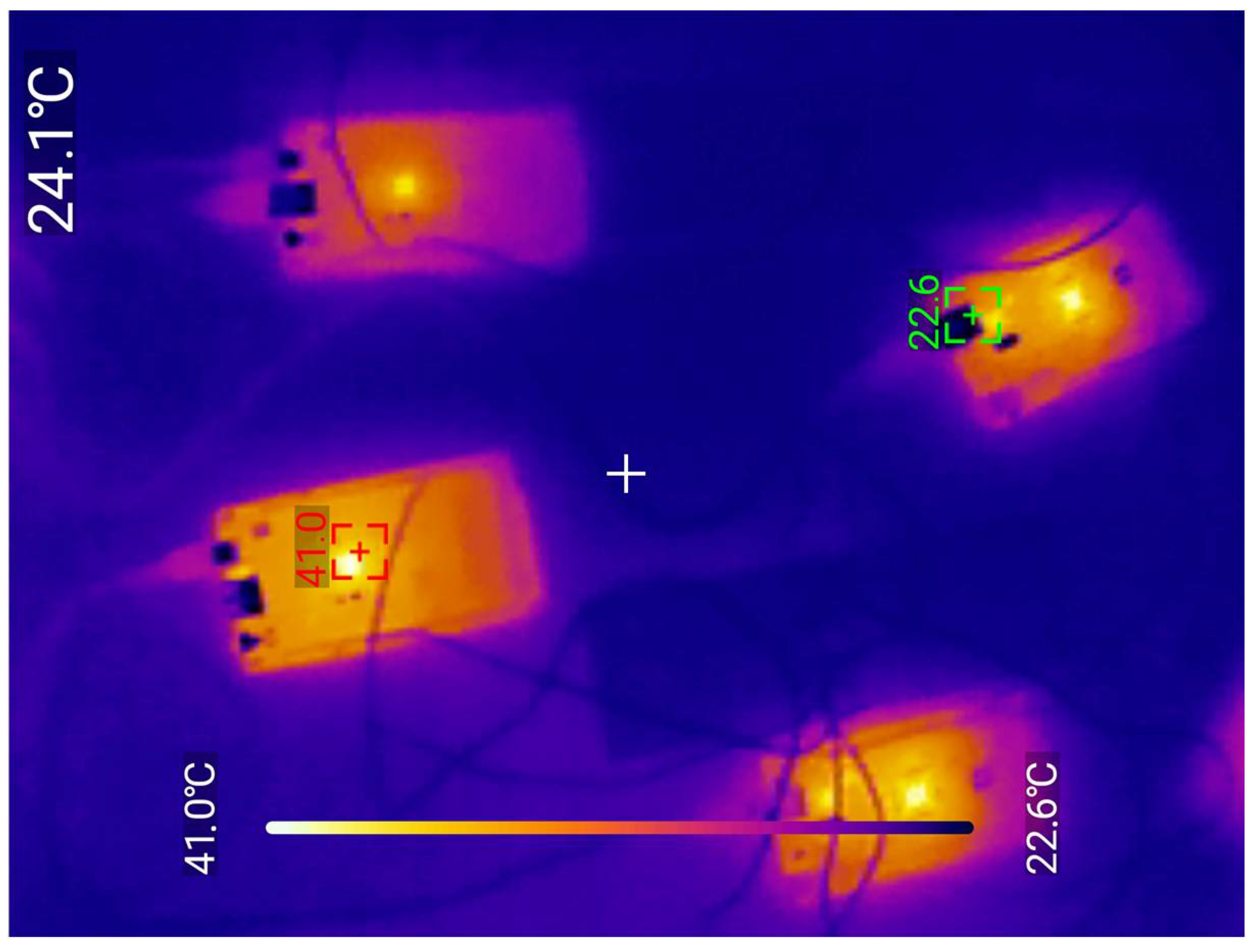
The two Arduino MEGA 2560 R3s on the right are responsible for ECC encryption and ECC decryption. It is more than obvious that many keystrokes “push” the Arduinos to constantly operate, to be stressed and as result heat the modules. However, the upper left Arduino GIGA R1, which sends only the keystroke signals to the laptop, is less stressed. It is worth noting that modified ECC requires more encryption and decryption time than the AES. In Figure 5, a thermal imaging photo can be seen, depicting the heat on the two Arduino GIGA R1 and the two Arduino MEGA 2560 R3, when modified ECC is used for the encryption and decryption of the keystrokes. The two Arduino MEGA 2560 R3 on the right side of Figure 5 seem to be more stressed due to the extensive operation of modified ECC encryption and decryption.

4.3. XOR-Encrypted Wired Keyboard

The current github library was used for the current encryption [16]. Once again, the experiments follow the same rationale as before, meaning one Arduino GIGA R1 (2) which captures the keystrokes through the USB keyboard (1). An Arduino MEGA 2560 R3 (4) is connected via a voltage translator (3) (in order to translate 3.3 Volt signals to 5 Volt signals and the opposite) to the Arduino GIGA R1 (2). Serial3 is used from both Arduinos (4) and (5). The Arduino MEGA 2560 R3 (4) realizes the XOR encryption of the gathered keystrokes and transmits it to the other Arduino MEGA 2560 R3 (5) via the UART (Universal Asynchronous Receiver–Transmitter) protocol (Serial3) and a simple wire connection. The end Arduino MEGA 2560 R3 (5) gathers the keystrokes and decrypts using the XOR method. It then sends them to Arduino GIGA R1 (7) which propagates them as suitable keystrokes to the end PC/laptop/cloud/terminal (9). The voltage translator (6) is needed for the communication of the parts (5) and (7) as explained above. The communication between the Arduino GIGA R1 and Arduino MEGA 2560 R3 takes place via Serial3. The keystrokes are transformed from ASCII to HEX before being transmitted from the Arduino MEGA 2560 to the other Arduino MEGA 2560 R3. The receiver Arduino MEGA 2560 R3 transforms the received encrypted packet from HEX to ASCII and then all data are decrypted. This is the way that such a simple XOR encryption/decryption library operates. The aforementioned modules are supplied by a USB Hub (8), which can provide them with adequate current, without causing any problems to the laptop USB ports. Figure 6 below depicts the abovementioned process with numbered parts.

4.4. Spritz-Encrypted Wired Keyboard

For the current encryption, the following github library was used [17]. The idea here is the same as in AES, ECC, and XOR ciphers’ circuits construction. Two Arduino GIGA R1s to receive and handle the keystrokes, two Arduino MEGA 2560 R3s for encryption and decryption, and two level translators for appropriate level communication between the 3.3 Volt and the 5 Volt modules are used, and vice-versa. The encryption/decryption keys are obviously the same, since the implementation is based on symmetric key cryptography. The experiment is based on what is depicted in Figure 6, with the only difference being the algorithmic protocol.

5. AES-Encrypted Wireless Keyboard Using Zigbee Modules

Zigbee is designed by Zigbee alliance, which includes many companies, such as Ember, Freescale, Chipcon, and others, ranging from semiconductor and software companies to original equipment producers. Zigbee and IEEE 802.15.4 differ, since Zigbee stands for a standard-based network protocol, which is supported by Zigbee alliance for transportation services of the IEEE 802.15.4. In other words, Zigbee alliance is responsible for the Zigbee standard and IEEE for the IEEE 802.15.4. Similarly, Zigbee alliance is responsible for the network definition, while IEEE 802.15.4 for the LR-WAN [25].
Zigbee works in what is called ISM (Industrial Scientific Medical) radio channels. It uses the 2.4 GHz band. However, modules for commercial utility-measuring and medical device data collection usually make use of sub-GHz channels. For instance, a Zigbee operating in North America, Australia, and Israel operates at 902–928 MHz. In Europe, the Zigbee modules work in a range between 868 and 870 MHz, and in China, the range is 779–787 MHz. As far as the aforementioned countries are concerned, they still operate in the 2.4 GHz band for the most globally purchased Zigbee modules meant for home use. Zigbee data rates work around 20,000 bits/s for the sub-GHz bands to about 250,000 bits/s for channels existing on the 2.4 GHz band [26].
A Zigbee module consumes a very small amount of energy. In most cases, it uses 1 mW [27], 2 mW [28], or even 63 mW [29], which are solutions provided by the DIGI manufacturer. For the experiments of the research presented in this paper, the Xbee Zigbee 2 mW RP-SMA antenna display the following features [28]:
  • 3.3 V @ 40 mA.
  • 250 kbps Max data rate.
  • 2 mW output (+3 dBm).
  • 400 ft (120 m) range.
  • Built-in antenna.
  • Fully FCC-certified.
  • Six 10 bit ADC input pins.
  • Eight digital IO pins.
  • 128 bit encryption.
  • Local or over-air configuration.
  • AT or API command set.
There are three models of Zigbee (Xbee) that can operate via the Xbee X-CTU platform. These are the following [30]:
(a)
Point-to-Point.
(b)
Star.
(c)
Mesh.
Figure 7 depicts what a typical Mesh and Star network look like [25].
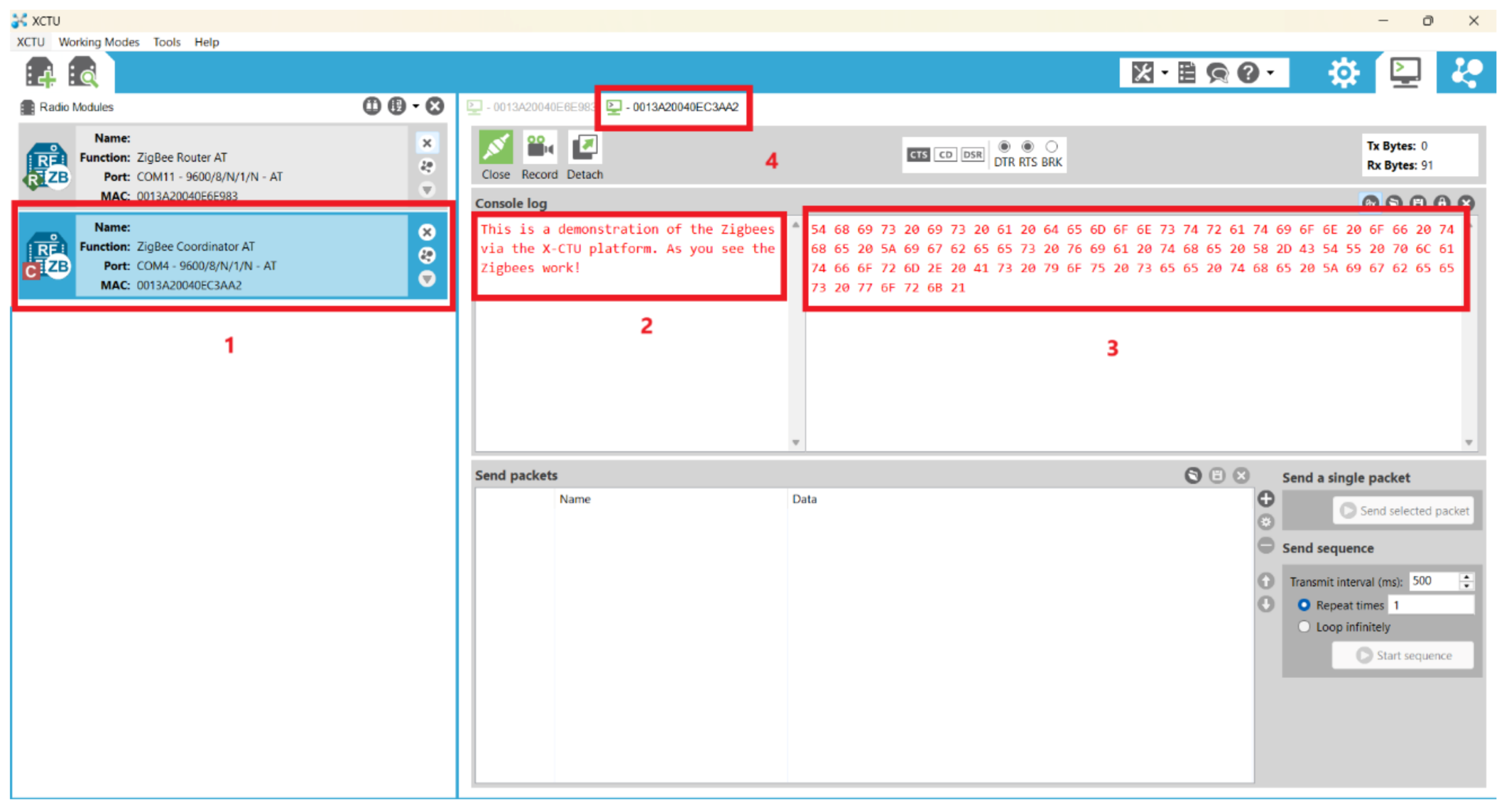
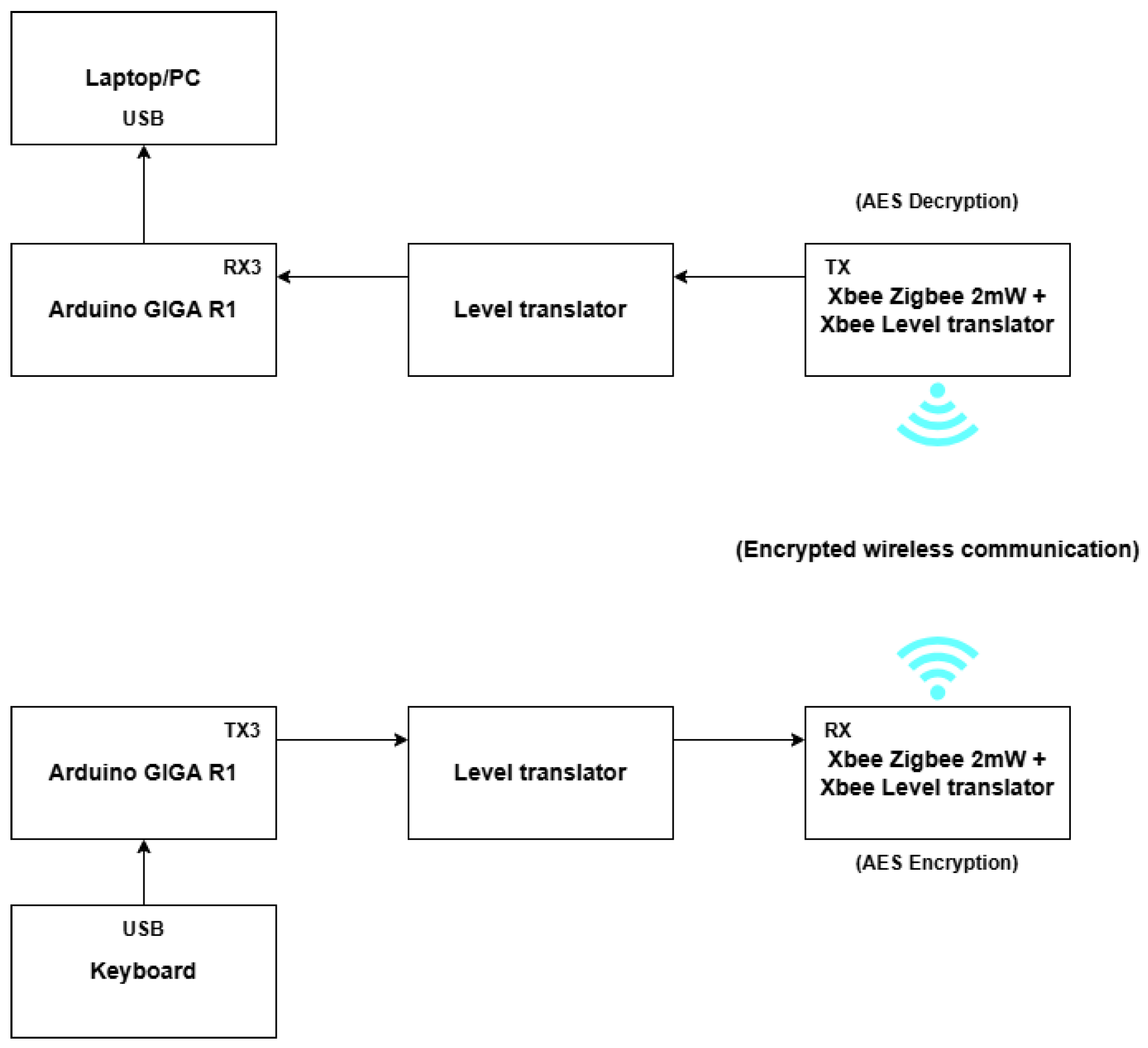
The fact that Xbee Zigbee contains 128 bit AES encryption offers the choice to enable the specific flag of the Xbee module via X-CTU platform. Thus, there is no need to use the AES encryption/decryption Arduino library that was used in the wired keyboard solution in Section 4.1. The solution used in the current approach was a point-to-point one, since the connection takes place between the USB Keyboard where the input is fed, and the Arduino end device which is connected to the laptop. There are four sections highlighted in each Figure (Figure 8 and Figure 9): the transmitting Zigbee module is numbered with (1), and the text sent by the current keyboard (blue color letters denote the sending text and red color letters denote the received text) is depicted with (2). The equivalent hexadecimal text of the pressed characters is highlighted with (3) and (4) and denotes the current operating module.
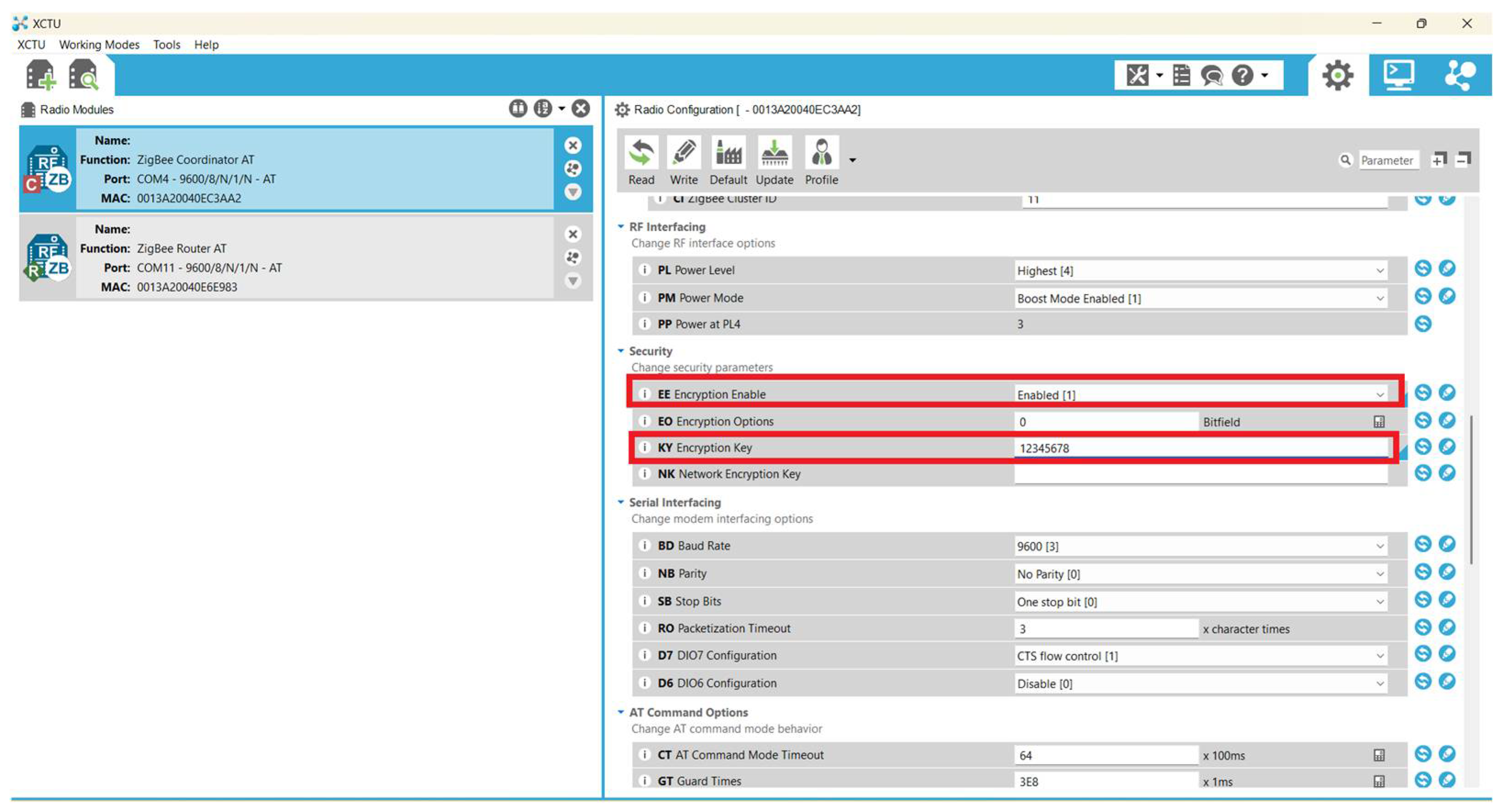
Figure 10 shows the configurations made regarding the AES encryption. Two flags are important in order to encrypt the communication between the Zigbee modules. The first one is the EE (Encryption Enable) flag, which must be set to “Enable [1]”, and the KY (Encryption Key) where the user should enter the encryption key.
Figure 11 depicts the whole construction with the Zigbee modules. The user uses the USB keyboard (1) to send the keystrokes. The (1) is connected directly to the USB slot of Arduino GIGA R1 (2) which gathers the key presses and sends them via its UART (TX3 pin) to the Zigbee module (4) using the level translator (3). It should be noted at this point that although Xbee Zigbee operates at 3.3 Volts power supply and logic, the spaces between their pins are incompatible with the breadboard’s spaces, accounting for the attachment on Xbee adapters as well as for translating 3.3 Volts to 5 Volts and vice versa. However, Arduino GIGA R1 operates at 3.3 Volts, proving there is a need for another level translator (3), in order to make the Arduino GIGA R1 (2) and the Xbee Zigbee adapter + Xbee level translator (4) communicate. The Zigbee (4) sends the data wirelessly to the other Zigbee (5), which uses a slightly different Xbee voltage translator that outputs the data to a USB interface, capable of connecting it to the end PC/laptop (6).
In Figure 12, there is a demonstration of the characters sent by the USB keyboard to the end PC/laptop, through the construction is depicted in Figure 11 and has been previously analyzed. The characters as well as the hexadecimal depiction can be seen on the console log of the X-CTU software—version: 6.5.13 (Figure 12).
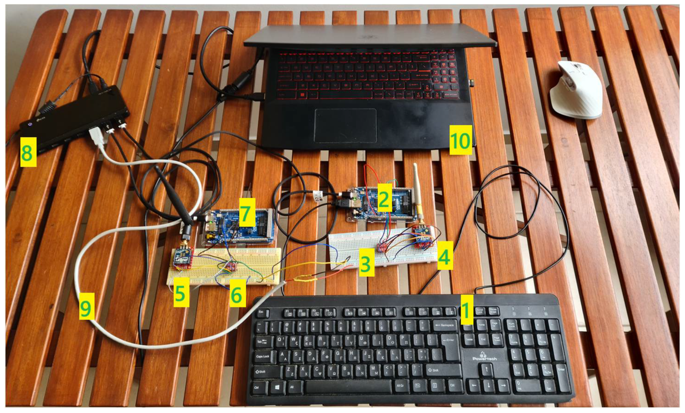
Figure 13 presents the 2nd experiment with an Arduino GIGA R1 connected to each Xbee Zigbee via a level translator. This is the actual communication set up using two Xbee Zigbees (4, 5) which communicate with the two Arduino GIGA R1s (2, 7) via the two level translators (3, 6). All the components, including the extra power supply (9), are supplied by the USB hub (8), which can provide enough current for all the connected modules. The user presses the keys in the USB keyboard (1) and the end keystrokes are depicted at the end laptop/cloud/terminal (10). The reason for implementing the experiment in Figure 11 was to demonstrate the actual inner configuration of the Xbee Zigbee modules including the AES key encryption arrangements. However, the experiment in Figure 13 presents the actual construction which can be used to establish a secure communication between the USB keyboard and the end device (laptop/desktop/cloud/terminal). Both experiments send keystrokes pressed; however, the aforementioned experiment operates only on X-CTU terminal, whereas the second experiment operates as an actual USB keyboard sending secure keystrokes in any Windows/Linux/MacOS application as the normal USB keyboard.
Figure 14 shows the block diagram of the Zigbee modules, the Arduino GIGA R1, and the rest modules for making this approach work., just to underline at this point that there is no usage of Arduino GIGA R1 at the receiver part, connected to the laptop in the experimental constructure (Figure 11).
In Figure 14, there is a presentation of an ideal block diagram with the usage of Arduino GIGA R1 connected in the receiver’s (laptop) side.
At this point, it should be underlined that the distance between the USB keyboard (transmitter) and the end PC/laptop/cloud/terminal (receiver) would be around 2–3 m, so as to eliminate any doubt about attenuation, although the Xbee Zigbees require minimal energy to operate and only an output of 2 mWatt output. They can also cover distances up to 40 m indoors and distances up to 120 m outdoors [31].

6. Encrypted Infrared Connection at 940 nm

In [32], the researchers investigate a multiband mid-IR Free-Space Optical (FSO) communication system using channel multiplexing rationale to rise the data capacity of the mechanism. Various channel multiplexing techniques are delegated as well as channel degradation schemes for mid-IR beam spread via the atmosphere. Moreover, they analyze different approaches for mid-IR data modules for receiving and transmitting information in the mid-IR FSO channels. As a final approach, many modern multi-channel mid-IR FSO communication analysis with the result of increased final data rates are discussed.
In another research [33], the authors propose a narrow-bandgap NFA which stands for: non-fullerene acceptor, with a response time of around 91 ns at 880 nm, made of organic materials and called OPD (organic photodetector). It can be used for high data communication with a rate of about 80 MHz, maintaining a bit error rate at 3.5 * 10−4, making it a suitable product for next-generation fast and flexible modules in the field of optical communications.
In [34], the authors analyze the security of mid-IR FSO communications systems. More specifically, they analyze the physical-layer security from a theoretical perspective, by paying attention to the atmospheric turbulence, atmospheric attenuation, as well as divergence attenuation. They also analyze the results of atmospheric turbulence, the distance of the realized link, the visibility on secrecy capacity, and the possibility of interrupt. They compare NIR (near-infrared) and MIR (mid infrared) schemes in the rationale of secrecy capacity and interrupt possibility. From a theoretical point of view, it is supported that the secrecy capacity of NIR systems is smaller than the equivalent of MIR systems. As they claim, MIR systems show better performance than NIR systems.
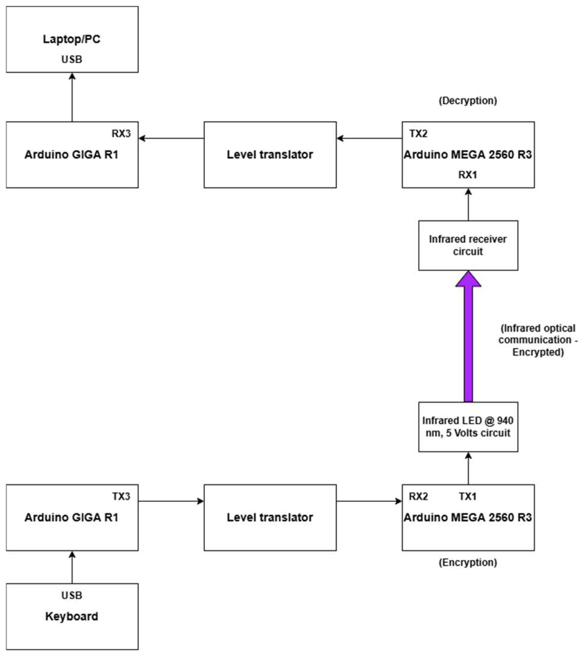
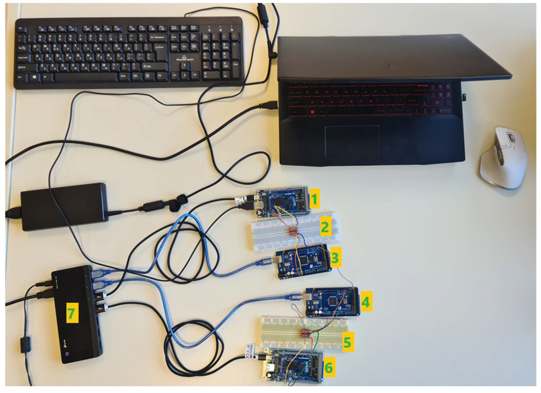
Once again, the idea is the same as with the fiber optic circuit. The difference in relation to the fiber optic circuit is encryption and decryption, because IR light sent from the transmitter is spread/scattered all over the space, making it vulnerable to an eavesdropper. For this reason, the user presses the keys in the USB keyboard (1) connected to the Arduino GIGA R1 (2). The latter sends the messages for encryption to Arduino MEGA 2560 R3 (4) via the bidirectional level translator (3). The (4) is connected to the IR emitter (8) with a small resistor to match the 5 V voltage and also limit the current. The electrical signal is then transformed to optical signal, which is received by the IR receiver circuit (9) connected to the Arduino MEGA 2560 R3 (5). The (5) decrypts the message and transmits it to Arduino GIGA R1 (7) via the level translator (6), and the (7) sends the message to the end device (PC/laptop) (12). All the Arduinos are supplied by the USB hub (11) and for the IR emitter and IR receiver, an external power supply is provided (10).
As it is depicted in the block diagram in Figure 15, there are the usual voltage translators for the communication between the Arduino GIGA R1 and the Arduino MEGA 2560 R3. Once again, there is one-way communication (Figure 16), since the USB keyboard only sends keystrokes. There is no need for feedback, explaining why only one RX or TX pin is used every time. Figure 17 shows the electrical “imprint” of an encrypted message sent by the IR emitter.

7. Unencrypted USB Keyboard Communication

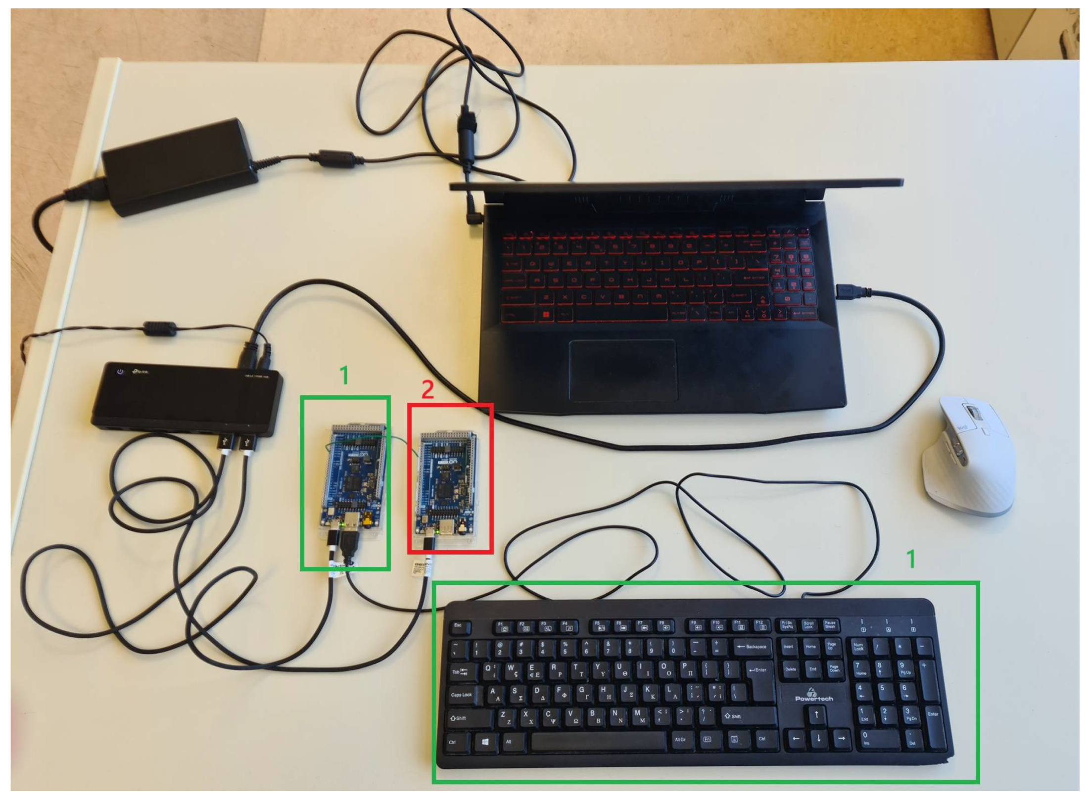
In order to have an estimation of how well or not the aforementioned mechanisms for securing USB keyboards work, experiments on unencrypted keystrokes were conducted. The idea was to measure the keystrokes from the moment they were performed until presented at the end PC/laptop/terminal/cloud. There was no need of Arduino MEGA 2560 R3 for this implementation, since there was no encryption/decryption, and neither were any level translators used. There was only two Arduino GIGA R1s connected in between via the Serial4 port. The one Arduino GIGA R1 was connected to the USB keyboard (1), whereas the other Arduino GIGA R1 (2) to the end PC/laptop/terminal/cloud. The C/C++ code programmed/built in Arduino IDE (version 2.3.6) and then uploaded to the Arduino modules, “catches” the time the keystroke starts and the time the letter is presented on screen. All the described components are depicted in Figure 18. The keystrokes need 0.8 s on average during the experiments to “travel” from the USB keyboard to the end PC/laptop/terminal/cloud’s screen.

8. Key Points for Making the Circuits Work Correctly Without Problems and (Possible) Attacks

8.1. UART Problems

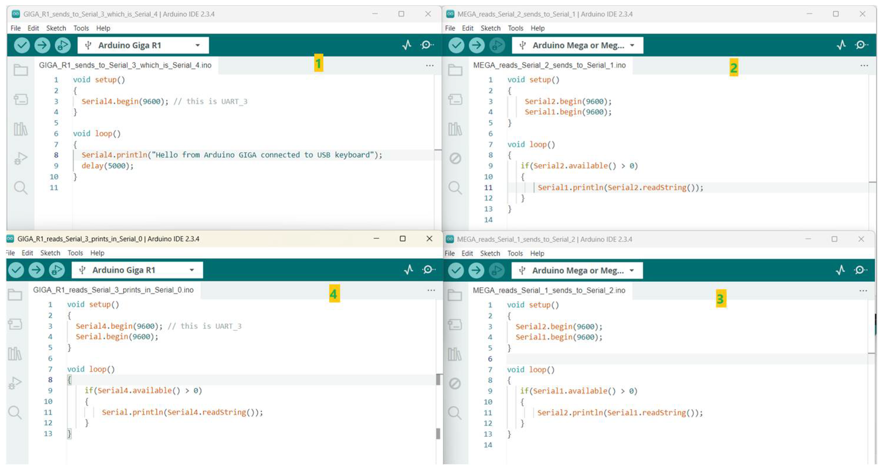
Before starting the experiments, the following test took place. It is very crucial to notice that Arduino MEGA 2560 R3 contains four UARTs [35] where each one corresponds to the related UART in C/C++ language code. For instance, UART0 is related to the Serial C/C++ command, UART1 is related to the Serial1 command, UART2 is related to the Serial2 command, and UART3 is related to the Serial3 command. The previously described sequence does not occur with the Arduino GIGA R1 WIFI. In Arduino GIGA R1, the following matching takes place [36], as depicted in Figure 19:
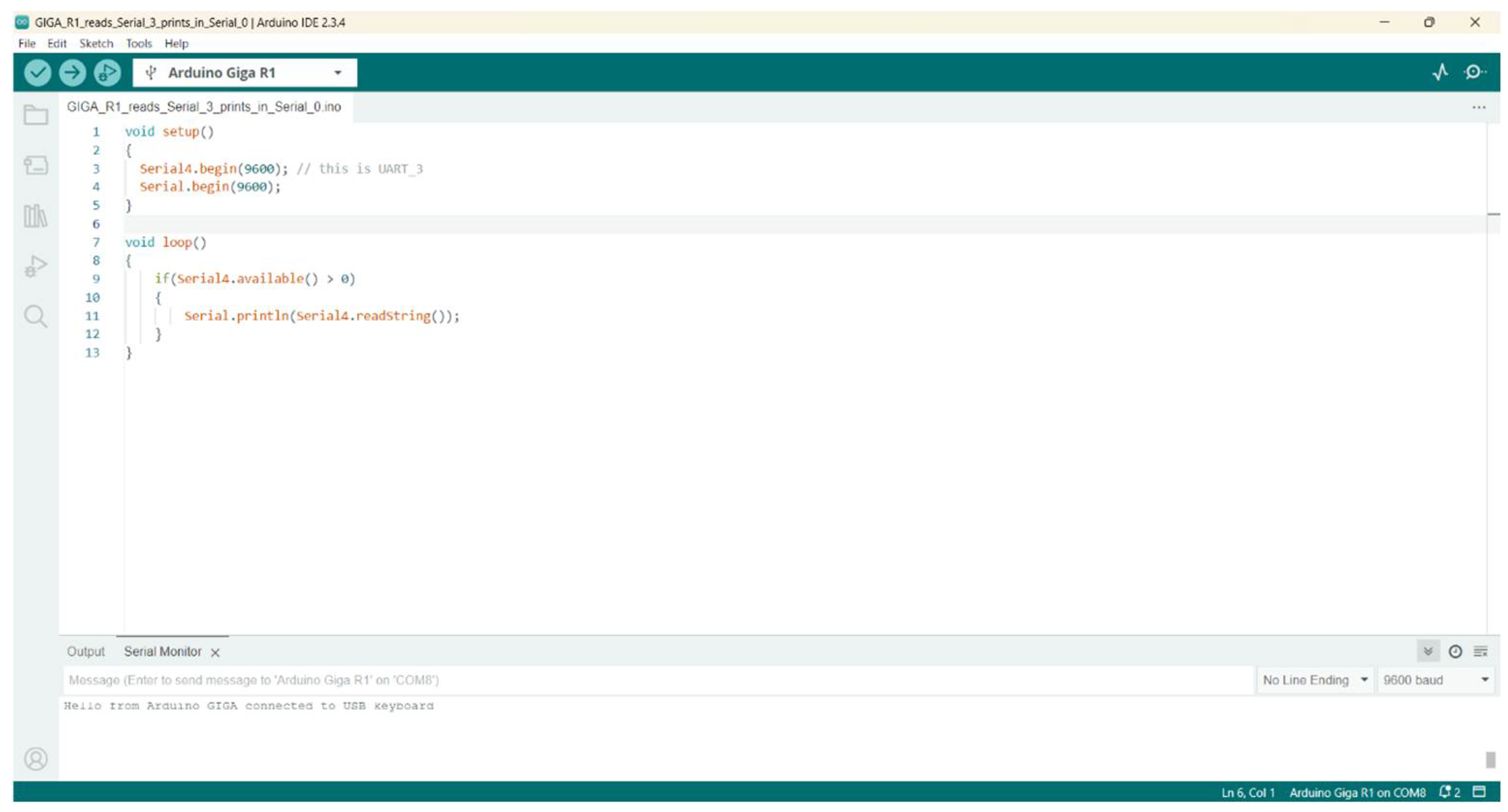
The above sequence means that in order to initialize UART3 in Arduino GIGA R1, we need to use Serial4.begin(9600); command and not Serial3.begin(9600); as this would be the case for Arduino MEGA 2560 R3. The various C/C++ codes for testing the circuit depicted in Figure 20 can be seen in Figure 21. In (1) of Figure 20, the Arduino GIGA R1 (place 1, Figure 21) sends a message to Arduino MEGA 2560 R3 (place 3, Figure 20) via the C/C++ code (place 2, Figure 21). Arduino MEGA 2560 R3 (place 4, Figure 20) receives the message via the use of the C/C++ code (place 3, Figure 21) and sends it to Arduino GIGA R1 (place 6, Figure 20) which sends the received message to the Arduino IDE platform of the end PC/laptop via the code (place 4, Figure 21). Figure 22 shows the received test message to Arduino GIGA R1 connected to the end PC/laptop via the USB hub.
The aim was to test the UART of the Arduino GIGA R1 (1, 6), Arduino MEGA 2560 R3 (3, 4), and the bidirectional level translators (2, 5) depicted in Figure 20.

8.2. “Garbage” When IR Emitter and IR Receiver Are Not Aligned

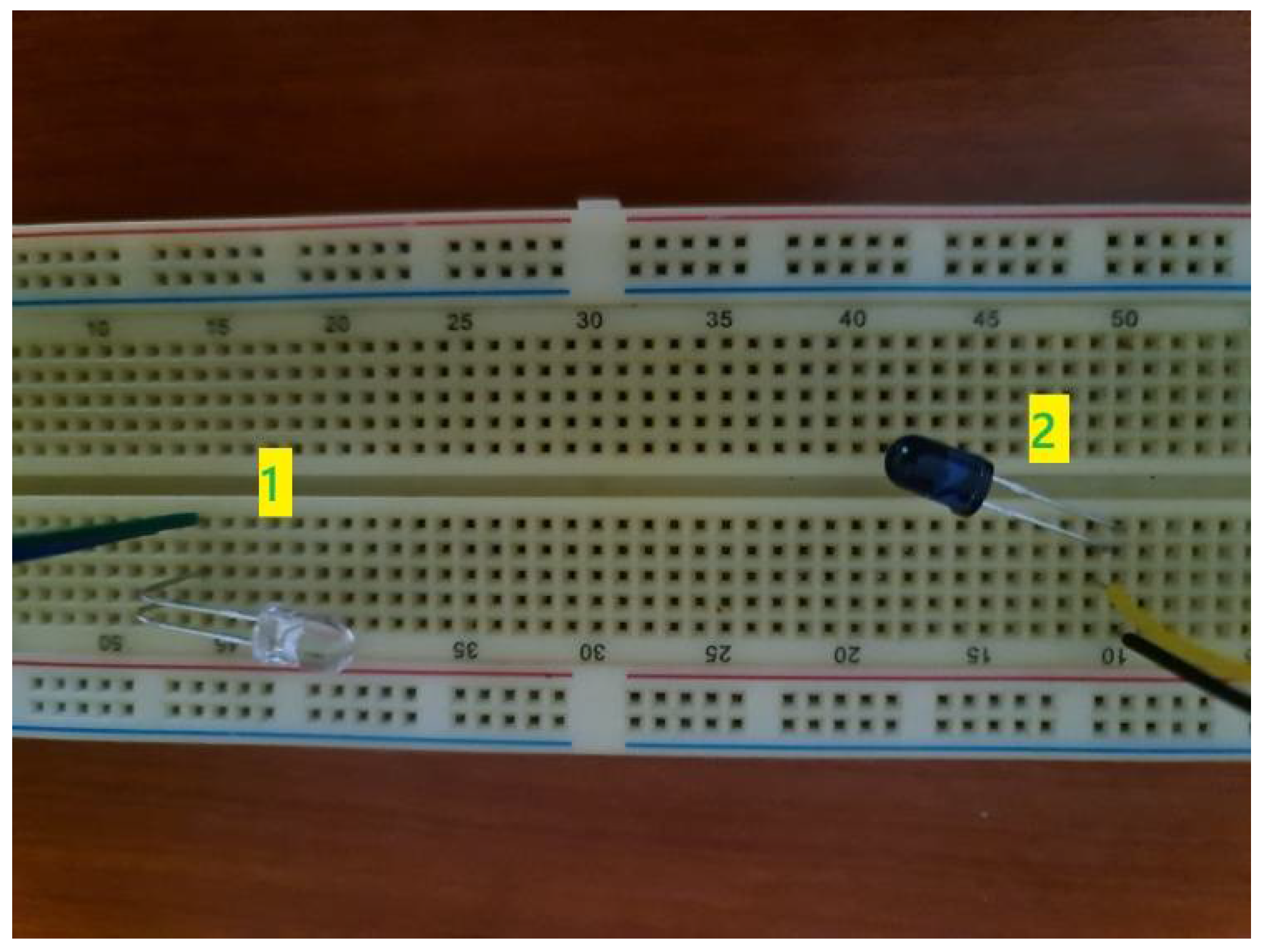
Another issue was the fact that if the IR receiver (2) and the IR emitter (1) were not in the same “line” (Figure 23), the received messages from the USB keyboard faced problems, containing “garbage” as shown in Figure 24. Of course, the IR emitter and IR transmitter are too close when conducting the experiments. However, in real situations, the space in between could be more than 2 m, so such problems would not exist, since LEDs have an initial viewing angle of around 30 degrees which can expand, allowing operation without problems, because some space is left around the IR LED and IR receiver.

8.3. Interference of Infrared Communication with Ambient Light

As it is known, Infrared communication that was presented before, uses an IR LED and an IR receiver both operating in the IR spectrum of 940 nm. Throughout the extensive experiments, the authors of the current research paper, luckily, did not observe any problems, probably because the experiments were conducted indoors with tinted windows. There are numerous works in the literature that analyze the effect of ambient light in IR communications.
In [37], the researchers present the results of many experiments and extensive measurements using artificial light, which causes serious in-band perturbations for systems using bitrates in the range up to Mbps. As stated, fluorescent light sources based in solid state ballasts can cause interfering noise in the wider band. They also support that the latter is the most serious cause of degradation in wireless systems based on optical receivers and transmitters.
Research in [38] states that IR communication is based on light waves, which are affected by interferences from light emitted by light sources. The latter can cause problems in the IR data transmitted from transmitters to receivers. Moreover, wrongly received data or loss might result as well.
In [39], a table is quoted, where the interference factor in IR communication is caused by ambient light.
In order to present a general view of the optical spectrum and possible interference with the IR communication experiment, the following module was used, “AS7341 Spectral Color Sensor”, connected to an Arduino MEGA 2560 R3 via the I2C port. The characteristics of the module are the following [40]:
  • It incorporates an AS7341 chip, which integrates eight visible spectrum channels, one near-infrared channel, and one no filter channel.
  • Contains six independent 16 bit ADC, which enables processing of data in parallel.
  • Specified channel to identify ambient light flicker on the specific frequency.
  • two high brightness LEDs, that can be used as fill light in a dim environment.
  • Interrupt pin to output inner ADC real-time operating status.
  • Features spectrum interrupt detection, with programable high/low thresholds.
  • Provides GPIO (General Purpose Input/Output) pin.
  • Voltage translator, compatible with 3.3 V/5 V operating voltage.
The current chip provides values of the light intensity of the different wavelengths, existent during the Infrared communication USB keyboard experiments. Figure 25 shows the various raw values gathered by the AS7341 chip. Each channel contains a range and it obviously corresponds to a different color.
The spectral response of the AS7341 chip is fixed by individual channels, operating in the range: 350 nm to 1000 nm, from which eight channels are centered in the VIS (visible spectrum), while there is another one channel in the NIR (near-infrared), and one clear channel, as claimed in the following datasheet [41]. It is written in the same datasheet that the NIR channel along with other VIS channels may give information of the environmental ambient light, including light source identification.

8.4. Comparison of Evaluated Approaches

Table 1 includes all the proposed solutions with the related communication type used, the type of encryption (if used), the encryption scheme used, and the difficulty level concerning software and hardware configurations. Number “1” stands for low difficulty, number “2” indicates medium difficulty.
As Table 1 shows, encryption is required in wired and wireless solutions to secure propagating data in order for the propagating data to be secure. This occurs also in the cases of free-space Infrared communication (IR), since the light does not target the same way a laser, for example, does, making it vulnerable to an eavesdropper carrying just an IR receiver. According to the table, the 5th column depicts the difficulty of the configuration, including software and hardware. As it is obvious, when encryption is used, the C/C++ configuration is more complex since the Arduino GIGA R1 must send the data to Arduino MEGA 2560 R3 to be encrypted before being transmitted. Then, Arduino MEGA should decrypt the data and send them to the Arduino GIGA R1, which reformats and sends the keystrokes to the end device. The last column includes information about each experiment without calculating the cost of the laptop and the mouse.
Reviewing the findings captured in Table 1, it can be easily observed that the cost of using the wireless solution, meaning one Zigbee and Arduino GIGA, is lower than the solution concerning the fiber optic one. The latter uses two Arduino GIGA R1s modules which might cost about 90 euros each, a fiber optic cable, and two Gravity UART Fiber Optic Transceiver Modules, which increase the experimental cost, whereas the solution of the one Zigbee and one Arduino GIGA R1 seem to be less expensive.
There have been experiments of the ECC, AES, XOR, and Spritz regarding the encryption and decryption times via the use of Arduino MEGA 2560 R3. In one of the test cases, the Arduino ran the ECC/AES/XOR/Spritz algorithm many times and an average value was kept, as depicted in Table 2. It is easily understood that Spritz encryption/decryption protocol is faster than AES/ECC/XOR. AES/XOR/Spritz fall under the general “umbrella” of symmetric cryptography, whereas ECC belongs in the area of asymmetric cryptography. They are two different approaches accounting for different performances as it can be inferred by the encryption/decryption times (given in milliseconds).
It should also be noted that the following parameters were used from the ECC library, which is presented in Figure 26.
As far as energy consumption is concerned, the following values were measured in the lab:
  • Connecting the two Arduino MEGA 2560 R3s and the two Arduino GIGA R1s in the supply hub, without having connected any other module or wires, the current draw is around 363 mA, at 5 Volts, so there seems to be a power consumption of about 1815 mWatts.
  • Implementation with AES encryption communication with the two Arduino MEGA 2560 R3s and the two Arduino GIGA R1s, with the two level translators, and the related wires connected, the meter showed 394 mA current draw, at 5 Volt, with a 1970 mWatts power consumption.
  • Implementing the ECC encryption scheme, with the two Arduino GIGA R1s, the two Arduino MEGA 2560 R3s, the two level translators, and the related wires connected, the power meter displayed 403 mA current draw at 5 Volts, so there seems to be a power consumption of 2015 mWatts.
  • Construction of the fiber optic communication, without using the two Arduino MEGA 2560 R3s or the level translators, but including the two fiber optic transceivers and the fiber optic cable, indicates reduced power consumption of about 1770 mWatts, with current draw 354 mA at 5 Volts, which is reasonable, since not all modules were used.
  • The realization using XOR and Spritz ciphers followed the same circuit construction as the AES and the ECC. XOR encryption/decryption scheme shows a power consumption of 2030 mW, with a current draw around 406 mA, which is similar to the ECC-based experiments. The surprise is that Spritz-based scheme needs 423 mA, guiding to 2115 mW power consumption, which makes it the most energy harvesting experiment of all the implementations regarding secure keyboard communication.
  • Regarding IR LED-encrypted communication, using the two Arduino MEGA 2560 R3s, the two Arduino GIGA R1s, the two level translators, extra resistors, an IR LED, and an IR receiver, indicates a power consumption of 2030 mWatts at 5 Volts, with 406 mA current draw.
  • Zigbee communication between the two Arduino GIGA R1, the level translators, and the Xbee Zigbee with their adapter, but without using Arduino MEGA 2560 R3, needs around 330 mA current at 5 Volts, so there seems to be a power consumption of about 1650 mWatts.
All the aforementioned power consumption values are summed and depicted in Figure 27, where the reader can observe a comparison of the different experiments.
Table 3 shows the delay (in seconds) for each keyboard scheme, meaning the timestamp that a key is pressed in the USB keyboard and the timestamp when received in the end device (laptop/desktop/cloud/terminal). As it is clear from the table, when AES/XOR/Spritz encryption/decryption or ECC encryption/decryption scheme is used, the delay seems to be higher (and stable), meaning around 4, 4, 3, and 6 s, respectively. When no encryption/decryption scheme is used, as it occurs in fiber optic realization, the delay is about 1 s. Surprisingly, the delay seems to be rather small in the Zigbee encryption scheme, where no Arduino MEGA 2560 R3s are used, and the AES algorithm is realized inside the Xbee Zigbee chip, contrary to the rest of encryption schemes, which is around 1 s.
At this point, it should be noted that encrypted communication can also be realized using the built-in Arduino GIGA R1 Wi-Fi or BLE modules.
The fact that the delays are that long, in Table 3, is related to encryption and decryption processes taking place in reduced capabilities of 8 bit, 16 MHz processors [42] contained in Arduino MEGA 2560 R3. The experiments regarding AES/XOR/Spritz and ECC encryption as well as AES with InfraRed communication use four Arduino modules in total together with long wires. These kind of circuits insert delays that are captured in Table 3. The experiment with the fiber optic cable uses only two Arduino GIGA R1s, which are much faster than Arduino MEGA 2560 R3. Arduino GIGA R1 incorporate dual core 32 bit CPUs (a Cortex®-M7 at 480 MHz and a Cortex®-M4 at 240 MHz) (ARM manufacturer, Cambridge, UK) [43] which is much stronger than Arduino MEGA 2560 R3 processor, as analyzed above. In the fiber optic experiment, there is no encryption or decryption, which significantly reduces the time duration between the keystrokes in the USB keyboard and their appearance in the end PC/terminal/Cloud/laptop. As far as the time delay of 1 s in Xbee Zigbee experiments is concerned, although AES encryption/decryption occurs, it is clear that the process takes place in a hardware chip (possibly a chip exclusively designed for encryption/decryption purposes) in the Xbee Zigbee modules, and proves that Xbee Zigbee uses low-power CPUs with constraints. Furthermore, only one (max two) Arduino GIGA R1s are used in the experiments, without the delay load of Arduino MEGA 2560 R3 and the heavy encryption/decryption processing in their modules, as it was true in the other experiments. This is the reason why the Xbee Zigbee experiment demonstrates low delays of around 1 sec. Encryption/decryption with modified ECC demonstrates the longest delays. The truth is that ECC is asymmetric cryptography contrary to AES’s not symmetric one. Asymmetric cryptography is much “heavier” when it comes to processing, and it is used only in unsafe environments in order for the two parts to exchange their initial keys and continue communication with AES encryption, which is much “lighter” and invented for real-time secure communication. Regarding XOR and Spritz ciphers, they demonstrate 4 and 3 s delays, respectively, showing values similar or lower than the AES cipher, and lower than ECC. Once again, it is proven that symmetric cryptographic algorithms show lower delays than the ECC-based algorithm.

8.5. Testing the Fiber Optic Cable with Spectrum Analyzer

In the current research work, there is the claim that fiber optic cables are immune to EMI/RFI, guaranteeing safety. Moreover, without end-to-end encryption, the signals inside the fiber optic cable cannot be eavesdropped. In order to provide evidence for this claim, a spectrum analyzer (model: RIGOL DSA 815-TG) was used, capable of analyzing wireless signals in the range 9 kHZ–1.5 GHz. Near-field EMC probes (Tekbox TBPS01 EMC near-field probes) were used in the experiments, both electrical (E5) and magnetic (H20). The electric and magnetic near-field EMC probes were placed over the fiber optic cable, as presented in Figure 28. The results show neither electric nor magnetic effect. In order to test whether the EMC probes were operating correctly, they were placed in the USB keyboard cable (just for a testing reason and not to extract pressed keystrokes), where the result in the spectrum analyzer shows a signal of around −45 dBm (around 32 nWatts) in the range 85 MHz–110 MHz. Of course, the signal is very low, since there is no amplification, but it indicates the following: the electrical cables show the appearance of EM field, whereas the fiber optic cables do not, which is expected, as presented in the literature in previous paragraphs. Figure 28 shows the frequency spectrum in the range 75 MHz–125 MHz, when placing the electric EMC probe over the fiber optic cable (Figure 28), as it is obvious there is no electrical field caused by the fiber optic cable.
Figure 28 shows the result of the spectrum analyzer in the range of 75 MHz to 125 MHz, where a signal is gathered when the electrical EMC probe is placed on the keyboard’s USB cable. The same figure also depicts the magnetic EMC probe placed on the fiber optic cable and the result in the spectrum analyzer, where no signal is gathered. Similarly, the magnetic EMC probe is placed over the keyboard’s USB cable, where an electrical signal is gathered, showing also a magnetic field around the electrical cable as depicted in the spectrum analyzer.

8.6. Attacking the AES- and ECC-Encrypted Keystrokes

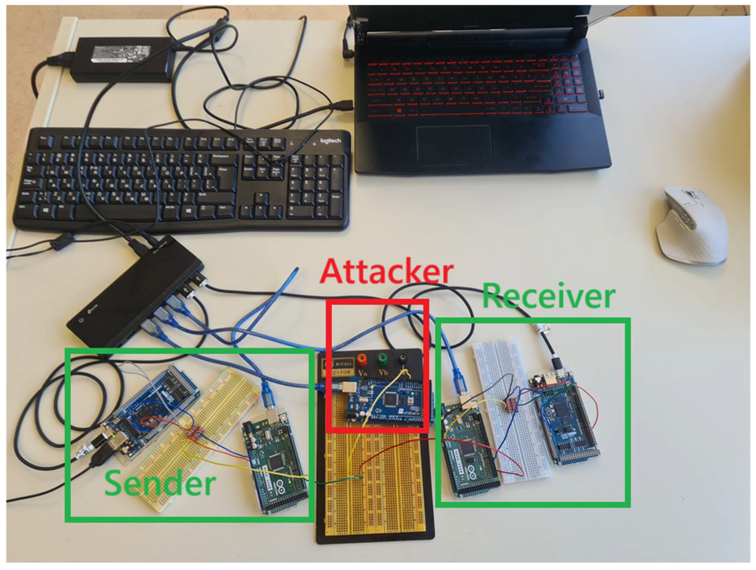
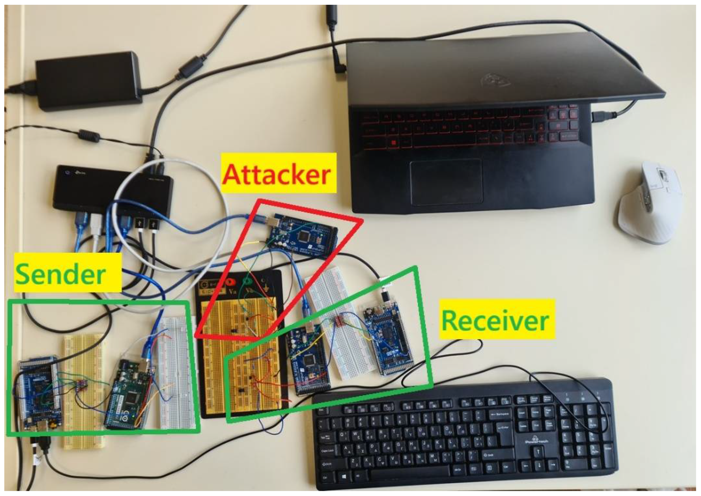
In order to introduce the attacker, the construction of AES/ECC was built. The same experiment can work with XOR/Spritz ciphers. It consists of the Arduino GIGA R1 and the Arduino MEGA 2560 R3, as it was presented in detail in the previous section. This time, the new part is a 3rd Arduino MEGA 2560 R3 (“attacker”), which is connected to the cable connecting the Sender and the Receiver. The cable transfers encrypted keystrokes from the Sender to the Receiver part. The attacker tries to eavesdrop the data transmitted (Figure 29).
The 1st experiment consists of AES encryption/decryption and the data that the attacker gathers are presented in Figure 30. The keystrokes sent by the receiver are in place “1”. The data gathered by the attacker are in place “2”. Obviously, the attacker cannot identify what data are transferred, since they are encrypted with AES symmetric key, and the encryption/decryption key is unknown to the eavesdropper.
The 2nd experiment is based on the same structure as depicted in Figure 30, but this time, ECC is used. Figure 31 shows the place “1” where the keystrokes are presented, and the place “2” where the encrypted data are gathered by the attacker. The attacker cannot identify which keystrokes are transmitted, because they are encrypted.

8.7. An Attack on the IR Communication

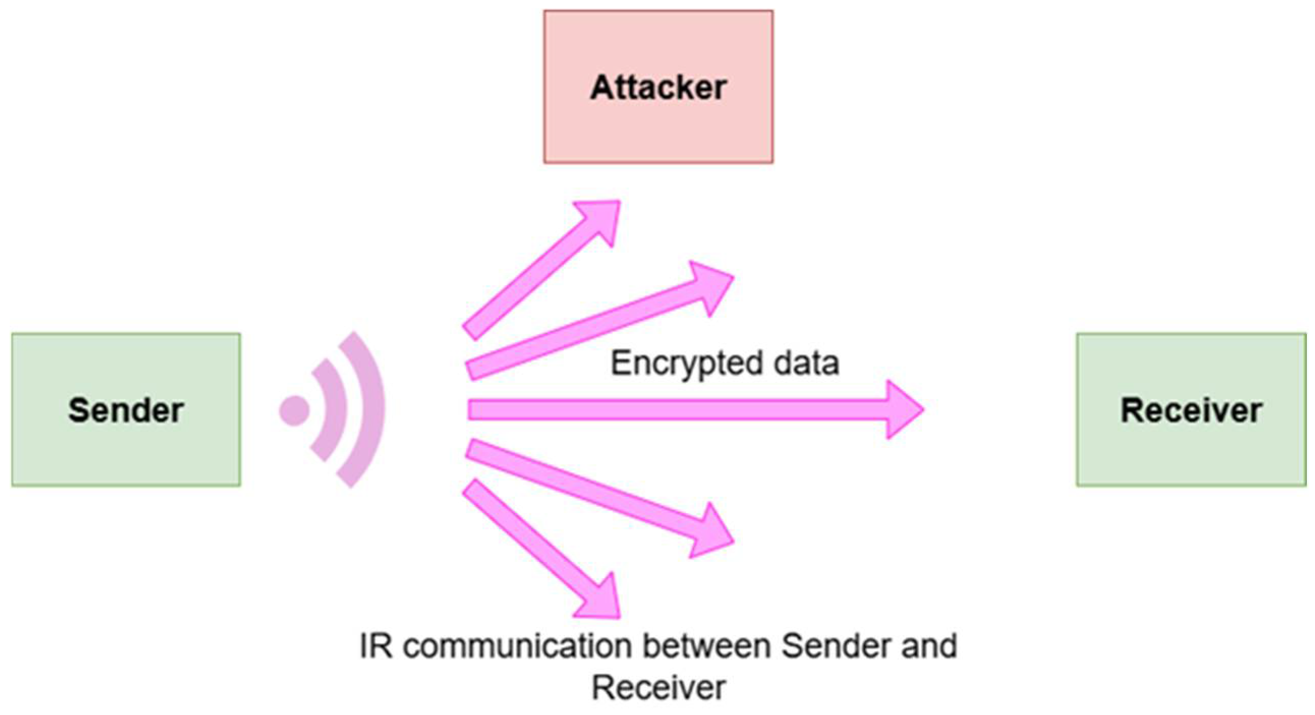
Similar to the scenario of attacking encrypted information in the electric cables of the keyboard, an attacker can eavesdrop the IR communication between the Sender and the Receiver part of the secure keyboard, by just using an IR receiver. Once again, given that the communication is end-to-end encrypted using either AES/XOR/Spritz or ECC cryptographic schemes, the attacker cannot decrypt the sent keystrokes to the end device, so it would be impossible to successfully complete their attack. Figure 32 depicts the attack scheme on the IR circuit, using block diagrams.
Figure 33 shows a demonstration of an attack on Infrared communication USB keyboard. The transmitter part receives the USB keyboard keystrokes, encrypts them via AES cipher, and transmits through the Infrared channel of the optical spectrum, specifically at 940 nm. The receiver gathers the encrypted keystrokes, decrypts them using the AES protocol, and sends them to the end PC/laptop/cloud/terminal/server. The attacker eavesdrops the IR channel in order to “catch” the transmitted packets using a common IR receiver, as analyzed in a previous section. However, the attacker does not know the AES encryption/decryption key. For this reason, the gathered packets do not contain any useful information. The results of the IR attack are demonstrated in Figure 34.

8.8. Possible Attack in the Zigbee Keyboard Communication

The attacker can use a Zigbee sniffer in order to capture Zigbee data between the sender and the receiver in the Zigbee implementation (Figure 35). Once again, the keystrokes between the sender and the receiver part are encrypted using AES with built-in configuration. The configuration of the AES encryption is realized using X-CTU software provided by Digi, which is faster than the AES encryption provided by the Arduino MEGA 2560 R3 in the aforementioned experiments. Due to the fact that the traffic is encrypted, the pressed keystrokes cannot reveal any packet the attacker might gather.

8.9. Realization of the Above Experiments in Different Modules

All the experiments in the current research paper were conducted in Arduino boards. The reason behind this decision is that those modules use open-source C/C++ code and open-source hardware, highly flexible for research purposes. There are many github repositories with open-source licenses that could be executed in Arduino boards. Arduino MEGA 2560 R3 is a very famous, easy-to-use, highly adjustable board which can support various sensors. One of the main concerns behind the decision to use Arduino was the need for a microcontroller that could “understand” keystrokes from USB keyboard. Moreover, a module that could “replicate” keystrokes (operate as USB HID—Universal Serial Bus Human Interface Device) in order to send them to the end PC/laptop/cloud/terminal was essential too.
These two prerequisites were met with the quite new Arduino GIGA R1 which has a USB input and the related C/C++ libraries in order to both detect USB keyboard keystrokes as well as produce some. The C/C++ libraries requiring encryption/decryption were the following: AES, ECC, XOR, and Spritz. They were perfectly executed in Arduino MEGA 2560 R3, 8 bit processor, with the suitable C/C++ code configured by the authors of the current research paper.
Another issue is that C/C++ is a very fast programming language closer to the CPU/hardware, in general, and not so close to the programmer as occurs with high-level programming languages, such as python. The Arduino modules used do not incorporate any complex operating system that could insert unnecessary delays. However, some ciphers (presented in previous tables) demonstrated significant delays in keystrokes.
However, there are other open-source solutions to produce the same results. One option could be the Raspberry Pi 4, which contains USB ports, so the USB keyboard can be connected to it. It also contains a UART protocol that communicates with another Raspberry Pi. The encryption can take place in one Raspberry Pi and send the keystrokes gathered from the USB keyboard to the other Raspberry Pi, which will realize the decryption and send the appropriately constructed keystrokes to the end laptop/PC/cloud/terminal.
Raspberry Pi 4 is an SBC, which stands for Single Board Computer, and some of its most important characteristics are the following [44]:
  • Broadcom BCM2711, Quad core Cortex-A72 (ARM v8) 64 bit SoC @ 1.8 GHz.
  • 1 GB, 2 GB, 4 GB, or 8 GB LPDDR4-3200 SDRAM (depending on model).
  • 2.4 GHz and 5.0 GHz IEEE 802.11ac wireless, Bluetooth 5.0, BLE.
  • Gigabit Ethernet.
  • Two USB 3.0 ports; two USB 2.0 ports.
  • Raspberry Pi standard 40 pin GPIO header.
  • Micro-SD card slot for loading operating system and data storage.
  • 5 V DC via USB-C connector (minimum: 3 Ampere).
Possible issues would be the energy consumption, since a Raspberry Pi 3/4 can draw around 400–450 mA current (tested) without anything being connected to its USB ports, neither realizing heavy processing, just a stand-by operation. Arduino MEGA 2560 R3 or Arduino GIGA R1 draw less than 100 mA current as stand-by, without performing any processing or having any sensor connected. Another issue is that libraries in C/C++ or python or any other programming language should be used to implement AES, XOR, Spritz symmetric ciphers, and ECC asymmetric cipher for encrypting/decrypting the various keystrokes input to the USB. The delay is unknown and is dependent on the programming language used for the cipher realization. As discussed above, C/C++ is fast, whereas python is a higher-level programming language and more familiar to the programmer.
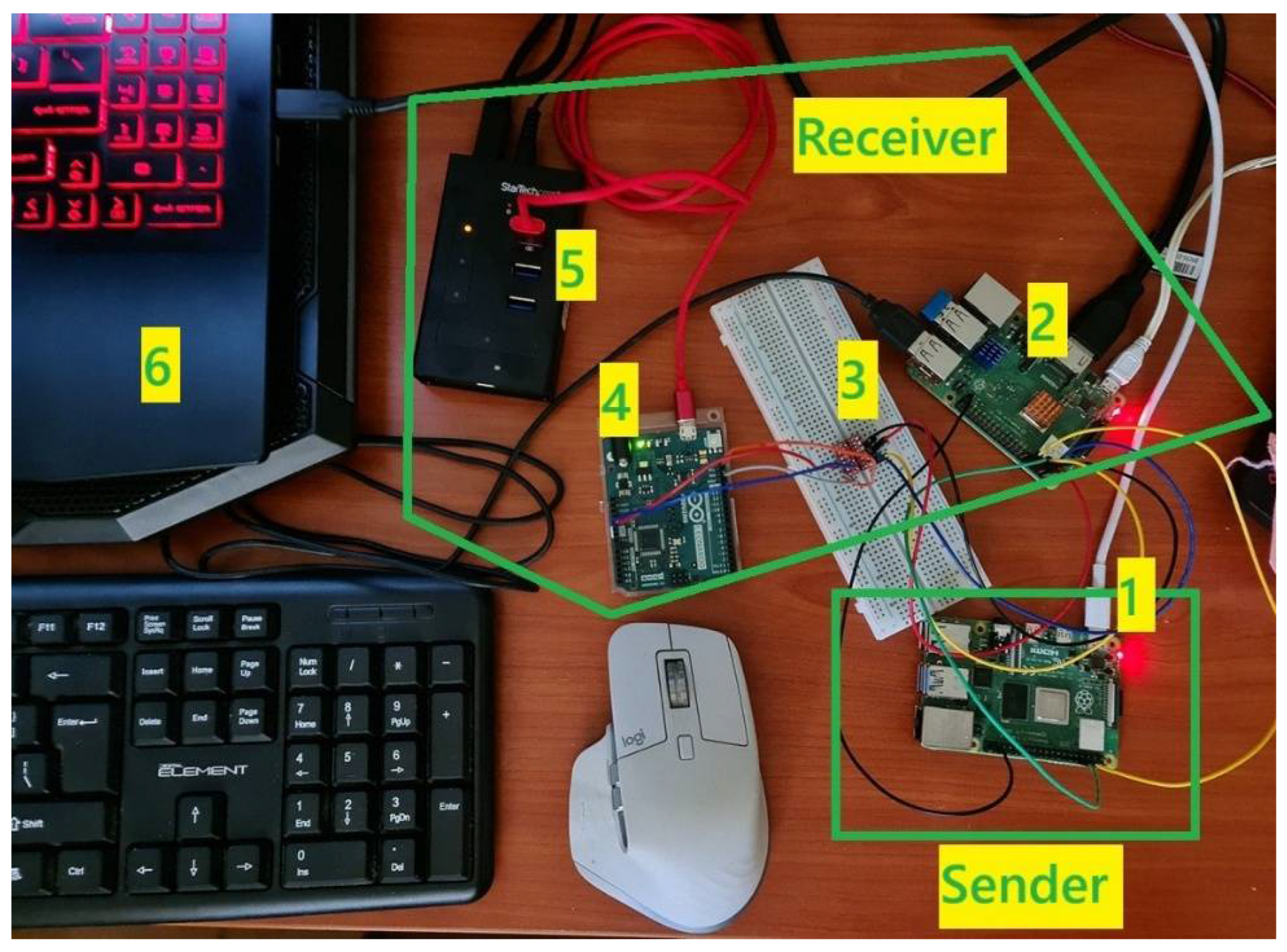
Figure 36 depicts a typical experiment using two Raspberry Pi 3/4, an Arduino Leonardo, a voltage level translator (converts 3.3 V to 5 Volt and the opposite), the USB keyboard, and the end PC/laptop/terminal/cloud. The idea in that case is that alternative modules are used, but not the mainstream Arduino presented in the previous sections. The encryption takes place on the left Raspberry Pi 3/4, which is connected to the USB keyboard. It then transmits the encrypted keystrokes, using the known UART protocol, to the right Raspberry Pi 3/4, which decrypts the data and sends them, via the suitable voltage translator, on Arduino Leonardo (which transforms the data into suitable keystroke formats). Then, Arduino Leonardo sends the formatted keystrokes to be submitted to the end PC/laptop/cloud/terminal. The encryption/decryption symmetric ciphers can be realized in any programming language, since Raspberry Pi 3/4 is based on Linux-like OS. However, it should be underlined that different programming language implementation means also different time delays in the propagation of keystrokes from the USB keyboard to the end PC/laptop/cloud/terminal.
For the current experiment, depicted in Figure 36, the following github repository was used [45], which realizes the AES encryption and decryption in python programming language. The voltage level translator is needed because Raspberry Pi 3/4 operates on 3.3 Volts logic in its pins whereas the Arduino Leonardo operates on 5 Volt logic in its pins. Arduino Leonardo acts as I2C slave, where the right Raspberry Pi 3/4 acts as I2C master. The I2C (Inter-Integrated Circuit) [46] protocol is another one, as occurs with UART, that is used for communication between various modules. It is widely used for communicating lower-speed integrated circuits (ICs) to various CPUs and microcontrollers that, most of the time, exist in short-distance, intra-board communication. The communication of the various modules on the receiver part (Raspberry Pi 3/4, level voltage translator, Arduino Leonardo, end pc/laptop/cloud/server/terminal) can be realized in a PCB, thus, decreasing the EMI/RFI emitted from the cables. The reason behind the use of Arduino Leonardo is the fact that it can support I2C slave operation as well as USB-HID, something that Raspberry Pi 3/4 cannot support.
As can be seen in Figure 37, there are all the components which were used for the experiment. Initially, there are the two parts in the secure communication, the sender and the receiver. The sender (1) gathers the keystrokes from the USB keyboard and encrypts them using AES cipher. The data are then sent to the other Raspberry Pi 4 via UART protocol. The receiver Raspberry Pi 3B+ (2) decrypts the data and propagates them to Arduino Leonardo (4) via the voltage level translator (4). The output of the Arduino Leonardo (5) propagates the decrypted keystrokes to the end device (6). For the current experiment, the output (5) sends the data in the Arduino terminal, but it was obviously tested to a second end device/laptop in order to check the current operation, where it was successfully fed with decrypted keystrokes .docx and .txt files. Both Raspberry Pi (4B and 3B+), execute python programs in order to gather the input and encrypt the data (1) as well as to read the encrypted data from the UART, decrypt them, and transmit them over the I2C to Arduino Leonardo. In order to control better the two Raspberry Pi, SSH connection was used in order to upload the various python scripts and make the appropriate configurations, such as to enable SSH, UART, and I2C interfaces. Both Raspberry Pi 4 and Raspberry Pi 3B+ contain the same interfaces in the specific pins that were used for the experiments.

9. Conclusions

To sum up, the research presented in this paper proposes new types of keyboards, which can send secure keystrokes to the PC/laptop/terminal/server/cloud which, instead of the traditional USB copper wired keyboard, might be using either a fiber optic cable with a pair of electro-optic transceivers, or wired encrypted (AES, ECC, XOR, or Spritz), or encrypted IR communication, or wireless modules (Zigbee) over encrypted links and a pair of Arduino operating according to the USB protocol. According to the literature, the classic USB-wired keyboards as well as the unencrypted wireless ones are vulnerable to eavesdropping attacks due to their emitted EMI/RFI signals. As a result, eavesdropping attacks to keyboards will not be successful according to the proposed mechanisms in this paper. Of course, all of the above experimental circuits show a potential solution. In case they are to be commercialized, the cables should be replaced by wires on a PCB, and the Arduino modules with microcontrollers on the PCB. In such kind of situations, methods that do not let EM “leave” the electrical circuits should be realized.
Another issue was the difficulty of the experiments ranging from simple C/C++ code execution in Arduino GIGA R1 to an easy hardware construction using fiber optic transceivers, or medium difficulty such as IR-encrypted free-space communication, or AES and ECC encryption and decryption schemes running in Arduino MEGA 2560 R3.
It is important to underline the fact that the potential solutions presented in the current paper investigate only the means of transmitting the keystrokes, and not any other side-channel attacks that can take place in the CPU, for example, or any other electronic component.
Another solution that could be realized in the future concerning the security of the transmission between the USB keyboard and the end device/laptop/cloud/edge could be the use of a laser link. A 5 mW red laser module at 650 nm or a green laser module at 532 nm could transfer the keystrokes from the USB keyboard to the end device. Semiconductor laser modules seem to be preferable because they are easy to use. Laser links are difficult to be eavesdropped on from an adversary since the laser link would be disconnected. Contrary to laser link, as proposed in the current research paper, IR link can be easily eavesdropped on with an inexpensive IR receiver if there is no encryption. That is why AES cryptographic algorithm was used.
The types of keyboards presented in the current research work can be used in critical fields, such as banks, ministries, or military fields where critical input is given by the users to the cloud/end pc/terminal/server via the use of USB keyboards, making it impossible for an attacker to extract significant information. In the current work, there was no calculation of the effective distance that an attacker can extract keystrokes. However, there are plenty of similar references in the literature.

Author Contributions

Conceptualization, G.R. and I.R.; methodology, G.R. and I.R.; software, G.R.; validation, G.R. and I.R.; formal analysis, G.R.; investigation, G.R.; writing—original draft preparation, G.R.; writing—review and editing, G.R. and I.R.; supervision, I.R.; project administration, I.R. All authors have read and agreed to the published version of the manuscript.

Funding

This research received no external funding.

Data Availability Statement

The datasets presented in this article are not readily available because the data are part of an ongoing study. Requests to access the datasets should be directed to the authors.

Conflicts of Interest

The authors declare no conflicts of interest.

References

  1. Jin, W.; Murali, S.; Zhu, H.; Li, M. Periscope: A Keystroke Inference Attack Using Human Coupled Electromagnetic Emanations. In Proceedings of the 2021 ACM SIGSAC Conference on Computer and Communications Security, New York, NY, USA, 15–19 November 2021; Association for Computing Machinery: New York, NY, USA, 2021; pp. 700–714. [Google Scholar]
  2. Wang, L.; Yu, B. Analysis and Measurement on the Electromagnetic Compromising Emanations of Computer Keyboards. In Proceedings of the 2011 Seventh International Conference on Computational Intelligence and Security, Sanya, China, 3–4 December 2011; pp. 640–643. [Google Scholar]
  3. Choi, H.-J.; Lee, H.S.; Sim, D.; Yook, J.-G.; Sim, K. Reconstruction of Leaked Signal from USB Keyboards. In Proceedings of the 2016 URSI Asia-Pacific Radio Science Conference (URSI AP-RASC), Seoul, Republic of Korea, 21–25 August 2016; IEEE: New York, YN, USA, 2016; pp. 1281–1283. [Google Scholar]
  4. Vuagnoux, M.; Pasini, S. An Improved Technique to Discover Compromising Electromagnetic Emanations. In Proceedings of the 2010 IEEE International Symposium on Electromagnetic Compatibility, Fort Lauderdale, FL, USA, 25–30 July 2010; pp. 121–126. [Google Scholar]
  5. Chen, B.; Yenamandra, V.; Srinivasan, K. Tracking Keystrokes Using Wireless Signals. In Proceedings of the 13th Annual International Conference on Mobile Systems, Applications, and Services, Florence, Italy, 18–22 May 2015; Association for Computing Machinery: New York, NY, USA, 2015; pp. 31–44. [Google Scholar]
  6. Hu, J.; Wang, H.; Zheng, T.; Hu, J.; Chen, Z.; Jiang, H.; Luo, J. Password-Stealing without Hacking: Wi-Fi Enabled Practical Keystroke Eavesdropping. In Proceedings of the 2023 ACM SIGSAC Conference on Computer and Communications Security, Copenhagen, Denmark, 26–30 November 2023; Association for Computing Machinery: New York, NY, USA, 2023; pp. 239–252. [Google Scholar]
  7. Chen, Y.; Yu, J.; Chen, Y.; Kong, L.; Zhu, Y.; Chen, Y.-C. RFSpy: Eavesdropping on Online Conversations with Out-of-Vocabulary Words by Sensing Metal Coil Vibration of Headsets Leveraging RFID. In Proceedings of the 22nd Annual International Conference on Mobile Systems, Applications and Services, Tokyo, Japan, 3–7 June 2024; Association for Computing Machinery: New York, NY, USA, 2024; pp. 169–182. [Google Scholar]
  8. Choi, D.-H.; Lee, E.; Yook, J.-G. Reconstruction of Video Information Through Leakaged Electromagnetic Waves From Two VDUs Using a Narrow Band-Pass Filter. IEEE Access 2022, 10, 40307–40315. [Google Scholar] [CrossRef]
  9. Hayashi, Y.-I.; Homma, N.; Watanabe, T.; Price, W.O.; Radasky, W.A. Introduction to the Special Section on Electromagnetic Information Security. IEEE Trans. Electromagn. Compat. 2013, 55, 539–546. [Google Scholar] [CrossRef]
  10. Lee, H.S.; Choi, D.H.; Sim, K.; Yook, J.-G. Information Recovery Using Electromagnetic Emanations From Display Devices Under Realistic Environment. IEEE Trans. Electromagn. Compat. 2019, 61, 1098–1106. [Google Scholar] [CrossRef]
  11. Eltholth, A.A. Improved Spectrum Coexistence in 2.4 GHz ISM Band Using Optimized Chaotic Frequency Hopping for Wi-Fi and Bluetooth Signals. Sensors 2023, 23, 5183. [Google Scholar] [CrossRef] [PubMed]
  12. Bari, M.F.; Chowdhury, M.R.; Sen, S. Is Broken Cable Breaking Your Security? In Proceedings of the 2023 IEEE International Symposium on Circuits and Systems (ISCAS), Monterey, CA, USA, 21–25 May 2023; pp. 1–5. [Google Scholar]
  13. Wireshark • Undefined. Available online: https://www.wireshark.org/ (accessed on 20 June 2025).
  14. Landman, D. DavyLandman/AESLib 2025. Available online: https://github.com/DavyLandman/AESLib (accessed on 20 June 2025).
  15. ShubhamAnnigeri ShubhamAnnigeri/tinyECC-ArduinoIDE 2024. Available online: https://github.com/ShubhamAnnigeri/tinyECC-ArduinoIDE (accessed on 20 June 2025).
  16. Kelasrobot/SimpleArduinoEncryption 2025. Available online: https://github.com/kelasrobot/SimpleArduinoEncryption (accessed on 3 October 2025).
  17. Adjal, A. Abderraouf-Adjal/ArduinoSpritzCipher 2025. Available online: https://github.com/abderraouf-adjal/ArduinoSpritzCipher (accessed on 3 October 2025).
  18. Babani, S.; Bature, A.A.; Faruk, M.I.; Dankadai, N.K. Comparative study between fiber optic and copper in communication link. Int. J. Tech. Res. Appl. 2014, 2, 59–63. [Google Scholar]
  19. López-Cardona, J.D.; Vázquez, C.; Montero, D.S.; Lallana, P.C. Remote Optical Powering Using Fiber Optics in Hazardous Environments. J. Light. Technol. 2018, 36, 748–754. [Google Scholar] [CrossRef]
  20. Gravity: UART Fiber Optic Transceiver Module Wiki—DFRobot. Available online: https://wiki.dfrobot.com/SKU_TEL0153_Gravity_UART_Fiber_Optic_Transceiver_Module (accessed on 20 June 2025).
  21. Al-fatlawi, A.H.; Abdul Zahra, M.M.; Rassool, H.A. Simulation of Optical Fiber Cable Regarding Bandwidth Limitations. Int. J. Nonlinear Anal. Appl. 2021, 12, 1159–1174. [Google Scholar]
  22. Abdullah, A.M. Advanced Encryption Standard (AES) Algorithm to Encrypt and Decrypt Data. Cryptogr. Netw. Secur. 2017, 16, 11. [Google Scholar]
  23. Hamza, A.; Kumar, B. A Review Paper on DES, AES, RSA Encryption Standards. In Proceedings of the 2020 9th International Conference System Modeling and Advancement in Research Trends (SMART), Moradabad, India, 4–5 December 2020; IEEE: New York, YN, USA, 2020; pp. 333–338. [Google Scholar]
  24. Paar, C.; Pelzl, J.; Güneysu, T. Understanding Cryptography: From Established Symmetric and Asymmetric Ciphers to Post-Quantum Algorithms; Springer: Berlin/Heidelberg, Germany, 2024; ISBN 978-3-662-69006-2. [Google Scholar]
  25. Ramya, C.M.; Shanmugaraj, M.; Prabakaran, R. Study on ZigBee Technology. In Proceedings of the 2011 3rd International Conference on Electronics Computer Technology, Kanyakumari, India, 8–10 April 2011; Volume 6, pp. 297–301. [Google Scholar]
  26. Zigbee. Wikipedia 2024. Available online: https://en.wikipedia.org/w/index.php?title=Zigbee&oldid=1246713824 (accessed on 20 June 2025).
  27. WRL-08665 SparkFun | Mouser Greece. Available online: https://gr.mouser.com/ProductDetail/SparkFun/WRL-08665?qs=WyAARYrbSnbfBpB%252BN4iLCg%3D%3D&srsltid=AfmBOoqllDf-ZNZjEni8rEI2chgCx1QDcxFAwLy_7ZpTaL_BYhWPofLX (accessed on 20 June 2025).
  28. SparkFun XBee 2mW Wire Antenna—Series 2 (ZigBee Mesh): Amazon.in: Computers & Accessories. Available online: https://www.amazon.in/XBee-2mW-Wire-Antenna-ZigBee/dp/B007R9U1QA (accessed on 20 June 2025).
  29. Digi International XBee Pro 63mW Wire Antenna—Series 2B (ZigBee Mesh): Amazon.Co.Uk: Electronics & Photo. Available online: https://www.amazon.co.uk/XBee-Pro-63mW-Wire-Antenna/dp/B00Q6Y79W6 (accessed on 20 June 2025).
  30. Adi, P.D.P.; Sihombing, V.; Siregar, V.M.M.; Yanris, G.J.; Sianturi, F.A.; Purba, W.; Tamba, S.P.; Simatupang, J.; Arifuddin, R.; Subairi, S.; et al. A Performance Evaluation of ZigBee Mesh Communication on the Internet of Things (IoT). In Proceedings of the 2021 3rd East Indonesia Conference on Computer and Information Technology (EIConCIT), Surabaya, Indonesia, 9–11 April 2021; pp. 7–13. [Google Scholar]
  31. Industries, A. XBee Module—ZB Series S2C—2mW with Wire Antenna. Available online: https://www.adafruit.com/product/968 (accessed on 3 October 2025).
  32. Willner, A.E.; Zhou, H.; Duan, Y.; Jiang, Z.; Ramakrishnan, M.; Su, X.; Zou, K.; Pang, K. Advances in Multi-Channel Mid-IR Free-Space Optical Communications. J. Light. Technol. 2024, 42, 6739–6748. [Google Scholar] [CrossRef]
  33. Zhu, Y.; Chen, H.; Han, R.; Qin, H.; Yao, Z.; Liu, H.; Ma, Y.; Wan, X.; Li, G.; Chen, Y. High-Speed Flexible near-Infrared Organic Photodiode. Natl. Sci. Rev. 2023, 11, nwad311. [Google Scholar] [CrossRef] [PubMed]
  34. Zhong, R.; Ji, J.; Zeng, T.; Wang, K.; Song, Y. Performance Analysis of Physical-Layer Security in Mid-Infrared FSO Communication System. Opt. Quantum Electron. 2024, 56, 463. [Google Scholar] [CrossRef]
  35. Use Multiple Serial Ports on the Arduino Mega | Arduino Documentation. Available online: https://docs.arduino.cc/built-in-examples/communication/MultiSerialMega/ (accessed on 20 June 2025).
  36. Arduino GIGA R1 User Manual | Arduino Documentation. Available online: https://docs.arduino.cc/tutorials/giga-r1-wifi/cheat-sheet/ (accessed on 20 June 2025).
  37. Moreira, A.J.C.; Valadas, R.T.; De Oliveira Duarte, A.M. Optical Interference Produced by Artificial Light. Wirel. Netw. 1997, 3, 131–140. [Google Scholar] [CrossRef]
  38. Park, T.-J.; Kim, K.; Moon, S. Securing Infrared Communication in Nuclear Power Plants: Advanced Encryption for Infrared Sensor Networks. Sensors 2024, 24, 2054. [Google Scholar] [CrossRef] [PubMed]
  39. Kim, M.; Suh, T. Eavesdropping Vulnerability and Countermeasure in Infrared Communication for IoT Devices. Sensors 2021, 21, 8207. [Google Scholar] [CrossRef] [PubMed]
  40. AS7341 Spectral Color Sensor—Waveshare Wiki. Available online: https://www.waveshare.com/wiki/AS7341_Spectral_Color_Sensor (accessed on 3 October 2025).
  41. Device.Report Ams AS7341 Sensor Chip User Guide. Available online: https://device.report/manual/8764433 (accessed on 3 October 2025).
  42. Mega 2560 Rev3 | Arduino Documentation. Available online: https://docs.arduino.cc/hardware/mega-2560/ (accessed on 3 October 2025).
  43. Arduino GIGA R1 WiFi. Available online: https://store.arduino.cc/products/giga-r1-wifi (accessed on 3 October 2025).
  44. Ltd, R.P. Raspberry Pi 4 Model B Specifications. Available online: https://www.raspberrypi.com/products/raspberry-pi-4-model-b/specifications/ (accessed on 3 October 2025).
  45. BoppreH Boppreh/Aes 2025. Available online: https://github.com/boppreh/aes (accessed on 20 September 2025).
  46. I2C. Wikipedia 2025. Available online: https://en.wikipedia.org/w/index.php?title=I%C2%B2C&oldid=1312382986 (accessed on 5 October 2025).
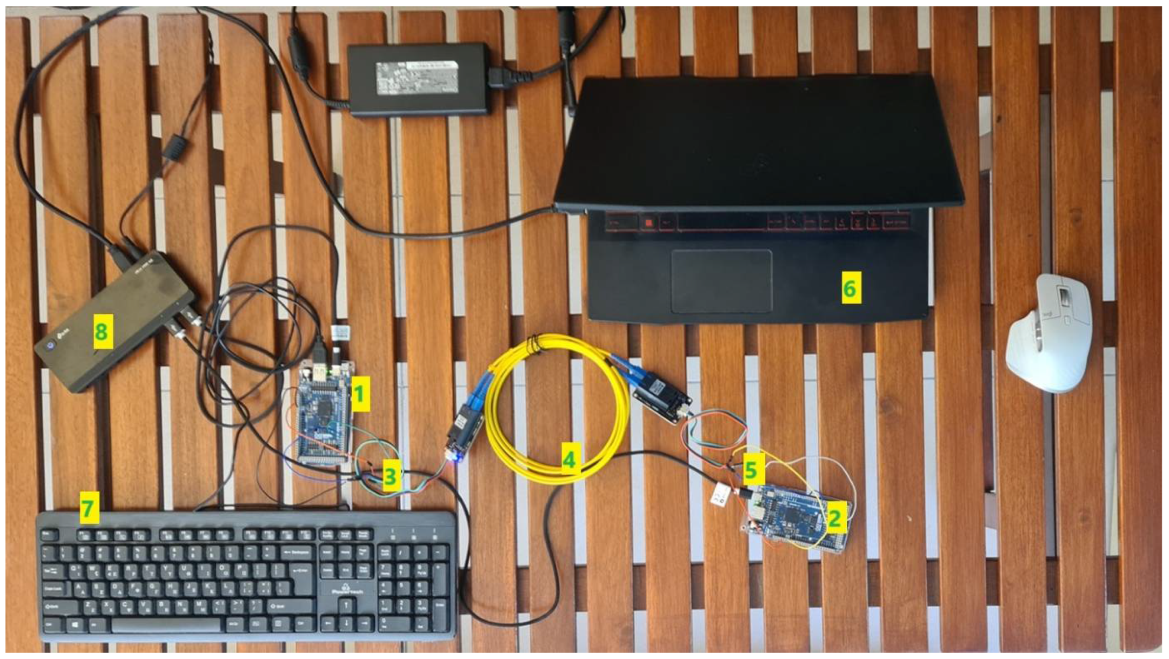
Figure 1. Experimental constructure using two Arduino GIGA R1s, two Fiber Optic Transceiver Modules, and a fiber optic cable in order to send keystrokes from the USB keyboard to the end PC/laptop.
Telecom 06 00085 g001
Figure 2. Block diagram of the USB keyboard experiment, using fiber optic cable.
Telecom 06 00085 g002
Figure 3. Diagram of the different modules and the connections among them in order to transmit encrypted keystrokes.
Telecom 06 00085 g003
Figure 4. Experimental demonstration of the two Arduino GIGA R1s, two Arduino MEGA 2560 R3s, two bidirectional level translators, and their UART connections in order to transmit encrypted keystrokes from the USB keyboard to the end device.
Telecom 06 00085 g004
Figure 5. Thermal imaging from Arduinos operating on modified ECC protocol. As it is seen in the image there are 2 numbers indicating the actual temperatures. With the green color; 22.6 °C is the lower temperature and with the red color; 41.0 °C is the highest temperature.
Telecom 06 00085 g005
Figure 6. Simple XOR encryption/decryption for the secure USB keyboard.
Telecom 06 00085 g006
Figure 7. Different networks of a Zigbee network [25].
Telecom 06 00085 g007
Figure 8. Demonstration of the data sent from the Zigbee Router in text and the related hexadecimal format.
Telecom 06 00085 g008
Figure 9. Demonstration of the data received from the Zigbee Router in text and the related hexadecimal format.
Telecom 06 00085 g009
Figure 10. In order to enable encryption, the following flag “EE” should be set to “1”, and one must also insert the encryption key.
Telecom 06 00085 g010
Figure 11. Presentation of the Zigbee modules while operating. The Arduino GIGA R1, the two Zigbee Xbee 2 mW, the USB keyboard, the power supply, and the end PC/laptop are depicted.
Telecom 06 00085 g011
Figure 12. This is the text sent by the USB keyboard via the Arduino GIGA R1 and the two Zigbees.
Telecom 06 00085 g012
Figure 13. Zigbee communication using AES encryption between the two Xbee Zigbees.
Telecom 06 00085 g013
Figure 14. Demonstration diagram of the USB keyboard sending keystrokes to the end PC/laptop, via the two Arduino GIGA R1 and the Zigbee wireless connection with the help of level translators.
Telecom 06 00085 g014
Figure 15. Testing the IR link with two Arduino MEGA 2560 R3 over the UARTs.
Telecom 06 00085 g015
Figure 16. IR communication block diagram. The purple arrow demonstrates the encrypted data, sent from the IR emitter to the IR receiver.
Telecom 06 00085 g016
Figure 17. Presentation of a part of pulses sent from the IR transmitter, representing an encrypted message.
Telecom 06 00085 g017
Figure 18. Unencrypted communication for the USB keyboard where (1) indicates the transmitting hardware part and (2) indicates the receiver elements.
Telecom 06 00085 g018
Figure 19. It is depicted which UART each C/C++ command controls in Arduino GIGA R1 [36].
Telecom 06 00085 g019
Figure 20. Circuit for testing the UARTs of the two Arduino GIGA R1s and the two Arduino MEGA 2560 R3s, via the two level translators.
Telecom 06 00085 g020
Figure 21. C/C++ code running on Arduino IDE for testing the UARTs of the Arduinos with the bidirectional level translators. (1) depicts the code for sending message to Serial 4 of Arduino GIGA R1. (2) depicts the code for reading from Serial 2 and sending the data to Serial 1 of Arduino MEGA 2560 R3. (3) shows the code for reading from Serial 1 and sending them to Serial 2 of Arduino MEGA 2560 R3. (4) shows the code for reading data from Serial 4 and sending them to Serial 0 (USB) of Arduino GIGA R1.
Telecom 06 00085 g021
Figure 22. Received message at the end Arduino GIGA R1, sent from the Arduino GIGA R1 connected to the USB keyboard. There are no errors, such as “garbage”, indicating that the UARTs cooperate without any problems.
Telecom 06 00085 g022
Figure 23. IR emitter (1) and IR receiver (2) of the IR communication experiment.
Telecom 06 00085 g023
Figure 24. “Garbage” received in the IR receiver when the IR transmitter and IR receiver are not aligned.
Telecom 06 00085 g024
Figure 25. The raw values of the different optical channels, as measured by the AS7341 chip.
Telecom 06 00085 g025
Figure 26. Mapping configuration table of ECC C/C++ library.
Telecom 06 00085 g026
Figure 27. Comparison of the power consumption of the different secure USB keyboard schemes.
Telecom 06 00085 g027
Figure 28. (a) shows the response when attaching the electric EMC probe to the fiber optic cable, (b) shows the electric near-field EMC probe, (c) depicts the response of the spectrum analyzer when placing the electric near-field EMC probe on the USB cable, (d) shows the electric EMC probe placed on the USB cable, (e) depicts the magnetic near-field EMC probe and the response of the spectrum analyzer, when placed on the fiber optic cable, and (f) depicts the response in the spectrum analyzer when placing the magnetic near-field EMC probe on the USB cable.
Telecom 06 00085 g028
Figure 29. This image demonstrates an attack in the keyboards cable, which contains the encrypted keystrokes, either using AES or ECC protocols. The sending part and the receiving part are depicted in green rectangles, and the attacker is depicted in red rectangle. The idea is that the attacker eavesdrops data.
Telecom 06 00085 g029
Figure 30. The keystrokes pressed in the USB keyboard are depicted in place “1”, while the data gathered by the attacker are depicted in the place “2”. As it is obvious, the data are encrypted (with AES), so they are useless to the attacker.
Telecom 06 00085 g030
Figure 31. Similar to the AES encryption, this figure shows that there is ECC encryption. The attacker gathers encrypted keystrokes which are useless. Of course, the encryption results are different since ECC and AES have different algorithmic approach on how to encrypt/decrypt a message.
Telecom 06 00085 g031
Figure 32. Demonstration of how a possible attack with IR receiver can take place in the IR connection between the sending and the receiving part of the USB keyboard. Once again, the attacker eavesdrops data using and IR receiver; however, the keystrokes are encrypted (either using AES/XOR/Spritz or ECC), so they are useless.
Telecom 06 00085 g032
Figure 33. The IR attacker circuit: the sender, the receiver, and the attacker hardware.
Telecom 06 00085 g033
Figure 34. Eavesdropped data collected by the attacker during IR communication.
Telecom 06 00085 g034
Figure 35. Zigbee realization using fast AES encryption provided by the Xbee Zigbee. The attacker cannot decrypt the traffic given that the AES encryption key is strong.
Telecom 06 00085 g035
Figure 36. Alternative realization using two Raspberry Pi 3/4, instead of the four Arduino. The encryption takes place in the left Raspberry Pi 3/4, whereas the decryption in the right Raspberry Pi 3/4.
Telecom 06 00085 g036
Figure 37. The actual construction of the Raspberry Pi 4 and Arduino Leonardo experiment with the various connections.
Telecom 06 00085 g037
Table 1. This is a table consisting of all the proposed solutions, the communication method, whether encryption is used, the used encryption scheme, the difficulty level related to software/hardware configuration, and the bandwidth (either measured or provided by the manufacturer).
Proposed SolutionCommunication TypeEncryption Used (Y/N)Encryption ProtocolConfiguration Difficulty (Software and Hardware)Experiment Cost (Without Laptop and Mouse) in EurosScalabilityBandwidth
1IR light (fiber optic cable)No-1234.56Medium2 Mbps
2WireYesAES2353.96Medium500 kbps (limited due to Arduino MEGA 2560 R3)
3WireYesECC2353.96Medium500 kbps (limited due to Arduino MEGA 2560 R3)
4WireYesXOR2353.96Medium500 kbps (limited due to Arduino MEGA 2560 R3)
5WireYesSpritz2353.96Medium500 kbps (limited due to Arduino MEGA 2560 R3)
6Wireless (Zigbee)—one Arduino GIGA R1YesAES2167.25High250 kbps max (provided by the manufacturer)
7Free-space IR communicationYesAES2374.56Medium9600 bps (tested)
Table 2. Comparison table of the four different cryptographic protocols executed on Arduino MEGA 2560 R3.
AlgorithmEncryption Time (ms)Decryption Time (ms)
ECC48642218.5
AES0.2860.3256
XOR0.1810.696
Spritz0.1160.116
Table 3. Sum up of the delay (in seconds) for each secure keyboard scheme.
SchemeDelay (in Seconds)
Arduinos with AES encryption/decryption circuit4
Arduinos with ECC encryption/decryption circuit6
Arduinos with XOR encryption/decryption circuit4
Arduinos with Spritz encryption/decryption circuit3
Arduinos circuit with fiber optic (no Arduino MEGA 2560 R3 used)1
Arduinos circuit with IR LED communication4
Arduinos with Zigbee communication (no Arduino MEGA 2560 R3 used)1
Disclaimer/Publisher’s Note: The statements, opinions and data contained in all publications are solely those of the individual author(s) and contributor(s) and not of MDPI and/or the editor(s). MDPI and/or the editor(s) disclaim responsibility for any injury to people or property resulting from any ideas, methods, instructions or products referred to in the content.