Article

Slotted Circular-Patch MIMO Antenna for 5G Applications at Sub-6 GHz

1
Electrical Engineering Department, Faculty of Engineering, Suez Canal University, Ismailia 41522, Egypt
2
Microstrip Department, Electronics Research Institute, New Nozha, Cairo 11843, Egypt
3
Computer, Electrical, and Mathematical Sciences and Engineering (CEMSE) Division, King Abdullah University of Science and Technology (KAUST), Thuwal 23955-6900, Saudi Arabia
4
Department of Electronics and Communications Engineering, Egypt-Japan University of Science and Technology, New Borg El-Arab City 21934, Egypt
5
Department of Electrical and Electronics Engineering, Assiut University, Assiut 71515, Egypt
*
Author to whom correspondence should be addressed.
Telecom 2025, 6(3), 53; https://doi.org/10.3390/telecom6030053
Submission received: 19 May 2025 / Revised: 12 July 2025 / Accepted: 15 July 2025 / Published: 28 July 2025

Abstract

The swift advancement of fifth-generation (5G) wireless technology brings forth a range of enhancements to address the increasing demand for data, the proliferation of smart devices, and the growth of the Internet of Things (IoT). This highly interconnected communication environment necessitates using multiple-input multiple-output (MIMO) systems to achieve adequate channel capacity. In this article, a 2-port MIMO system using two flipped parallel 1 × 2 arrays and a 2-port MIMO system using two opposite 1 × 4 arrays designed and fabricated antennas for 5G wireless communication in the sub-6 GHz band, are presented, overcoming the limitations of previous designs in gain, radiation efficiency and MIMO performance. The designed and fabricated single-element antenna features a circular microstrip patch design based on ROGER 5880 (RT5880) substrate, which has a thickness of 1.57 mm, a permittivity of 2.2, and a tangential loss of 0.0009. The 2-port MIMO of two 1 × 2 arrays and the 2-port MIMO of two 1 × 4 arrays have overall dimensions of 132 × 66 × 1.57 mm3 and 140 × 132 × 1.57 mm3, respectively. The MIMO of two 1 × 2 arrays and MIMO of two 1 × 4 arrays encompass maximum gains of 8.3 dBi and 10.9 dBi, respectively, with maximum radiation efficiency reaching 95% and 97.46%. High MIMO performance outcomes are observed for both the MIMO of two 1 × 2 arrays and the MIMO of two 1 × 4 arrays, with the channel capacity loss (CCL) ˂ 0.4 bit/s/Hz and ˂0.3 bit/s/Hz, respectively, an envelope correlation coefficient (ECC) ˂ 0.006 and ˂0.003, respectively, directivity gain (DG) about 10 dB, and a total active reflection coefficient (TARC) under −10 dB, ensuring impedance matching and effective mutual coupling among neighboring parameters, which confirms their effectiveness for 5G applications. The three fabricated antennas were experimentally tested and implemented using the MIMO Application Framework version 19.5 for 5G systems, demonstrating operational effectiveness in 5G applications.

1. Introduction

In the past decade, advanced wireless systems have revolutionized our daily lives, making technology an integral part of connecting and communicating [1]. This astounding evolution has enabled us to enjoy higher data rates, allowing seamless streaming, gaming, and browsing experiences. However, maximizing bandwidth is crucial for optimizing transmission rates [2].
The rapid growth in demand for internet speed and mobile data presents critical challenges for modern wireless systems [3]. Fifth-generation (5G) technology is designed to meet these demands, allowing countless users to connect simultaneously, significantly expanding network capacity, and delivering breathtaking data rates in gigabits per second (Gbps). Furthermore, 5G reduces latency to milliseconds and offers cost-efficient solutions for service providers [4].
To facilitate this revolutionary communication standard, the International Telecommunication Union (ITU) has two identified essential microwave bands, the sub-6 GHz band, and millimeter-wave (mm-wave) [5]. Fading and low signal-to-noise ratios remain hurdles for mm-wave communication.
Key sub-6 GHz bands for 5G encompass N77 at 3.7 GHz, N78 at 3.5 GHz, and N79 at 4.7 GHz [6]. Sub-6 GHz operates across three distinct frequency bands: the Low Band (sub-1 GHz) for extensive coverage, the High Band, featuring cutting-edge millimeter-wave (mm-wave) technology that delivers exceptional capacity and the Mid Band (sub-6 GHz), which strikes an optimal balance between coverage and capacity; and the sub-6 GHz band is particularly powerful, as it effectively confronts the challenges of both capacity and coverage [7,8,9]. This makes it not just an option, but a cornerstone for the future of connectivity, ensuring that we stay connected in an increasingly digital world [10]. Fifth-generation technology relies heavily on MIMO (multiple-input multiple-output) and array antennas to enhance coverage and increase data transmission rates, facilitating beamforming and allowing a single signal to reach its destination through multiple paths, ensuring strong and reliable connectivity for users.
MIMO antennas, which utilize multiple transmitting and receiving antennas, are becoming increasingly popular in WLAN applications [11]. They significantly enhance channel capacity and data rates without demanding additional spectrum or power, even in complex multipath fading environments. Therefore, implementing MIMO antennas in limited spaces is a superior solution for boosting transmission capacity and overcoming the challenges posed by multipath fading, ultimately paving the way for a more connected and efficient future [12].
In ref. [13], an antenna array consisting of eight elements with a total size of 136 × 68 mm2, based on an inverted-F antenna, is identified as suitable for 5G mobile applications. The array coverage for the bands n77, n78, and n79 has an ECC of less than 0.1.
In ref. [14], the antenna design is integrated with cognitive radio, benefiting from the orthogonal arrangement of its elements, which significantly enhances port isolation. While the use of reflectors also improves isolation, it does come with the trade-off of increasing the overall size of the antenna system. In ref. [15], a compact C-shaped antenna measuring 20 mm × 15 mm has been designed for WLAN and 5G applications. Although its small size is advantageous for 5G, its scattering characteristics measured at −6 dB fall short of industry standards, especially with evolving regulations such as IEEE 802.11ax. The insufficient gain of this antenna renders it unsuitable for 5G wireless requirements. Therefore, it is essential to prioritize the design of antennas that achieve a sufficient gain to meet the demands of next-generation communication systems. In ref. [16], the eight-element antenna array, measuring 136 × 68 mm2 and based on an inverted-F design, is suitable for 5G mobile applications. The array covers the n77, n78, and n79 bands, with an ECC of less than 0.1. This design achieves an efficiency rate of 70%.
In ref. [17], a four-MIMO array design for 5G mobile systems measures 150 mm by 75 mm and operates across three bands in the sub-6 GHz range. This design achieves an efficiency rate of 60%. Furthermore, reference [18] introduces an innovative transmission-line-based decoupling method that significantly boosts isolation between co-polarized elements by 16–20 dB for MIMO antenna arrays operating at 2.4 GHz.
As we move toward a fully integrated 5G infrastructure, including indoor access points, we must uphold 5G connection standards, particularly in indoor environments where signal levels are inadequate, as highlighted in reference [19]. Most contemporary solutions employ dual-polarized antennas, which offer orthogonal and low-correlated radiation patterns—critical characteristics for enhancing the performance of MIMO antennas.
In ref. [20], the author has proposed a groundbreaking miniaturized MIMO design that operates at 3.2 GHz to 3.9 GHz, covering the WiMAX, LTE, Wi-Fi, and cognitive radio applications, and with overall dimensions of 60 × 120 × 1.56 mm3, based on FR4 substrate. Its design cleverly positions the biasing circuitry and Microstrip feeding lines on the top layer, while the bottom layer—the reference ground plane—features expertly engineered pentagonal radiating slots. This closed slot-line design on the lower substrate effectively responds to reactive loading. The decision to employ a pentagonal slot line stems from its exceptional impedance matching, outstanding radiation qualities, optimal size, and ease of reactive loading. Moreover, integrating a defective ground structure (DGS) significantly elevates the isolation between adjacent antennas, ensuring superior performance and reliability in complex environments.
A triple-port antenna designed with a monopole structure and two orthogonal dipoles is discussed in reference [21]. The increasing demand for MIMO capabilities is essential for enhancing data rates in 5G indoor base stations, necessitating antennas that provide high isolation and low ECC. Additionally, reference [22] presents a four-port wideband antenna operating in the 3.3 to 5 GHz range, while reference [23] introduces a four-port cavity-backed antenna for MIMO applications, evaluating the coupling between the ports. MIMO bandwidth ranges from 1.55 to 6 GHz, achieving gain ranging from 4 dBi to 10 dBi. A compact, two-port dual-circularly polarized MIMO antenna for WLAN applications is presented in ref. [24], and the gain is in good agreement with simulation results. Tapered-width stubs and different-width slot structures have been adopted to enhance the isolation and enlarge the impedance matching bandwidth, offering gain of 8 dBi over a narrow band of 2.4 to 2.5 GHz. In ref. [25], a concept of circular polarization agility is presented with two antennas operating in the sub-6 GHz band. Two cylindrical and ring DRA prototypes with dual-port MIMO on ROGER 5870 of octagonal shape operate at bandwidths of 3.15–3.9 GHz and 3.12–3.9 GHz, respectively, offering 7.3 dBi gain. The circular design in ref. [26] uses ROGER R04003C and features four ports. Both measurements and simulations show good agreement, with an impedance range from 1.27 GHz to 6 GHz, demonstrating high gain. A 4 × 1 array of optimized leaf-shaped radiating elements is presented in ref. [27], with bandwidth variations ranging from 3.43–3.95 GHz dB and 4.61–4.99 GHz. Gain variations are around 6.56 dBi across the working bandwidth. Pattern diversity and SD-MIMO designs with good bandwidth, minimal mutual coupling, and acceptable MIMO parameters have been proposed. In ref. [28], four patches are elliptical. This design operates at three bands: 3.0–3.8 GHz, 3.8–5.0 GHz, and 5.0–5.5 GHz, with a maximum gain of 7.8 dB.
Our significant contributions highlight a superiority, compared to previous designs, in both gain and radiation efficiency when comparing our proposed designs of a 2-port MIMO system using two 1 × 2 arrays and a 2-port MIMO system using two 1 × 4 arrays. The 2-port MIMO system with two 1 × 2 arrays achieves a maximum gain of 8.3 dBi and a maximum radiation efficiency of 95%, with an effective envelope correlation coefficient (ECC) of less than 0.006. In contrast, the 2-port MIMO system utilizing two 1 × 4 arrays reaches a maximum gain of 10.9 dBi, a maximum radiation efficiency of 97.46%, and an ECC of less than 0.003. Additionally, MIMO antennas were experimentally tested and implemented using the MIMO Application Framework for 5G systems operating in the sub-6 GHz range, demonstrating effective performance tailored for cutting-edge 5G applications. These antennas operate seamlessly in the sub-6 GHz spectrum.
The structure of this paper is outlined as follows: Section 1 provides an introduction to 5G technology and its applications within the sub-6 GHz frequency band, accompanied by a review of previous research. Section 2 details the development and evolution of a single antenna element, presenting findings from a simulated parametric study and results obtained from the fabricated prototype. Section 3 introduces a 2-port MIMO system using two flipped parallel 1 × 2 arrays configuration, arranged with two flipped parallel elements, and includes results from simulation, fabrication, and an evaluation of its MIMO performance. Section 4 describes a 2-port MIMO system using two flipped parallel 1 × 4 arrays setup, where the array elements are positioned opposite each other, and provides results from simulation, fabrication, and an assessment of its MIMO performance. Section 5 demonstrates an experimentally tested evaluation of the three fabricated antennas on the MIMO Application Framework for 5G systems. Finally, Section 6 contains the paper’s conclusion.

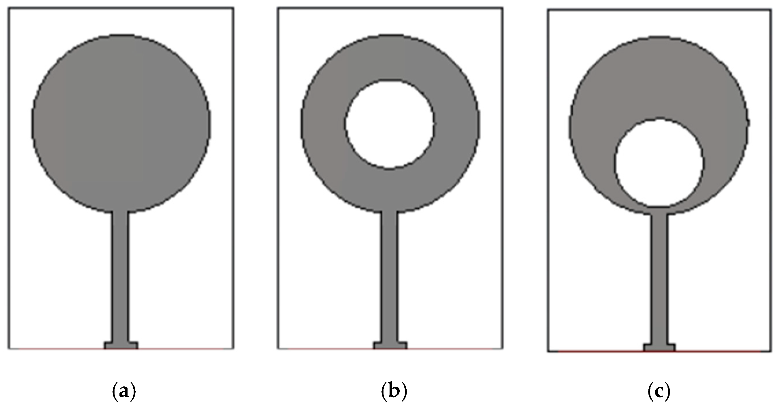
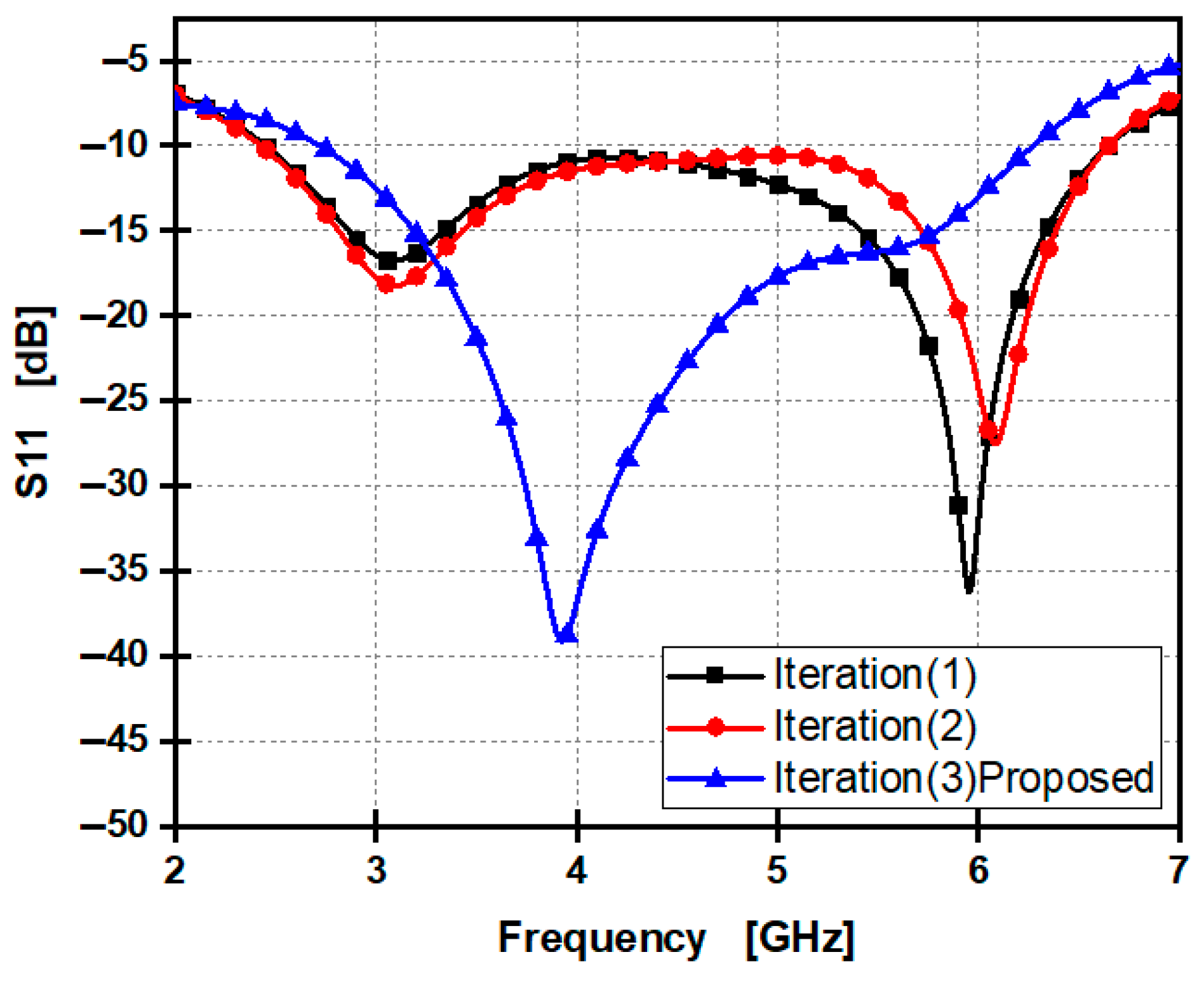
2. Evolution of Single Antenna Element

The proposed circular antenna is designed using CST Microwave Studio software 2018, and fabricated based on RT5880. In this section, design simulation, fabrication results and comparison with previous works, achieving optimal signal integrity, high gain, and out-standing performance.

2.1. Antenna Design

In CST Microwave Studio, we expertly designed a circular patch antenna specifically tailored for the 5G sub-6 GHz spectrum at a central frequency of 4 GHz. To achieve optimal signal integrity and minimize losses for reliable performance, we selected an RT5880 substrate with an overall size of 30 × 46 × 1.57 mm3. This remarkable material offers a dielectric constant of 2.2, an exceptionally low loss tangent of 0.0009, and a thickness of 1.57 mm, making it an excellent choice for electrical and mechanical applications. ROGER’s superior electrical characteristics in RF and microwave circuits significantly diminish signal loss and distortion, which are critical components for cutting-edge communication systems, radar technologies, and high-frequency electronics. Its stable dielectric properties across a wide frequency range make it an ideal candidate for vital industries such as aerospace and telecommunications.
The patch and ground layers are constructed from copper, measuring 0.035 mm thickness. The patch is excited using a Microstrip line feeding technique, and to ensure broadband operation, we have included a partial ground plane on the substrate’s rear side. The initial task is to compute the radius (r) of the circular patch with Equations (1) and (2) [29], setting the groundwork for effective performance.
r = F 1 + 2 h π F ε r ln π F 2 h + 1.7726
F = 8.791 × 10 9 f r ε r
The parameters h , ε r and f r represent the configuration’s thickness, relative permittivity, and resonance frequency. Table 1 provides the actual design dimensions.
To ensure a compact structure while ensuring the desired operational bandwidth, we strategically minimized the patch’s dimensions by adjusting the partial ground plane length. Our design utilizes a defective circular stub patch antenna. To enhance the antenna’s reflection coefficient (S11), we also expanded the antenna’s bandwidth and increased the aperture area by adding a circular slot at the lower section of the patch.
Figure 1 presents the simulated design and fabricated prototype antenna. This well-considered design not only fulfils performance requirements but also excels in efficiency and effectiveness. The design’s input impedance is around 50 ohms at the central frequency, as shown in Figure 1e.

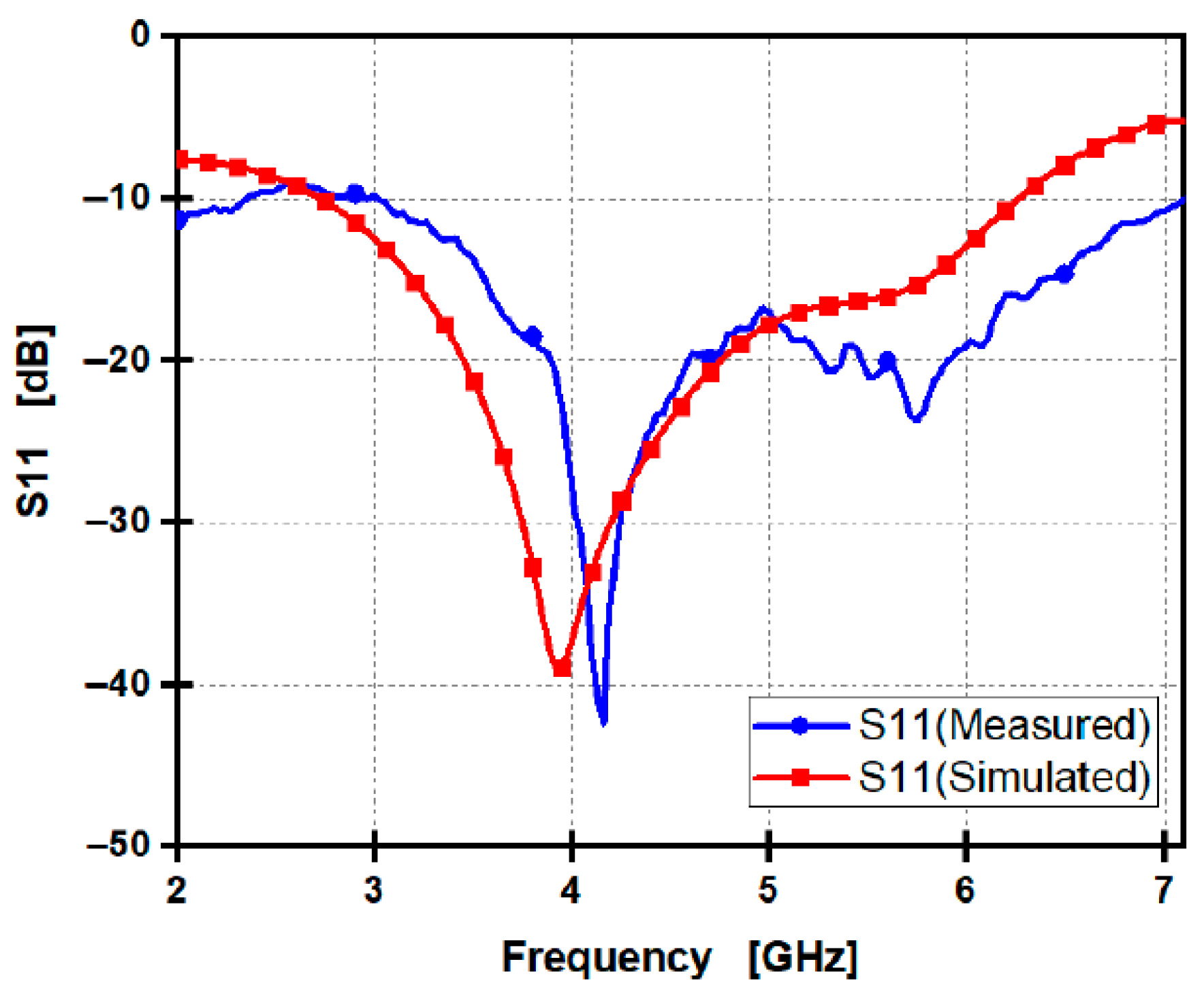
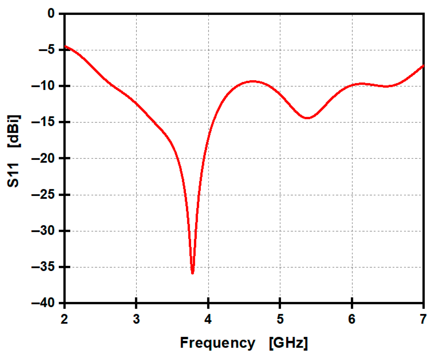
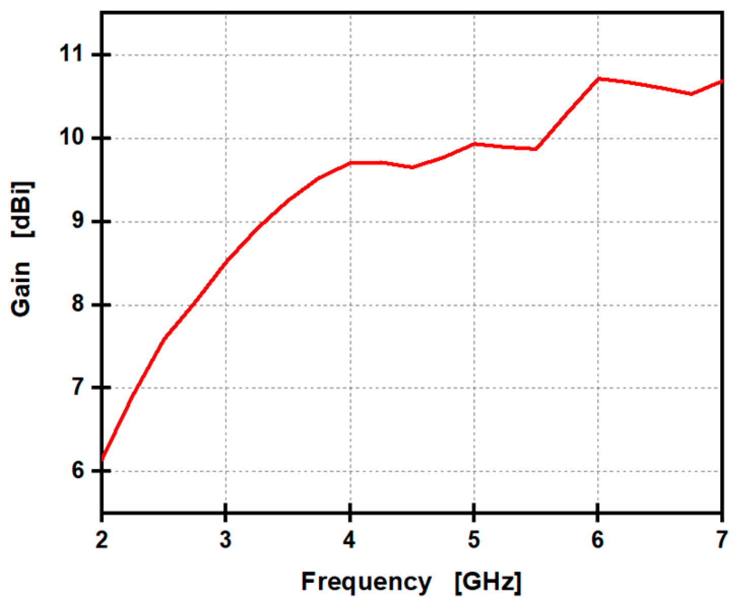
2.2. Performance and Discussion

Figure 2 illustrates the single proposed circular antenna design’s reflection coefficient (S11). The simulation shows that the S11 remains lower than −10 dB across the frequency range of 2.73 GHz to 6.3 GHz, where the minimum simulated S11 is −38 dB. In contrast, the measured S11 for the antenna is lower than −10 dB at (2.96:7.1 GHz), but achieves a lower minimum measured S11 of −42 dB. This indicates that the fabricated antenna effectively covers all required frequency bands while maintaining good matching and high performance compared to the designed antenna.
Figure 3 illustrates the changes in gain across the frequency band. The simulated gain starts from 2.1 dBi at 2 GHz and increases gradually, reaching 4.45 dBi at 6.15 GHz as a peak gain. At frequencies of 3.5 GHz and 5.8 GHz, the circular-shaped antenna exhibits simulated gains of 2.7 dBi and 4.3 dBi, respectively. The measured gain starts from 1.7 dBi at 2 GHz and increases gradually, reaching 4.3 dBi at 6.15 GHz as a peak gain. At frequencies of 3.5 GHz and 5.8 GHz, the circular-shaped antenna exhibits measured gains of 2.49 dBi and 3.7 dBi, respectively.
The radiation pattern of the fabricated antenna was assessed in an anechoic chamber, as illustrated in Figure 4c. Figure 4a,b present a radiation pattern of both simulated and measured electric fields at frequencies of 3.5 GHz and 5.8 GHz, respectively. At 3.5 GHz, the main lobe gain is 2.84 dBi, indicating good radiation intensity. The main lobe is directed at 194°. The angular width measures 92.2°, suggesting a broad main beam. At 5.8 GHz, the main lobe gain increases to 4.23 dBi, indicating strong radiated power. The main lobe is directed at 161°. The angular width is 69.3°, providing a balanced trade-off between directionality and coverage. Simulated and measured radiation patterns nearly resemble each other. The observed slightly asymmetric radiation between back radiation and broadside radiation is attributed to a partial ground, which plays a crucial role in enhancing bandwidth in our antenna design. When a microstrip antenna is constructed on a substrate with a partially grounded plane, surface waves travel along the ground plane until they reach the edges of the antenna. At those edges, the reflection and diffraction of waves lead to somewhat increased back radiation patterns in comparison to broadside radiation.

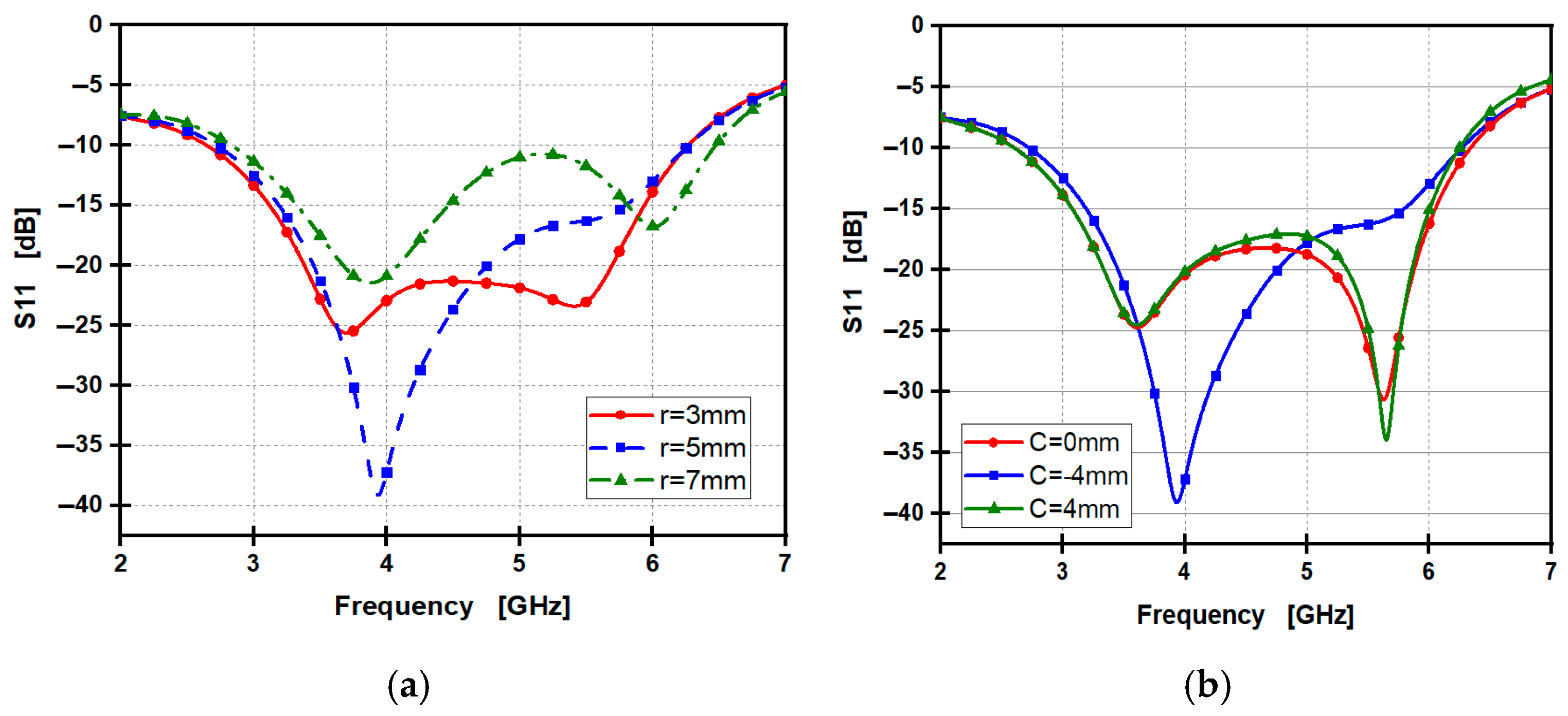
2.3. Performance Analysis

The functionality of a defective circular-shaped antenna is evaluated by comparing its performance at each iteration after making changes. All design iterations maintain a partial ground on the backside. Figure 5 illustrates the adjustments to the top geometry. Figure 5a shows the traditional solid circular patch structure of the proposed antenna. The second iteration, represented in Figure 5b, includes a slot in a circular shape that is introduced at the center of the patch. In the third iteration, depicted in Figure 5c, the slot is shifted downward by 4 mm from the center.
Figure 6 highlights the effects of these changes on the S11 for the three iterations. The S11 curve progression demonstrates that the single antenna design achieves optimal performance, maintaining simulated S11 values below −10 dB across a frequency range from 2.73 GHz to 6.3 GHz. This high gain is notably achieved with the circular slot antenna design featuring the shifted slot at −4 mm.
The S11 values for the first and second iterations—representing the solid patch and the central slot, respectively—show that S11 approaches the −10 dB threshold between 4 GHz and 5.2 GHz. In contrast, the third iteration with the lower shifted slot exhibits improved stability, reaching values as low as −40 dB and providing excellent coverage at the operational frequency band.
The effectiveness of the proposed antenna is influenced by various factors, and a parametric analysis has been performed to fine-tune its design.
The position of the slot on the patch is vital for energy coupling, current distribution, and radiation efficiency. When the slot is near the feed line, it is closer to the high current region, allowing more energy to couple directly into the slot. This enhances interaction with the input excitation and directs current toward the patch edges, resulting in stronger radiation and better S11 performance with lower reflection. In contrast, a centered slot is farther from the feed, reducing coupling efficiency and potentially distorting mode symmetry, which can lead to unwanted mode excitation.
In Figure 7a, the antenna features a central circular slot, which creates a highly symmetrical current distribution around both the slot and the patch. However, the current intensity is low and diffused, particularly around the edges of the slot, leading to weak coupling, low radiation efficiency, and potentially narrow bandwidth. In Figure 7b, the circular slot is shifted downward, bringing it closer to the feed point. This adjustment leads to stronger current localization, especially around the lower section of the patch near the slot. As a result, there is better excitation, stronger resonance, and higher efficiency compared to the central-slot design. The enhanced current strength in critical areas makes the patch with a shifted down slot the superior design, particularly for improving gain or bandwidth S11.
In Figure 8a, the impact of the radius of the circular centered slot (r) on the antenna’s impedance matching and its reflection coefficient response (S11) is depicted. Adjusting the slot radius from 3 mm to 7 mm enhances both impedance matching and stability. The optimal radius is 5 mm, which achieves an S11 of −40 dB, while a radius of 3 mm results in an S11 of −25 dB. In contrast, a radius of 7 mm yields an S11 of −21 dB, and at 5 GHz, S11 is close to −10 dB. Figure 8b illustrates how the S11 curve is influenced by shifting the slot’s center about 4 mm upward and −4 mm downward from the patch’s exact center. This shift in the slot’s center improves the impedance match, resulting in a more stable response below −10 dB, providing a simulated wide frequency band from 2.73 GHz to 6.3 GHz. The antenna design with the circular slot, shifted −4 mm downward from the center of the patch, exhibits a wider frequency bandwidth and enhanced impedance matching characteristics.

2.4. Performance Comparison of the Single Antenna with Previous Works

The comparison in Table 2 highlights the circular-shaped design’s performance against existing 5G antennas at sub-6 GHz. The suggested antenna exhibits higher gain and a broader operational frequency range compared to the maximum bandwidth and gain of previously published antennas [30,31,32]. Although antenna [31] is relatively compact in size, the proposed design has a greater gain and wider bandwidth than it.
The proposed single element design improves max percentage gain compared with previously described designs [30,31,32] by 72%, 202%, and 86%, respectively.

3. A 2-Port MIMO System Using Two Flipped Parallel 1 × 2 Arrays Antenna

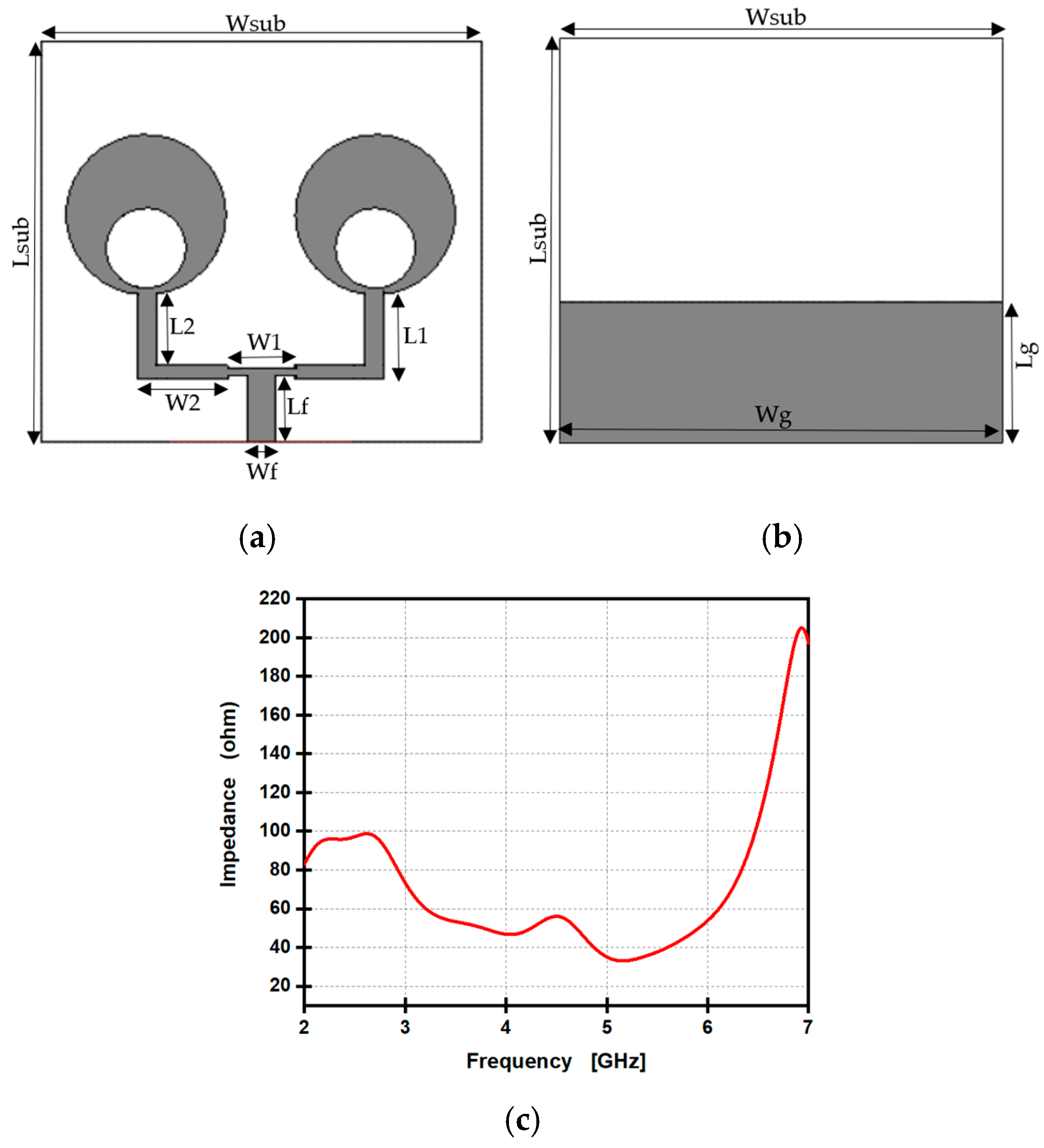
3.1. Design of (1 × 2) Antenna Array Arrangement

Higher antenna gain is necessary due to the longer operating wavelengths in sub-6 GHz compared to higher frequency bands like mm-wave and terahertz. Antenna gain significantly affects coverage and signal strength performance. To enhance gain, a two-element circular-shaped antenna array has been designed. The two-element array can potentially double the gain in dB compared to a single antenna. A common feeding line is utilized to power the radiating elements. Figure 9a,b illustrate the geometric top and back views of the antenna. The design’s input impedance is around 50 ohms at 3.5 GHz and 5.8 GHz, as shown in Figure 9c.
The design is composed of a 1 × 2 array based on defective circular patches linked by a transformer using a power splitter. Table 3 provides the actual design’s dimensions, which has an overall size of 66 × 60 × 1.57 mm3.
The simulated S11 of the suggested 1 × 2 array of circular antennas is exhibited in Figure 10. The simulated design supports a frequency band of 2.59–6.1 GHz. The S11 is less than −10 dB over the whole operational range. The minimal value measured for S11 is −33 dB at 4 GHz. Figure 11 illustrates the changes in gain across the frequency band. The simulated gain starts from 3.1 dBi at 2 GHz and, increasing gradually, reaches 8.16 dBi at 6.4 GHz as a peak gain. Within the frequency band from 3 GHz to 6 GHz, the gain grows from 4.2 dBi to 8 dBi. At frequencies of 3.5 GHz and 5.8 GHz, the circular-shaped antenna exhibits gain of 5 dBi and 8.5 dBi, respectively.
Figure 12 shows a radiation pattern of simulated electric fields at the sub-6 GHz band. Figure 12a shows that, at frequency 3.5 GHz, the antenna has a figure-eight radiation pattern, indicating that it radiates strongly in two opposite directions. Its main lobe gain is 4.73 dBi, directed at 184°. The 3 dB beamwidth is 84.4°, which means the antenna has a relatively wide beam. Figure 12b shows that, at frequency 5.8 GHz, the main lobe magnitude is 8 dBi at 175°, which is almost directly along the broadside direction (180°). This indicates symmetric radiation and good alignment. The main lobe gain is quite high, with strong directionality and efficient radiation. The 3 dB beamwidth, measures 62.5°, which is narrower than the beamwidth at 3.5 GHz (84.4°). This means that the radiation is more precise and directive at 5.8 GHz.

3.2. Design of a 2-Port MIMO System Using Two Flipped Parallel 1 × 2 Arrays Arrangement

Modern communication systems necessitate the use of MIMO antennas to enhance network capacity. A two-element MIMO combined from two flipped (1 × 2) arrays is designed, simulated, and fabricated. Spatial diversity of antennas sufficiently controls MIMO efficiency to increase channel capacity. The design of the MIMO array antenna incorporates redundant operations with high gain, leading to improved error rates and enhanced efficiency in wireless systems. To create a 2-port MIMO system using two flipped parallel 1 × 2 arrays, two antenna elements are initially placed at a distance of half a wavelength apart. A 0.1 mm-thin copper grounding line connects the two opposing 1 × 2 arrays. This grounded connection helps reduce mutual coupling between the patches. Figure 13 displays both the simulated design and the fabricated prototype of the design. Figure 13e illustrates that the maximum radiation efficiency reaches 95% at 3.5 GHz and 94.7% at 5.8 GHz. Table 4 provides the actual design dimensions, which have an overall size of 132 × 66 × 1.57 mm3.

3.3. Measurement Results Discussion of Two 1 × 2 Arrays MIMO

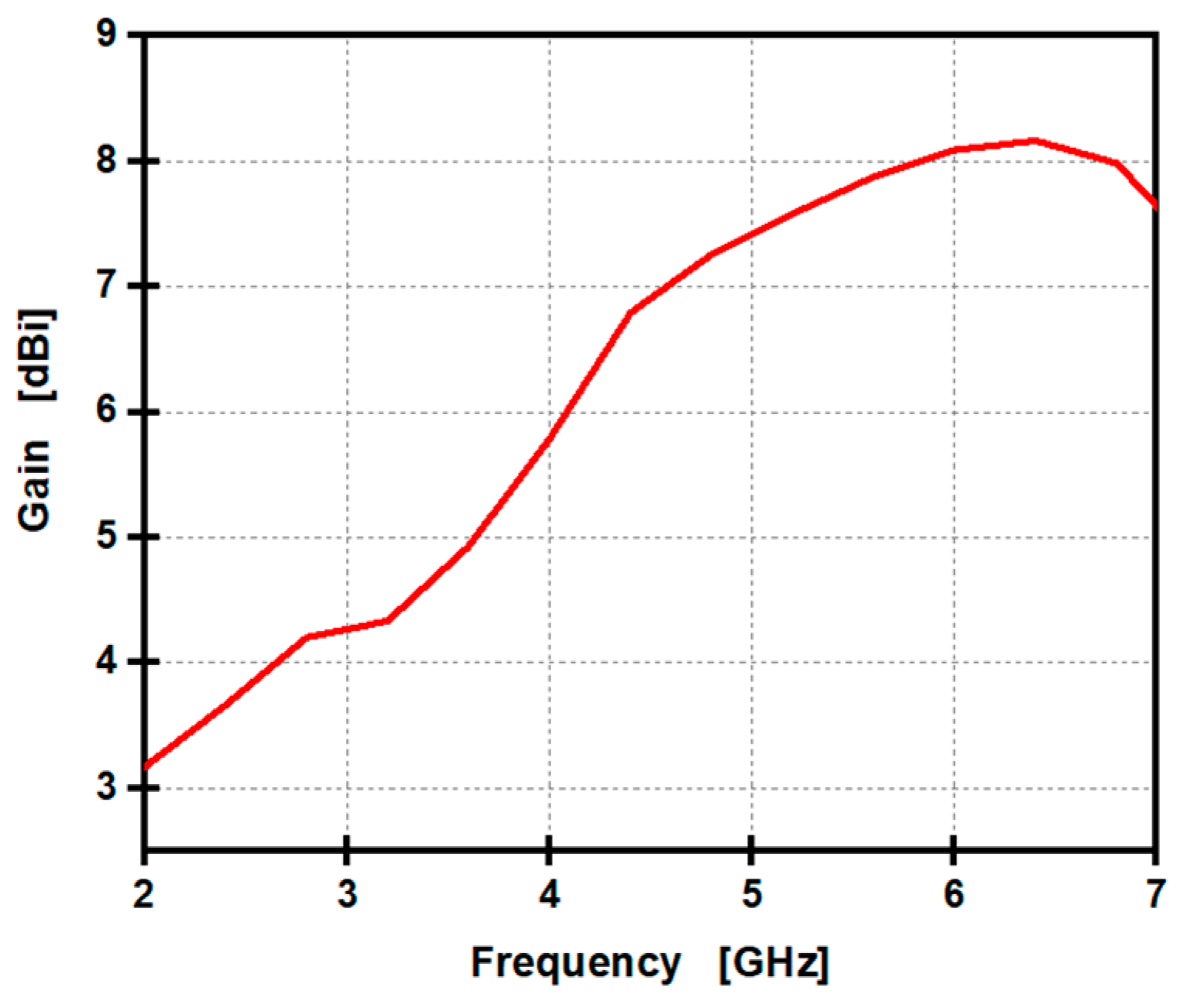
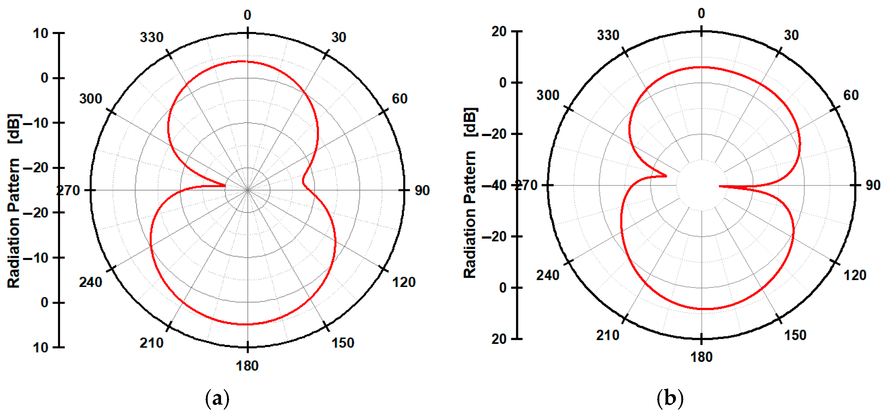
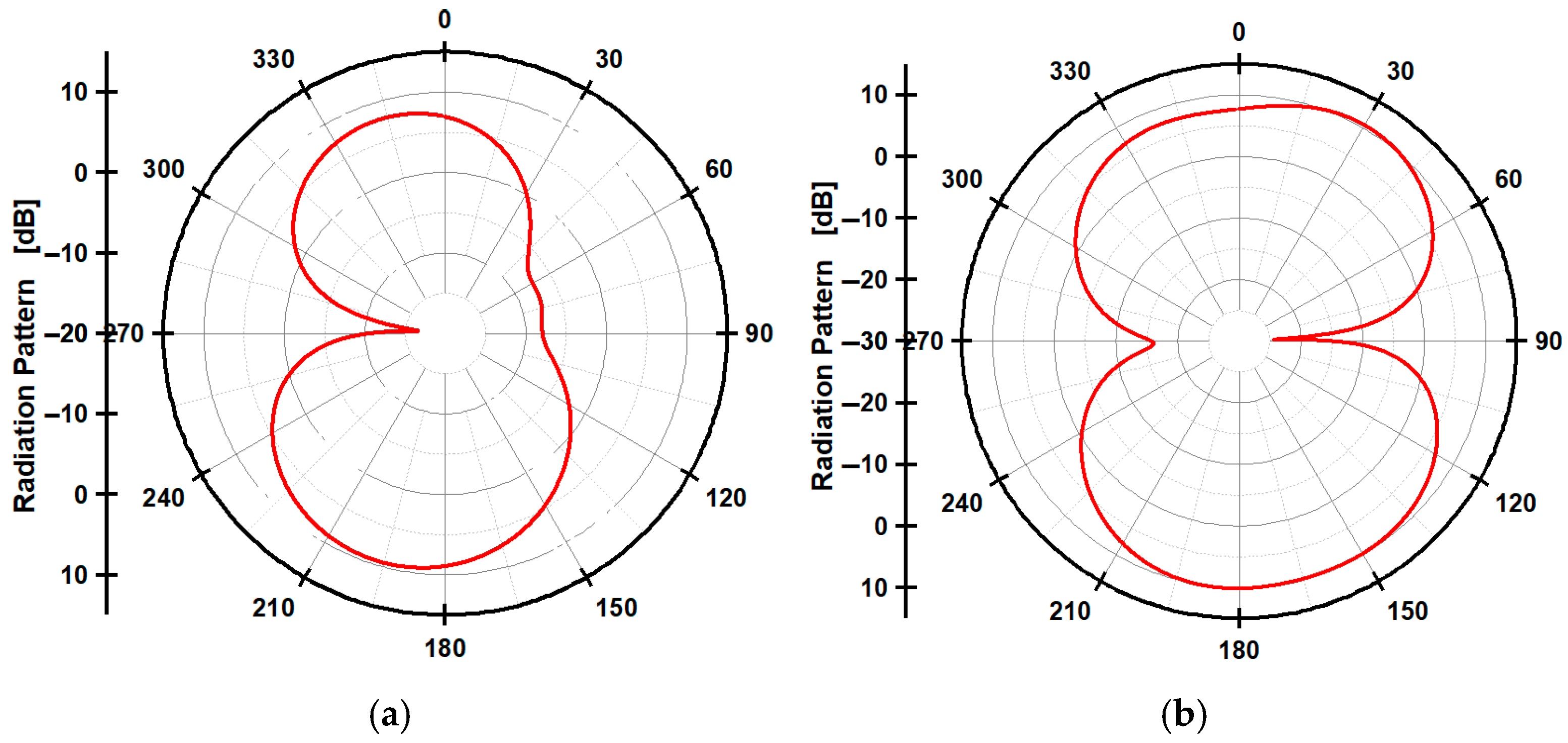
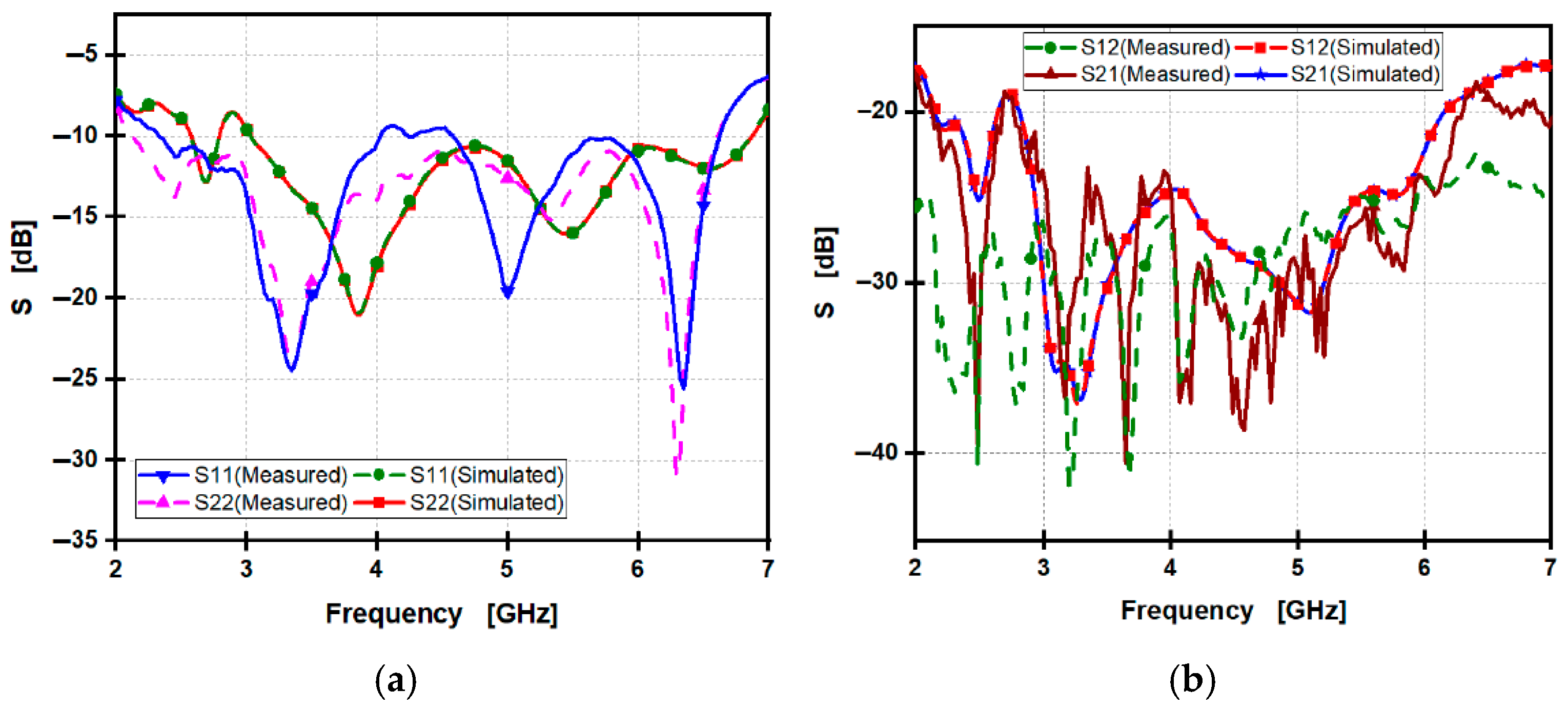
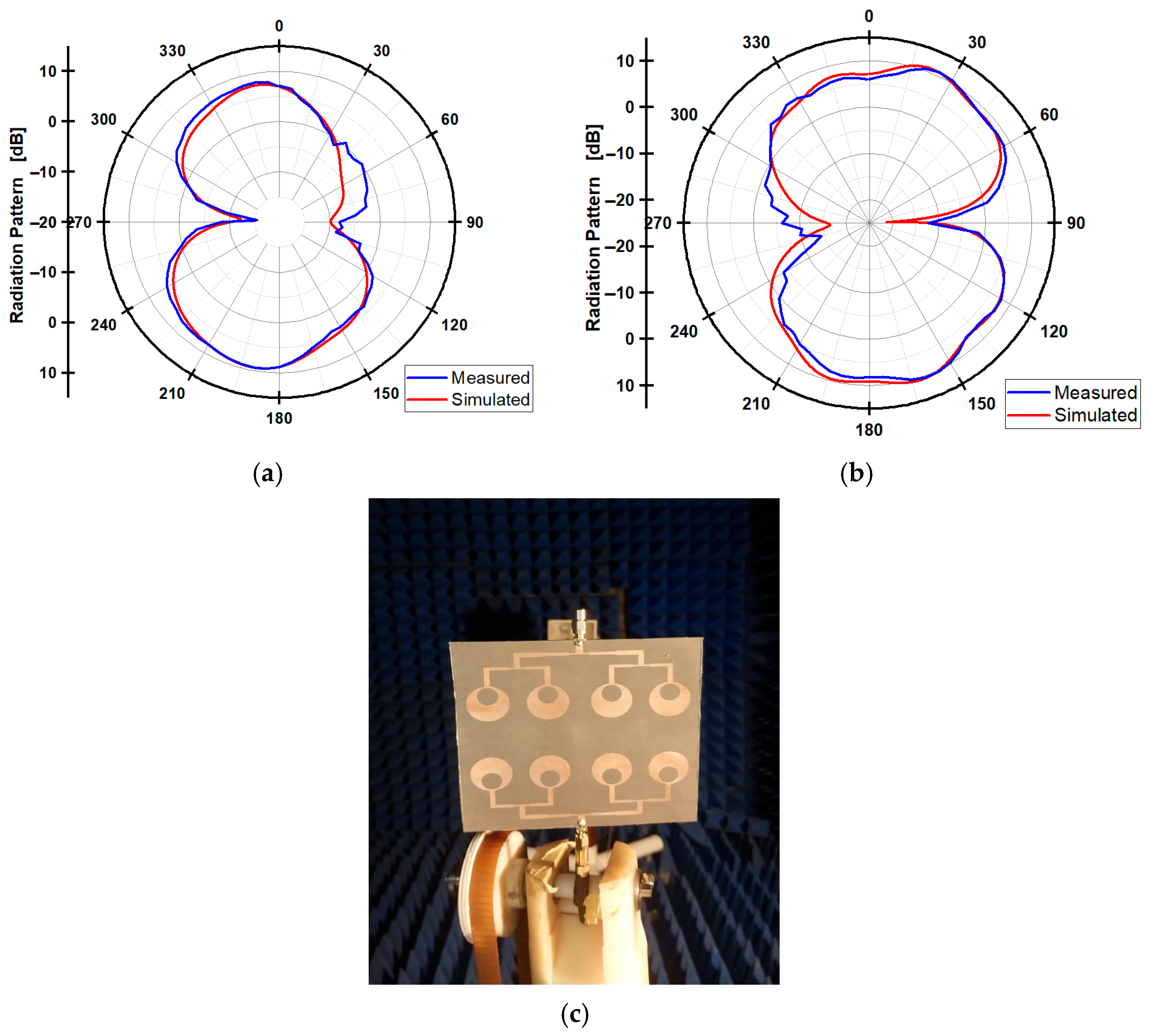
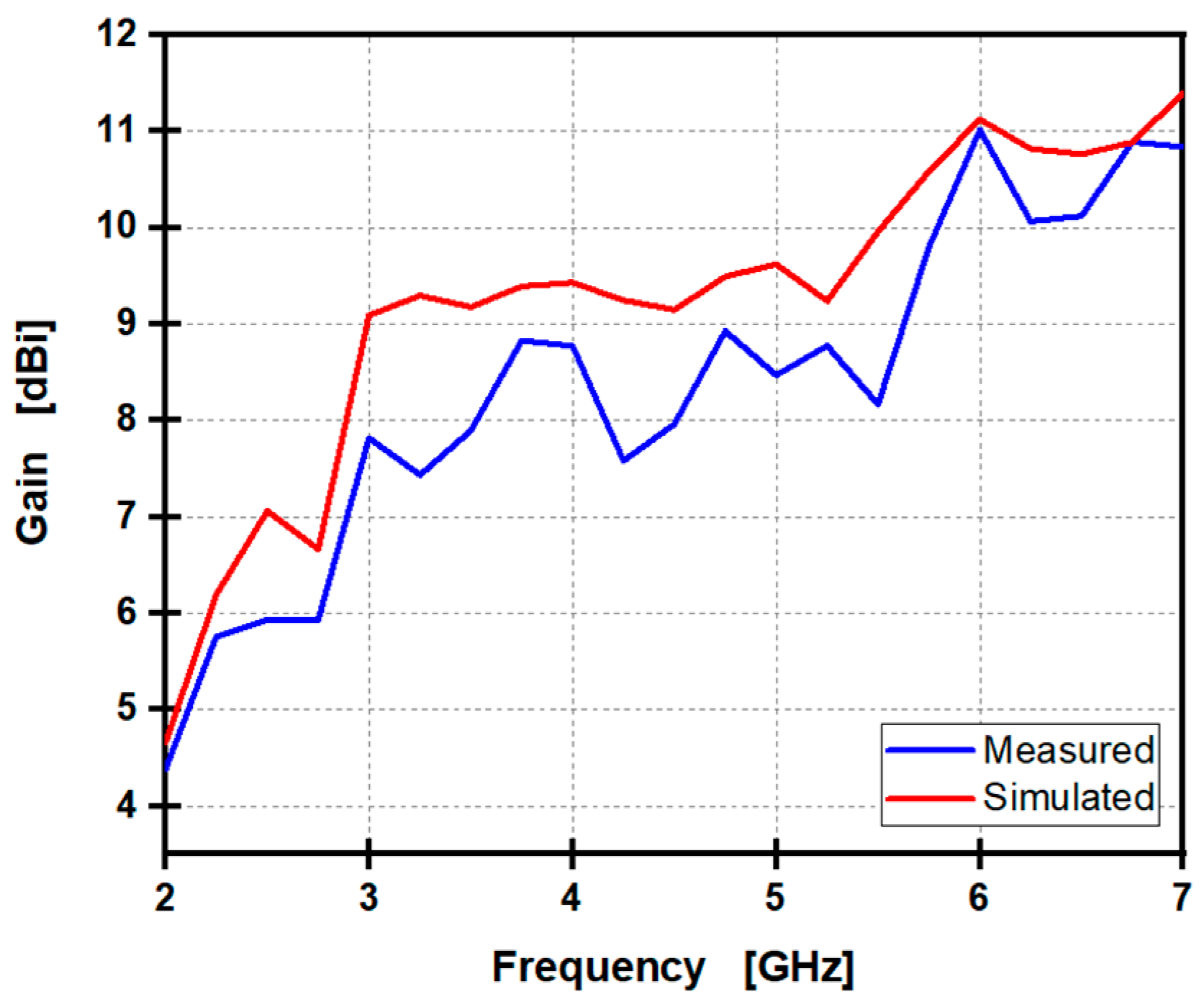
3.3.1. Reflection, Transmission Coefficients, Radiation Pattern, and Gain Results

Figure 14a illustrates the simulated and measured reflection coefficients (S11 and S22) of the proposed MIMO of two 1 × 2 antenna arrays design. The measurement shows that the reflection coefficient S11 remains below −10 dB across a band of (2.27:4.94 GHz) and (5.53:7.84 GHz), where the minimum simulated S22 is −44 dB, and the measured S11 appears very similar to the measured S22. In contrast, it shows that the simulated S11 for the antenna is below −10 dB from 2.1 GHz to 2.7 GHz and 3.05 GHz to 6.23 GHz, but achieves a lower minimum measured S11 of −31 dB, where the simulated S11 appears very similar to simulated S22. This indicates that the fabricated antenna effectively covers all required frequency bands while maintaining good matching and high performance compared to the designed antenna. Figure 14b illustrates the measured and the simulated S12 and S21. The measured data show that the S12 is ˂−20 dB over the band of (3:7 GHz), where the measured S12 appears very similar to the measured S21. In contrast, it shows that the simulated S12 for the antenna is below −20 dB from 3 GHz to 6.8 GHz, where the simulated S11 appears very similar to the simulated S21. This indicates that the fabricated antenna has high performance.
Figure 15 shows a radiation pattern of both simulated and measured electric fields at the sub-6 GHz band. Figure 15a,b present a radiation pattern of both simulated and measured electric fields at frequencies of 3.5 and 5.8 GHz, respectively. At 3.5 GHz, the main lobe magnitude is 4.83 dBi. The high front-to-back ratio (the difference in gain between the main lobe and side lobes) indicates excellent directivity. The main lobe is centered around 183°, which is almost perfectly aligned along the broadside. The 3 dB beamwidth is 94.1°, which is relatively wide. At 5.8 GHz, the radiation pattern shows a main lobe with a peak gain of 8.33 dBi directed at 167°, indicating slightly off-broadside radiation. The main lobe is quite strong, demonstrating good directivity. The angular width of 50.4° suggests a moderate beam spread that balances coverage and directivity.
Figure 16 illustrates the changes in gain across the frequency band. The simulated gain starts from 3.2 dBi at 2 GHz and increases gradually, reaching 8.9 dBi at 6.8 GHz as a peak gain. At frequencies of 3.5 GHz and 5.8 GHz, the circular-shaped antenna exhibits gain of 5 dBi and 8.5 dBi, respectively. The measured gain starts from 1.7 dBi at 2 GHz and increases gradually, reaching 8.3 dBi at 6 GHz as a peak gain. At frequencies of 3.5 GHz and 5.8 GHz, the circular-shaped antenna exhibits gain of 4.45 dBi, and 8.3 dBi, respectively.

3.3.2. MIMO Performance Results of Two 1 × 2 Arrays MIMO

The reliance on MIMO antenna configurations in modern wireless communication systems is enhancing overall system performance. To ensure optimal MIMO functionality, it is essential to achieve isolation, which mitigates the need for an external decoupling network. Additionally, several key factors influencing MIMO performance, such as the CCL, ECC, DG, TARC, and MEG [33,34,35]. Figure 17 presents the calculation results of a MIMO of two 1 × 2 antenna arrays.
The CCL represents the minimum practical losses experienced by a MIMO system, and for it to be considered an acceptable standard, it is preferred to be below 0.4-bit/s/Hz. CCL can be estimated using Equations (3)–(8). Figure 17a illustrates a comparison of CCL values from both measured data and simulations, showing that they remain under 0.4-bit/s/Hz, particularly at the resonant frequency band.
CCL = l o g 2 det a .
a =   ξ 11 ξ 12 ξ 21 ξ 22 ,
ξ 11 = 1 S 11 2 + S 12 2 ,
ξ 12 = S 11 S 12 + S 21 S 12 ,
ξ 21 = S 22 S 21 + S 12 S 21 ,
ξ 22 = 1 S 22 2 + S 21 2 ,
The ECC parameter quantifies the changes in the diversity factor, indicating the relationship between antennas within a MIMO system. It can be determined using S-parameters, as in Equation (9). Figure 17b illustrates a comparison of simulation results and measurements, revealing that both are closely similar. ECC approach zero between 2.9 GHz and 5.1 GHz, with values of 0.006 dB at 2.8 GHz and 0.0025 dB at 5.2 GHz, which is considered an effective antenna as it trends towards zero.
ρ e i j = S 11 S 12 + S 21 S 22 2 ( 1 S 11 2 S 21 2 ) ( ( 1 S 22 2 S 12 2 ) .
The DG serves as a metric for assessing the quality and reliability of a MIMO antenna. It is derived from the envelope correlation coefficient (ECC), as in Equation (10), and is considered favorable when it approaches 10 dB across the operating frequency range. In comparing simulation results with actual measurements, Figure 17c indicates that both yield a diversity gain of 10 dB that contributes to an efficient antenna design.
DG = 10   1 ρ e i j 2   .
The TARC is defined as the square root of the ratio between the total power that is reflected and the power that is incident. TARC can be calculated from Equation (11). For effective antenna design, TARC values should be below −10 dB. As illustrated in Figure 17d, the TARC remains below −10 dB, especially at the resonant frequency.
T A R C = ( S 11 + S 12 e j ɵ ) 2 + ( S 21 + S 22 e j ɵ ) 2 2 .
The MEG is considered the total adequate average power received over the total average power received by an isotropic antenna. MEG can be calculated from Equation (12). For MIMO systems to meet acceptable performance standards, MEG should be between zero and −3 dB. MEG1 and MEG2 values close to −6 dB that because to bidirectional radiation. The comparison between the simulation results is shown in Figure 17e.
M E G i = 1 j = 1 M S i j 2 .
It has been observed that TARC in Figure 17d exhibits higher variability between simulation and measurement compared to other parameters. This is because TARC is highly sensitive to phase changes. In contrast, ECC, MEG, DG, and CCL are mathematically derived from stable quantities of S-parameters. These parameters utilize averaging techniques or statistical models that do not require precise phase control or active excitation. Despite this variability, both the simulated and measured TARC values remain below −10 dB, particularly at the desired frequencies, indicating an effective design.

3.4. Performance Comparison of Two 1 × 2 Arrays MIMO with Previous Works

The comparison in Table 5 highlights the performance of the proposed MIMO of two 1 × 2 arrays against existing sub-6 GHz 5G antennas. The suggested antenna exhibits higher gain, radiation efficiency, and a wider operational frequency range compared to the previously published antennas [36,37,38]. Although the antennas in ref. [27,39] are relatively smaller in size compared with the proposed antenna, the proposed antenna achieves a greater gain and wider operational bandwidth than it. Additionally, the proposed design presents the smallest value of ECC, which means the best MIMO performance. The proposed MIMO of two 1 × 2 arrays design improves max percentage gain compared with previous designs [27,38,39] by 26.5%, 43.1%, and 277%, respectively, achieving maximum radiation efficiency of up to 95%.

4. A 2-Port MIMO System Using Two Opposite 1 × 4 Antenna Arrays

In this section, a 1 × 4 array based on a single circular patch to maximize the offered gain, reaching 10.9 dBi at the frequency band from 3 dB to 6 dB, is designed and fabricated.

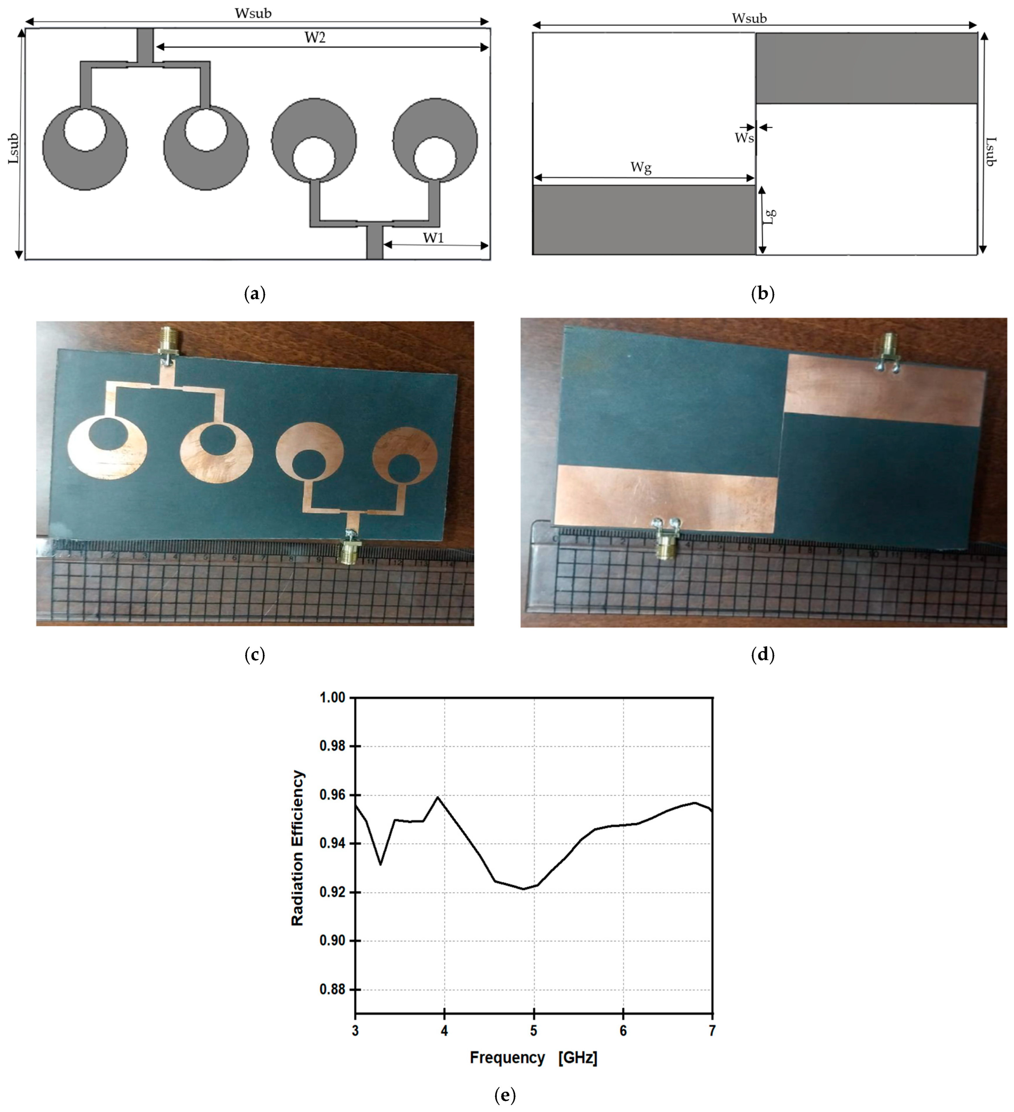
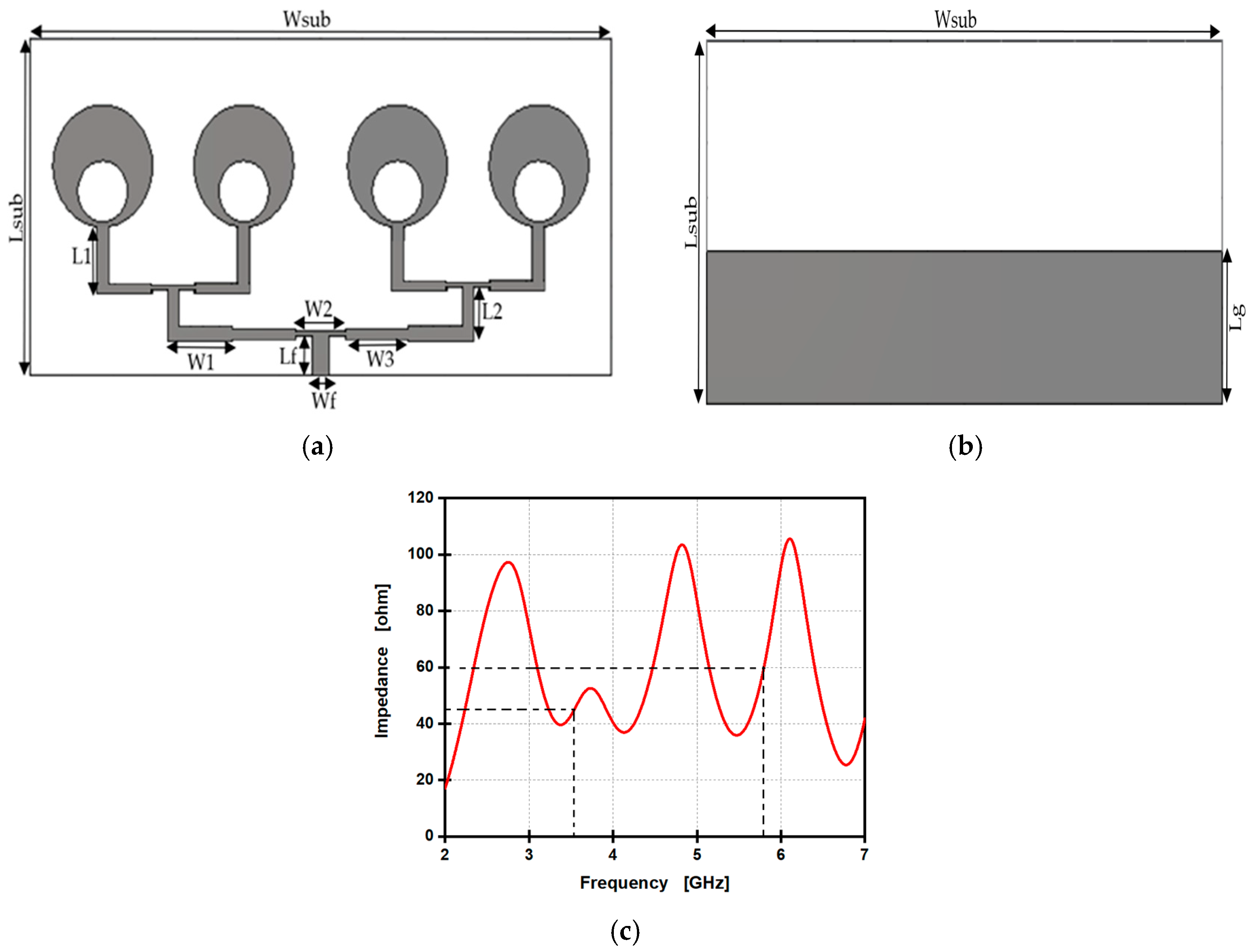
4.1. Design of (1 × 4) Antenna Array Arrangement

Maximizing antenna gain for improved coverage and connection performance in 5G applications, particularly in the sub-6 GHz range can achieve an increase in gain of approximately three times in dBi, when comparing a 1 × 4 array antenna configuration to a single element or a 1 × 2 array. The simulated top and back sides of the design are illustrated in Figure 18. The design’s input impedance is around 50 ohms at 3.5 GHz and 5.8 GHz, as shown in Figure 18c. Table 6 lists the design dimensions.
The simulated reflection coefficient (S11) of the suggested 1 × 4 array of circular antennas is shown in Figure 19. The antenna resonates at dual bands: 2.68 GHz to 4.4 GHz and 4.85 GHz to 5.69 GHz. The minimal value measured reflection coefficient (S11) is −36 dB. Figure 20 illustrates the changes in gain across the frequency band. The simulated gain starts from 6.1 dBi at 2 GHz and increases gradually, reaching 10.8 dBi at 6 GHz as a peak gain. During the frequency band from 3 GHz to 6 GHz, the gain grows from 8.5 to 10.7 dBi. At frequencies of 3.5 GHz and 5.8 GHz, the circular-shaped antenna exhibits gain of 9.2 and 10.6 dBi, respectively.
The radiation pattern of the simulated antenna is established for the E-plane radiation pattern at 3.5 GHz and 5.8 GHz, as demonstrated in Figure 21. Figure 21a shows that, at a frequency of 3.5 GHz, the main lobe peaks at 9.25 dBi, demonstrating high directivity with a beam pointing at 196°. The 3 dB beamwidth is 71.6°, offering a balance between directionality and coverage. The lack of prominent side lobes indicates effective sidelobe suppression, reducing interference. Figure 21b shows that, at frequency 5.8 GHz, the main lobe reaches a peak gain of 10.4 dBi, showing strong directivity with the main beam centered at 30°. The 3 dB beamwidth of 58.7° reflects a focused beam with good spatial resolution. The well-formed radiation pattern features minimal side lobes, resulting in low interference and high efficiency.

4.2. Design of 2-Port MIMO System Using Two Opposite 1 × 4 Arrays Arrangement

Boosting network capacity, bandwidth, and increasing gain maximization benefits, a MIMO of two 1 × 4 arrays design is simulated and fabricated. The proposed design is arranged as two flipped 1 × 4 array elements positioned at a half wavelength distance with a flipped opposite array direction, constructing a MIMO of two 1 × 4 arrays. A 1 mm-thin copper grounding squiggly defective square line connects the two flipped opposite 1 × 4 arrays. This grounded connection increases the electrical length and inductance, which influences the flow of surface currents on the ground plane. As a result, it reduces wave propagation in unwanted directions and helps block mutual coupling currents, particularly around resonance. This method can be effective in suppressing surface wave propagation between antenna elements. Figure 22 displays both the simulated design and the fabricated prototype of the MIMO of two 1 × 4 arrays. Figure 22e illustrates that the maximum radiation efficiency reaches 97.46% at 5.8 GHz and 95.16% at 3.5 GHz. Table 7 provides the actual design dimensions, which have an overall size of 140 × 132 × 1.57 mm3.

4.3. Measurement Results Discussion of Two 1 × 4 Arrays MIMO

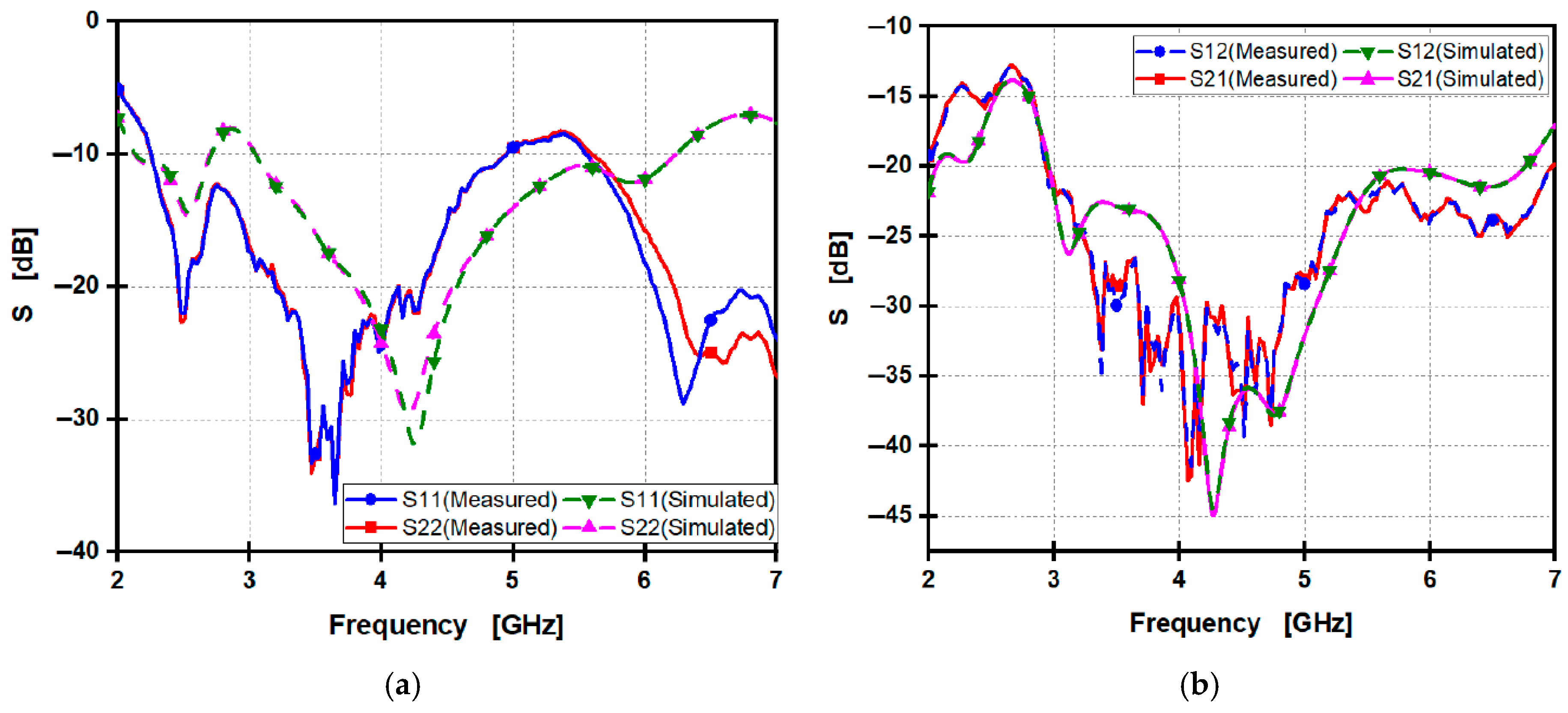
4.3.1. Reflection, Transmission Coefficients, Radiation Pattern, and Gain Results

Figure 23a illustrates the simulated and measured reflection coefficients (S11 and S22) of the proposed MIMO of a two 1 × 4 arrays design. The measurement shows that S11 remains below −10 dB over the frequency ranges of 2.33:4.02 GHz, 4.25:4.4 GHz, and 4.6:6.62 GHz, where the minimum measured S11 is −25 dB, and the measured S11 appears quite equal to the measured S22. In contrast, it shows that the simulated S11 for the antenna is below −10 dB at 2.57:2.79 GHz and 3.03:6.86 GHz, but achieves a lower minimum simulated S11 of −22 dB. The simulated S11 appears quite equal to the simulated S22.
This indicates that the fabricated antenna effectively covers all required frequency bands while maintaining good matching and high-performance antenna. Figure 23b illustrates the simulated and measured reflection coefficient (S12 and S21), showing that the reflection coefficient S12 and S21 remain below −20 dB over the frequency range, especially at resonance frequencies, indicating that the fabricated antenna has a high performance.
Figure 24a,b present a radiation pattern of both simulated and measured electric fields at frequencies of 3.5 and 5.8 GHz, respectively. At 3.5 GHz, the peak gain increases to 9.18 dBi, showing strong directivity. The beam is directed at 191° with a beamwidth of 63.5°. At 5.8 GHz, the peak gain reaches 10.8 dBi at 22°, reflecting strong directional radiation. There is a narrower beamwidth of 52.7°.
Figure 25 illustrates the changes in gain across the frequency band. The simulated gain starts from 4.6 dBi at 2 GHz and increases gradually, reaching 11 dBi at 6 GHz as a peak gain. At frequencies of 3.5 GHz and 5.8 GHz, the design exhibits gain of 9.1, 10.9 dBi, respectively. The measured gain starts from 4.5 dBi at 2 GHz and increases gradually, reaching 10.9 dBi at 6 GHz as a peak gain. At frequencies of 3.5 GHz and 5.8 GHz, the design exhibits gains of 8 and 10.9 dBi, respectively.

4.3.2. MIMO Performance Results of Two 1 × 4 Arrays MIMO

Figure 26 presents the comparison between measured and simulated calculation results of a MIMO of two 1 × 4 arrays antenna using Equations (3)–(12) as in Section 3.3.2. CCL can be estimated using Equations (3)–(8). CCL should be less than 0.4-bit/s/Hz to be considered an effective performance. Figure 26a illustrates a comparison of CCL values from both measured data and simulations, showing that they remain under 0.3-bit/s/Hz, particularly at the resonant frequencies.
ECC can be calculated as a function of S-parameters, as in Equation (9). Its value tends to zero, leading to an effective performance. Figure 26b illustrates that the ECC is less than 0.003, particularly at the resonant frequencies.
DG is calculated from ECC, as in Equation (10), and a value tending to 10 dB leads to an effective performance. Figure 26c indicates that DGs for both measured and simulated values yield a diversity gain of 10 dB, which contributes to an effective antenna design.
TARC is the reflected total power to the incident power. TARC can be calculated from Equation (11). A value less than −10 dB leads to an effective performance. Figure 26d indicates that TARC remains below −10 dB, especially at the resonant frequencies.
MEG considers the received average power compared to the received average power by an isotropic antenna. MEG can be calculated from Equation (12). MEG1 and MEG2 values close to −6 dB result because of bidirectional radiation. The MEG comparison between measured and simulation results is shown in Figure 26e.
It can be observed that TARC in Figure 26d exhibits higher variability between simulation and measurement compared to other parameters. This is because TARC is highly sensitive to phase changes. In contrast, ECC, MEG, DG, and CCL are mathematically derived from stable quantities of S-parameters. These parameters utilize averaging techniques or statistical models that do not require precise phase control or active excitation. Despite this variability, both the simulated and measured TARC values remain below −10 dB, particularly at the desired frequencies, indicating an effective design.

4.4. Performance Comparison of Two 1 × 4 Arrays MIMO with Previous Works

The comparison in Table 8 highlights the performance of the proposed MIMO two 1 × 4 arrays design against existing sub-6 GHz 5G antennas. The suggested antenna exhibits higher gain and a wider operational frequency range compared to the maximum bandwidth and gain of previously published antenna designs [21,22,23,24,25,26,28,40]. Although the antenna in ref. [26] achieves the same maximum gain as our proposed design, the total antenna size is relatively higher compared with the proposed antenna. Additionally, the proposed design presents a perfect ECC value compared with previous designs, so the proposed MIMO is more effective because of a wider operating frequency range and maximum gain, with perfect MIMO performance parameters achieving maximum radiation efficiency of 97.46%.

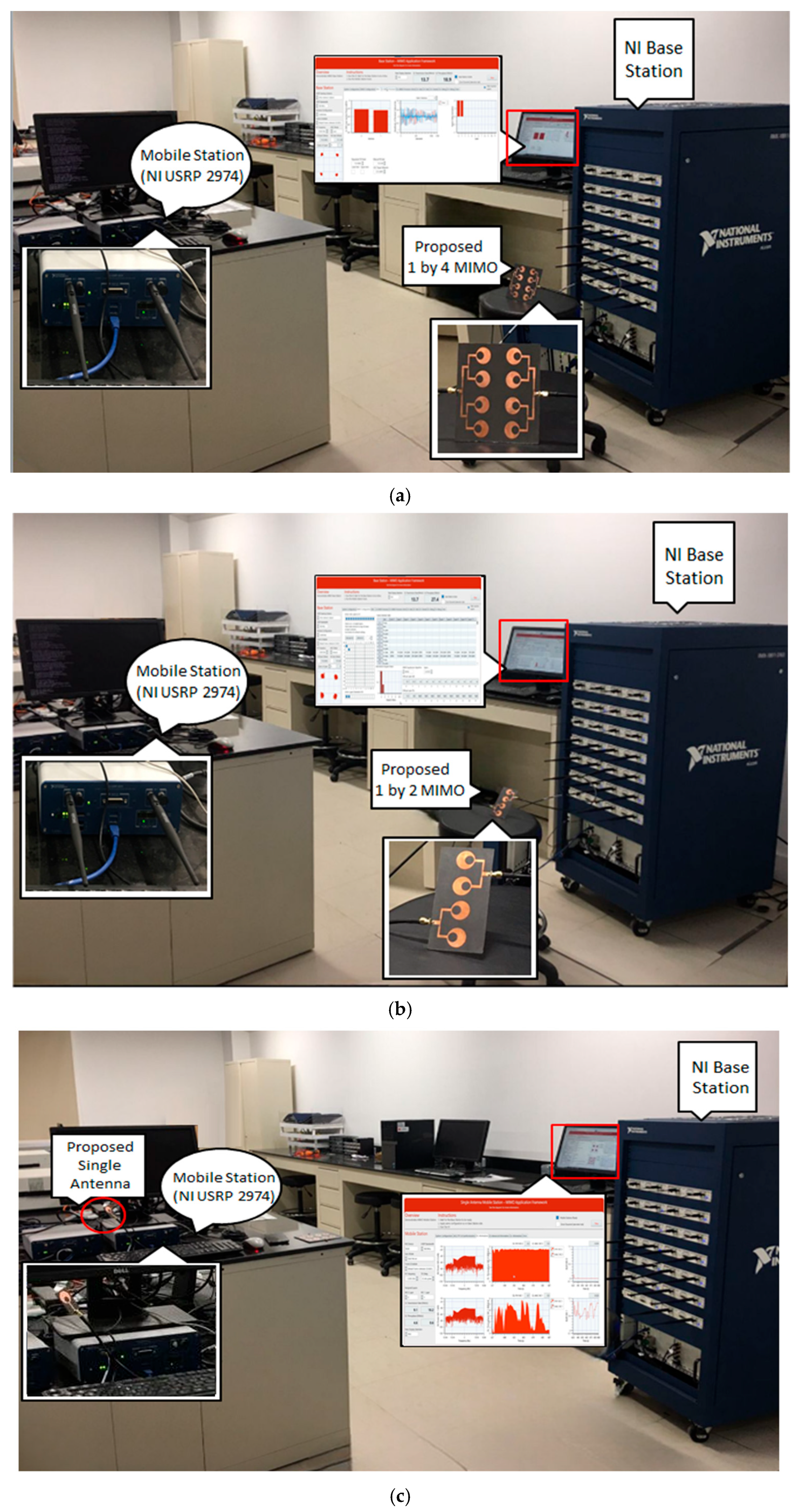
5. Experimental Testing of the Proposed Antennas Within the 5G MIMO Application Framework

The MIMO Application Framework (LabVIEW Communications) provides licensed software for a customizable real-time MIMO reference design relevant to the LTE standard. This MIMO Application Framework features an FPGA-based software reference design that supports a fully streaming, real-time physical layer for both uplink and downlink at 20 MHz TDD, adhering to the LTE standard.
The three proposed fabricated antennas were implemented and experimentally tested using the MIMO Application Framework for 5G systems, which operates in the sub-6 GHz range. The testing took place at the Next Generation Wireless Communication Technologies Laboratory for Smart Cities at the Egypt-Japan University of Science and Technology.
The MIMO Application Framework comprises two primary components: the multi-antenna mobile station (MS) and the multi-antenna base station (BS). Both the multi-antenna BS and the multi-antenna MS represent the most complex system elements supported by the MIMO Application Framework.
The base station includes a PXIe-8135 controller and can accommodate between one and eight PXIe-8384 MXI-Express modules for communication with USRP devices. It also supports up to five PXIe-7976 modules, depending on the number of USRP subsystems installed in a PXIe-1085 chassis. The mobile station supports an even number of antennas, ranging from two to twelve. A multi-antenna MS uses the same general hardware setup as a 16-antenna BS. The number of USRP devices, which serve as remote radio heads (RRHs), can be lower and is determined by the number of antennas, with two antennas supported for each USRP device. Three antennas are connected indoors to the BS and MS ports. Subsequently, a computer is connected to the USRP antenna via a USB cable, while an Ethernet cable links the system to a router for Internet access. Figure 27 presents the implementation of MIMO of two 1 × 4 arrays, MIMO of two 1 × 2 arrays, and a single element on the 5G MIMO Application Framework, respectively.
Once the system is established, the three antennas are connected to the USRP, configured, compiled, and executed. Finally, mobile phones are connected to the cellular networks. Table 9 presents the key environmental parameters for the 5G experimental test based on the MIMO Application Framework.
The three fabricated antennas, MIMO of two 1 × 4 arrays, MIMO of two 1 × 2 arrays, and the single element, were implemented and experimentally tested using the MIMO Application Framework 5G Systems, extracting a group of telemetry parameters.
Figure 28a presents a comparison between the three antennas, showing that the signal to noise ratio at different transmitted power varies from 0 to 15 dBm at 3.5 GHz at 2.5 m as a line of site (LOS) distance; these results suggest the proposed MIMO of two 1 × 4 arrays demonstrates better performance compared with the two proposed antennas. SNR varies from 13–20 dB, which indicates good quality. The MIMO of two 1 × 4 arrays reaches 25 dB, indicating a performance of excellent quality with a high data rate and stable connection. Figure 28b compares the signal strength performance of three antennas. The proposed MIMO configuration with two 1 × 4 arrays achieves a signal strength of −10 dBFS (decibels relative to full scale) per element, which is better than the −24 dBFS and −34 dBFS of the MIMO with two 1 × 2 arrays and a single antenna element, respectively.
In the dBFS scale, 0 dBFS indicates maximum signal strength, −1 to −10 dBFS represents strong signals, −20 to −40 dBFS indicates medium strength, and −60 dBFS or lower is considered weak. Table 10 shows the main performance parameters of the 5G experimental test based on the MIMO Application Framework system, which shows that MIMO antennas have a higher Mbit/s value, indicating a faster data transfer rate equal to 13.7 Mbit/s compared with 4.7 Mbit/s for a single element, as >10 Mbit/s is a typical range for sub 6 GHz. The MIMO of two 1 × 4 arrays offer: higher throughput of data; it could deliver over a communication channel in a network of 27.4 Mbit/s compared with the two other antennas, which is maximum power level that a signal can achieve without distortion or clipping.
The performance of three antennas was evaluated under identical conditions. The 2-port MIMO configuration with two 1 × 4 arrays outperformed the 2-port MIMO with two 1 × 2 arrays and a single antenna that has 10.9 dBi and 97.46% radiation efficiency. The 2-port MIMO with two 1 × 4 arrays provides better data rates, higher throughput, and lower error rates, making it ideal for high-speed applications like video streaming and 5G. On the other hand, the 2-port MIMO with two 1 × 2 arrays is reliable for standard Wi-Fi and IoT devices, due to its lower error rates. The single antenna needs stable communication and has lower throughput, making it suitable for short-range devices and non-critical data.
This can be explained by a high-gain antenna focusing the signal more effectively in a desired direction, which boosts the received signal power from the transmitter without increasing the noise floor. Higher gain leads to more effective radiated power (ERP) in the main direction. Signal strength is directly related to received power, so improvements in gain or efficiency enhance signal strength. The SNR, which is the ratio of signal power to noise power, improves with increased signal power if the noise level remains constant. A higher SNR leads to better decoding, lower bit error rates, and more reliable communication, especially under weak signal conditions or interference. So, a 2-port MIMO with two 1 × 4 array antennas with high antenna gain and efficiency positively influences how much useful energy is radiated and collected, ultimately determining signal strength and its ability to be distinguished from noise in wireless communication systems, compared with the 2-port MIMO with two 1 × 2 arrays and single-element antennas.

6. Conclusions

Various MIMO antennas function within the sub-6 GHz frequency range, using an RT5880 substrate. One design features a single circular antenna that operates between 2.96 GHz and 7.1 GHz. A MIMO of two 1 × 2 arrays was created to support dual-band operation, covering both 2.27 GHz to 4.94 GHz and 5.53 GHz to 7.84 GHz, as a measured result, resulting in a maximum gain of 8.3 dBi, a maximum radiation efficiency of up to 95% and demonstrating strong MIMO performance. Additionally, a MIMO of two 1 × 4 arrays was designed for triple-band coverage at 2.33 GHz to 4.02 GHz, 4.25 GHz to 4.4 GHz, and 4.6 GHz to 6.62 GHz as a measured result, yielding a maximum gain of 10.9 dBi, maximum radiation efficiency of up to 97.46% and effective MIMO performance metrics: ECC values were below 0.006 and 0.003 for the respective bands, while CCL values were under 0.4 and 0.3, respectively. Finally, the three fabricated antennas were experimentally tested and implemented using the MIMO Application Framework for 5G systems, demonstrating operational effectiveness in 5G applications.

Author Contributions

Conceptualization, H.A. and A.M.A.; Methodology, H.A. and A.M.A.; Software, H.A.; Validation, H.A. and A.M.A.; Formal analysis, A.M.A.; Investigation, A.M.A.; Resources, A.M. and A.N.; Writing—original draft, H.A.; Writing—review & editing, A.M.; A.N. and M.A.-Z.; Supervision, A.M.A.; A.M.; A.N. and M.A.-Z. All authors have read and agreed to the published version of the manuscript.

Funding

This research received no external funding.

Data Availability Statement

The original contributions presented in this study are included in the article. Further inquiries can be directed to the corresponding author.

Acknowledgments

The authors thank the Egypt-Japan University of Science and Technology, Egypt, and the Egyptian Science, Technology and Innovation Funding Authority (STDF) for facilitating the testing of the designed antennas at the Next Generation Wireless Communication Technologies Laboratory for Smart Cities through STDF Project No. 38285.

Conflicts of Interest

The authors declare no conflict of interest.

References

  1. Tiwari, R.N.; Thirumalaiah, R.; Naidu, V.R.; Sreenivasulu, G.; Singh, P.; Rajasekaran, S. Compact dual-band 4-port MIMO antenna for 5 G-sub 6 GHz/N38/N41/N90 and WLAN frequency bands. AEU-Int. J. Electron. Commun. 2023, 171, 154919. [Google Scholar] [CrossRef]
  2. Din, I.U.; Alibakhshikenari, M.; Virdee, B.S.; Ullah, S.; Ullah, S.; Akram, M.R.; Ali, S.M.; Livreri, P.; Limiti, E. High-performance antenna system in MIMO configuration for 5G wireless communications over sub-6 GHz spectrum. Radio Sci. 2023, 58, 1–22. [Google Scholar] [CrossRef]
  3. Tulum, M.A.; Turk, A.S.; Mahouti, P. Data-driven surrogate modeling of phase array antennas using deep learning for millimetric band applications. IEEE Access 2023, 11, 114415–114423. [Google Scholar] [CrossRef]
  4. Van Messem, L.; Moerman, A.; Caytan, O.; de Paula, I.L.; Hoflack, B.; Stroobandt, B.; Lemey, S.; Moeneclaey, M.; Rogier, H. A 4 × 4 millimeter-wave-frequency Butler matrix in grounded co-planar waveguide technology for compact integration with 5G antenna arrays. IEEE Trans. Microw. Theory Tech. 2022, 71, 122–134. [Google Scholar] [CrossRef]
  5. Azim, R.; Aktar, R.; Siddique, A.K.M.M.H.; Paul, L.C.; Islam, M.T. Circular patch planar ultra-wideband antenna for 5G sub-6 GHz wireless communication applications. J. Optoelectron. Adv. Mater. 2021, 23, 127–133. [Google Scholar]
  6. Shamoon, S.; Zhou, W.Y.; Shahzad, F.; Ali, W.; Subbyal, H. Integrated sub-6 GHz and millimeter wave band antenna array modules for 5G smartphone applications. AEU-Int. J. Electron. Commun. 2023, 161, 154542. [Google Scholar] [CrossRef]
  7. Khorasani, S.A.; Zakeri, H.; Moradi, G.; Alibakhshikenari, M.; See, C.H.; Limiti, E. Orbital angular momentum with the approach of using in sub-6GHz 5G mobile communications for wireless applications. In Proceedings of the 2024 6th Global Power, Energy and Communication Conference (GPECOM), Budapest, Hungary, 4–7 June 2024; pp. 1–4. [Google Scholar]
  8. Zakeri, H.; Shirazi, R.S.; Moradi, G. An accurate model to estimate 5g propagation path loss for the indoor environment. arXiv 2023, arXiv:2302.10057. [Google Scholar] [CrossRef]
  9. Jayaprakash, V.; Chandu, D.S.; Barik, R.K.; Koziel, S. Compact Substrate-Integrated Hexagonal Cavity-Backed Self-Hexaplexing Antenna for Sub-6 GHz Applications. IEEE Access 2024, 12, 54397–54404. [Google Scholar] [CrossRef]
  10. Mohanty, A.; Sahu, S. 4-port UWB MIMO antenna with Bluetooth-LTE-WiMax band-rejection and vias-MCP loaded reflector with improved performance. AEU-Int. J. Electron. Commun. 2022, 144, 154065. [Google Scholar] [CrossRef]
  11. Hu, K.; Zhou, Y.; Sitaraman, S.K.; Tentzeris, M.M. Additionally, manufactured flexible on-package phased array antennas for 5G/mmWave wearable and conformal digital twin and massive MIMO applications. Sci. Rep. 2023, 13, 12515. [Google Scholar]
  12. Mahto, S.K.; Singh, A.K.; Sinha, R.; Alibakhshikenari, M.; Khan, S.; Pau, G. Highly isolated four-element MIMO antenna for ISM/LTE/5G (Sub-6GHz) applications. IEEE Access 2023, 11, 82946–82959. [Google Scholar] [CrossRef]
  13. Liu, H.Y.; Huang, C.J. Wideband MIMO antenna array design for future mobile devices operating in the 5G NR frequency bands n77/n78/n79 and LTE band 46. IEEE Antennas Wirel. Propag. Lett. 2019, 19, 74–78. [Google Scholar]
  14. Thummaluru, S.R.; Ameen, M.; Chaudhary, R.K. Four-port MIMO cognitive radio system for midband 5G applications. IEEE Trans. Antennas Propag. 2019, 67, 5634–5645. [Google Scholar] [CrossRef]
  15. Kulkarni, J.S.; Sim, C.Y.D. Low-profile, multiband wideband ‘C-shaped’ monopole antenna for 5G and WLAN applications. In Proceedings of the 2020 International Conference on Radar, antenna, Microwave, Electronics, and Telecommunications (ICRAMET), Tangerang, Indonesia, 18–20 November 2020; pp. 366–371. [Google Scholar]
  16. Li, Y.; Zou, H.; Wang, M.; Peng, M.; Yang, G. Eight-element MIMO antenna array for 5G/Sub-6GHz indoor micro wireless access points. In Proceedings of the 2018 International Workshop on Antenna Technology (iWAT), Nanjing, China, 5–7 March 2018; pp. 1–4. [Google Scholar]
  17. Ren, Z.; Wu, S.; Zhao, A. Triple band MIMO antenna system for 5G mobile terminals. In Proceedings of the 2019 International Workshop on Antenna Technology (iWAT), Miami, FL, USA, 3–6 March 2019; pp. 163–165. [Google Scholar]
  18. Zhang, Y.M.; Zhang, S.; Li, J.L.; Pedersen, G.F. A transmission-line-based decoupling method for MIMO antenna arrays. IEEE Trans. Antennas Propag. 2019, 67, 3117–3131. [Google Scholar] [CrossRef]
  19. Al-Turjman, F.; Ever, E.; Zahmatkesh, H. Small cells in the forthcoming 5G/IoT: Traffic modelling and deployment overview. IEEE Commun. Surv. Tutor. 2018, 21, 28–65. [Google Scholar] [CrossRef]
  20. Hussain, R.; Raza, A.; Khan, M.U.; Shammim, A.; Sharawi, M.S. Miniaturized frequency reconfigurable pentagonal MIMO slot antenna for interweave CR applications. Int. J. RF Microw. Comput.-Aided Eng. 2019, 29, e21811. [Google Scholar] [CrossRef]
  21. Ta, S.X.; Nguyen, D.M.; Nguyen, K.K.; Dao-Ngoc, C.; Nguyen-Trong, N. A tripolarized antenna with ultrawide operational bandwidth. IEEE Trans. Antennas Propag. 2020, 68, 4386–4396. [Google Scholar] [CrossRef]
  22. Wong, K.L.; Chen, J.Z.; Li, W.Y. Four-port wideband annular-ring patch antenna generating four decoupled waves for 5G multi-input–multi-output access points. IEEE Trans. Antennas Propag. 2020, 69, 2946–2951. [Google Scholar] [CrossRef]
  23. Molins-Benlliure, J.; Antonino-Daviu, E.; Cabedo-Fabrés, M.; Ferrando-Bataller, M. Four-port wide-band cavity-backed antenna with isolating X-shaped block for sub-6 GHz 5G indoor base stations. IEEE Access 2021, 9, 80535–80545. [Google Scholar] [CrossRef]
  24. Zhang, E.; Michel, A.; Pino, M.R.; Nepa, P.; Qiu, J. A dual circularly polarized patch antenna with high isolation for MIMO WLAN applications. IEEE Access 2020, 8, 117833–117840. [Google Scholar] [CrossRef]
  25. Singhwal, S.S.; Kanaujia, B.K.; Singh, A.; Kishor, J.; Matekovits, L. Multiple-input multiple-output dielectric resonator antenna with circular polarized adaptability for 5G applications. J. Electromagn. Waves Appl. 2020, 34, 1180–1194. [Google Scholar] [CrossRef]
  26. Molins-Benlliure, J.; Cabedo-Fabrés, M.; Antonino-Daviu, E.; Ferrando-Bataller, M. Sector unit-cell methodology for the design of Sub-6 GHz 5G MIMO antennas. IEEE Access 2022, 10, 100824–100836. [Google Scholar] [CrossRef]
  27. Nahar, T.; Rawat, S.; Pathak, P.; Kumar, P.; Anguera, J. Leaf-shaped antennas for Sub-6 GHz 5G applications. IEEE Access 2024, 12, 114338–114357. [Google Scholar] [CrossRef]
  28. Zakeri, H.; Azizpour, R.; Khoddami, P.; Moradi, G.; Alibakhshikenari, M.; See, C.H.; Denidni, T.A.; Falcone, F.; Koziel, S.; Limiti, E. Low-cost multiband four-port phased array antenna for sub-6 GHz 5G applications with enhanced gain methodology in radio-over-fiber systems using modulation instability. IEEE Access 2024, 12, 117787–117799. [Google Scholar] [CrossRef]
  29. Khan, S.; Marwat, S.N.K.; Khan, M.A.; Ahmed, S.; Gohar, N.; Alim, M.E.; Algarni, A.D.; Elmannai, H. A Self-Decoupling Technique to Realize Dense Packing of Antenna Elements in MIMO Arrays for Wideband Sub-6 GHz Communication Systems. Sensors 2023, 23, 654. [Google Scholar] [CrossRef]
  30. Jin, G.; Deng, C.; Xu, Y.; Yang, J.; Liao, S. Differential frequency-reconfigurable antenna based on dipoles for sub-6 GHz 5G and WLAN applications. IEEE Antennas Wirel. Propag. Lett. 2020, 19, 472–476. [Google Scholar] [CrossRef]
  31. Liu, P.; Meng, Z.; Wang, L.; Zhang, Y.; Li, Y. Omnidirectional dual-polarized saber antenna with low wind drag. IEEE Trans. Antennas Propag. 2019, 68, 558–563. [Google Scholar] [CrossRef]
  32. Li, Q.L.; Cheung, S.W.; Wu, D.; Yuk, T.I. Optically transparent dual-band MIMO antenna using micro-metal mesh conductive film for WLAN system. IEEE Antennas Wirel. Propag. Lett. 2016, 16, 920–923. [Google Scholar] [CrossRef]
  33. Ameen, A.M.; Ahmed, M.I.; Elsadek, H.; Anis, W.R. Design of 4-direction MIMO Vivaldi antenna system for vehicle communication in 5G applications. J. Electromagn. Waves Appl. 2022, 36, 2027–2040. [Google Scholar] [CrossRef]
  34. Alharbi, A.G.; Rafique, U.; Ullah, S.; Khan, S.; Abbas, S.M.; Ali, E.M.; Alibakhshikenari, M.; Dalarsson, M. Novel MIMO antenna system for ultra-wideband applications. Appl. Sci. 2022, 12, 3684. [Google Scholar] [CrossRef]
  35. Ho Chae, S.; Il Kawk, W.; Park, S.O.; Lee, K. Analysis of mutual coupling in MIMO antenna array by TARC calculation. In Proceedings of the 2006 Asia-Pacific Microwave Conference, Yokohama, Japan, 12–15 December 2006; pp. 2090–2093. [Google Scholar]
  36. Fang, Y.; Jia, Y.; Zhu, J.Q.; Liu, Y.; An, J. Self-decoupling, shared-aperture, eight-antenna MIMO array with MIMO-SAR reduction. IEEE Trans. Antennas Propag. 2023, 72, 1905–1910. [Google Scholar] [CrossRef]
  37. Jiang, J.Y.; Su, H.L. A Wideband Eight-Element MIMO Antenna Array in 5G NR n77/78/79 and WLAN-5GHz Bands for 5G Smartphone Applications. Int. J. Antennas Propag. 2022, 2022, 8456936. [Google Scholar] [CrossRef]
  38. Kiani, S.H.; Savci, H.S.; Abubakar, H.S.; Parchin, N.O.; Rimli, H.; Hakim, B. Eight-element MIMO antenna array with tri-band response for modern smartphones. IEEE Access 2023, 11, 44244–44253. [Google Scholar] [CrossRef]
  39. Kulkarni, N.; Linus, R.M.; Bahadure, N.B. A small, wideband, inverted L-shaped flexible antenna for sub-6 GHz 5G applications. AEU-Int. J. Electron. Commun. 2023, 159, 154479. [Google Scholar] [CrossRef]
  40. John, D.M.; Vincent, S.; Pathan, S.; Shinde, K.D.; Supreetha, B.S.; Ali, T. Eight-Element Flexible MIMO Antenna Based on Characteristics Mode Theory with Enhanced Channel Capacity for Sub 6 GHz 5G Communications. Results Eng. 2025, 25, 104208. [Google Scholar] [CrossRef]
Figure 1. The single antenna simulated design: (a) top view and (b) back view, fabricated prototype element, (c) top view and (d) back view, and (e) input impedance over frequency.
Telecom 06 00053 g001
Figure 2. The measured and simulated S11 of the single design.
Telecom 06 00053 g002
Figure 3. The measured and simulated gain of the single design.
Telecom 06 00053 g003
Figure 4. The E-plane: (a) measured and simulated at 3.5 GHz; (b) at 5.8 GHz, and (c) radiation pattern and gain setup.
Telecom 06 00053 g004
Figure 5. Design development for (a) the 1st, (b) the 2nd, and (c) the 3rd iteration.
Telecom 06 00053 g005
Figure 6. S11 for (1) the 1st, (2) the 2nd, and (3) the 3rd iteration.
Telecom 06 00053 g006
Figure 7. Current distribution for (a) the centered slot and (b) the shifted down slot.
Telecom 06 00053 g007
Figure 8. Parametric analysis results for variation of (a) r and (b) c for (S11).
Telecom 06 00053 g008
Figure 9. Simulated design: (a) the 1 × 2 array’s top side, (b) the back side, and (c) input impedance over frequency.
Telecom 06 00053 g009
Figure 10. The simulated S11 of the 1 × 2 design.
Telecom 06 00053 g010
Figure 11. The simulated gain of the 1 × 2 design.
Telecom 06 00053 g011
Figure 12. The E-plane: (a) simulated at 3.5 GHz; (b) at 5.8 GHz, of 1 × 2 design.
Telecom 06 00053 g012
Figure 13. The MIMO of two 1 × 2 arrays: (a) the simulated top side, (b) back side, (c) fabricated prototype top side, (d) back side, and (e) radiation efficiency.
Telecom 06 00053 g013
Figure 14. A comparison of: (a) the measured and simulated S11, S22, and (b) the S12 and S21, of the MIMO of two 1 × 2 arrays design.
Telecom 06 00053 g014
Figure 15. A Comparison of: (a) measured and simulated (E-plane) at 3.5 GHz, (b) at 5.8 GHz, of MIMO of two 1 × 2 arrays, and (c) radiation pattern and gain setup.
Telecom 06 00053 g015
Figure 16. The measured and the simulated gain of the MIMO of two 1 × 2 arrays.
Telecom 06 00053 g016
Figure 17. MIMO parameters of Two 1 × 2 Arrays: (a) measured and simulated CCL, (b) the ECC, (c) the DG, (d) the TARC, and (e) the MEG.
Telecom 06 00053 g017
Figure 18. The 1 × 4 array: (a) the simulated top side, (b) the back side, and (c) input impedance over frequency.
Telecom 06 00053 g018
Figure 19. The simulated S11 of the 1 × 4 array.
Telecom 06 00053 g019
Figure 20. The simulated gain of the 1 × 4 array.
Telecom 06 00053 g020
Figure 21. The E-plane radiation pattern: (a) measured and simulated at 3.5 GHz; and (b) at 5.8 GHz.
Telecom 06 00053 g021
Figure 22. The MIMO of two 1 × 4 arrays: (a) the simulated top side, (b) the back side, (c) the fabricated prototype top side, (d) the back side, and (e) radiation efficiency.
Telecom 06 00053 g022
Figure 23. A comparison of: (a) the measured and simulated S11, S22, and (b) the S12 and S21.
Telecom 06 00053 g023
Figure 24. E-plane radiation pattern: (a) measured and simulated at 3.5 GHz, (b) at 5.8 GHz, and (c) radiation pattern and gain setup.
Telecom 06 00053 g024
Figure 25. The measured and simulated gain of the MIMO of two 1 × 4 arrays.
Telecom 06 00053 g025
Figure 26. MIMO parameters of Two 1 × 4 Arrays: (a) measured and simulated CCL, (b) the ECC, (c) the DG, (d) the TARC, and (e) the MEG.
Telecom 06 00053 g026
Figure 27. MIMO application framework implementation for: (a) MIMO of two 1 × 4 arrays, (b) MIMO of two 1 × 2 arrays, (c) Single element.
Telecom 06 00053 g027
Figure 28. Comparison of MIMO of two 1 × 4 arrays, MIMO of two 1 × 2 arrays, and single element for: (a) SNR and (b) signal strength.
Telecom 06 00053 g028
Table 1. Single element dimensions.
ParameterSubstrate WidthSubstrate Lengthr1r2Lf1Lf2WfcWgLg
(mm)304612517.3514.2143015
Table 2. Comparison of the proposed single design with previous studies.
Ref. No.AreaBandwidthMax GainMax Efficiency %
[30]50 × 502.89–4.07
5.1–6.19
2.6-
[31]30 × 292.38–2.771.4274
[32]40 × 402.36–2.740.7446
5.14–6.182.3
Proposed single antenna30 × 462.96–7.14.384
Table 3. Dimensions of the 1 × 2 design.
ParameterSubstrate WidthSubstrate LengthWfLFW1W2L1L2WgLg
(mm)66604.21101013.0413116620.89
Table 4. Dimensions of two 1 × 2 arrays MIMO.
ParameterSubstrate WidthSubstrate LengthW1W2WgWsLg
(mm)1326630.7396.69660.120.89
Table 5. Comparison of the proposed MIMO of two 1 × 2 arrays with previous studies.
Ref. No.SizeBandwidthMax GainMax
Efficiency %
ECC
[27]85 × 97.73 × 1.63.43–3.9
4.61–4.99
6.5670-
[36]160 × 75 × 7.53.4–3.6->55<0.1
[37]150 × 75 × 7.83.3–3.6-60<0.31
[38]150 × 75 × 73.1–65.865<0.02
[39]95 × 65 × 0.23.05–3.072.2-<0.1
Proposed
MIMO of two 1 × 2 arrays
132 × 66 × 1.572.27–4.94
5.53–7.84
8.395<0.006
Table 6. Dimensions of the 1 × 4 array.
ParameterSubstrate WidthSubstrate LengthWfLFW1W2W3L1L2Lg
(mm)140664.217.72161215131027.67
Table 7. Dimensions of the two 1 × 4 arrays MIMO.
ParameterSubstrate WidthSubstrate LengthL1L2L3W1
(mm)14013218.476.6627.671
Table 8. Comparison of the proposed MIMO of two 1 × 4 arrays design with previous studies.
Ref.SizeBandwidthGainECCSubstrateMaterialMax
Efficiency %
ApplicationTechnique
[21]180 × 180 × 2.71.68–4.158.4–9.40.0005Fr-4-5GM-shape strip
[22]150 × 150 × 103.3–55.2–6.8˂0.05Fr-4845GAnnular-ring
[23]129.5 × 129.5 × 28.21.55–64–10˂0.5-845GCavity-backed
[24]157 × 96 × 1.532.4–2.580.004Fr-4-WLANTapered Stub
[25]110 × 110 × 0.83.12–3.97.30.3ROGER RT Duriod905GCylindrical DRA
[26]190.5 × 190.5 × 331.27–64–11˂0.1R04003C82WIFIMIMO
[28]110 × 110 × 0.7873–5.55.2–7.8-Fr-4-5GPhased array antenna
[40]135 × 135 × 0.13.92–5.053.7˂0.05Polyethylene terephthalate (PET)745GCavity-backed
Proposed
MIMO of two 1 × 4 arrays
140 × 132 × 1.572.33–4.02
4.25–4.4
4.6–6.62
8–10.9˂0.003RT588097.465G/Sub-6GHzMIMO-array
Table 9. MIMO application framework environmental parameters.
ParameterFreqChannel B. WLOSTX PowerDuplexingNoise Floor
value3.5 GHz120 MHz2.5 m0–15 dBmTDD5 dB
Table 10. MIMO application framework performance parameters.
ParameterSingle ElementMIMO of Two
1 × 2 Arrays
MIMO of Two
1 × 4 Arrays
DL transmission rate (Mbit/s)4.613.713.7
UL throughput (Mbit/s)9.123.227.4
Disclaimer/Publisher’s Note: The statements, opinions and data contained in all publications are solely those of the individual author(s) and contributor(s) and not of MDPI and/or the editor(s). MDPI and/or the editor(s) disclaim responsibility for any injury to people or property resulting from any ideas, methods, instructions or products referred to in the content.

