Review

Wideband Mixed Signal Separation Based on Photonic Signal Processing

Department of Electrical and Computer Engineering, Rowan University, Glassboro, NJ 08028, USA
*
Author to whom correspondence should be addressed.
Telecom 2021, 2(4), 413-429; https://doi.org/10.3390/telecom2040024
Submission received: 13 September 2021 / Revised: 15 October 2021 / Accepted: 28 October 2021 / Published: 2 November 2021
(This article belongs to the Special Issue Advances in Optical Wireless Communication)

Abstract

:
The growing needs for high-speed and secure communications create an increasing challenge to the contemporary framework of signal processing. The coexistence of multiple high-speed wireless communication systems generates wideband interference. To protect the security and especially the privacy of users’ communications requires stealth communication that hides and recovers private information against eavesdropping attacks. The major problem in interference management and stealth information recovery is to separate the signal of interest from wideband interference/noise. However, the increasing signal bandwidth presents a real challenge to existing capabilities in separating the mixed signal and results in unacceptable latency. The photonic circuit processes a signal in an analog way with a unanimous frequency response over GHz bandwidth. The digital processor measures the statistical patterns of the signals with sampling rate orders of magnitude smaller than the Nyquist frequency. Under-sampling the signals significantly reduces the workload of the digital processor while providing accurate control of the photonic circuit to perform the real-time signal separations. The wideband mixed signal separation, based on photonic signal processing is scalable to multiple stages with the performance of each stage accrued.

1. Introduction

High-speed communications boost economic growth by supporting a wide range of applications that are changing the way that Americans live, including the internet of things, unmanned vehicle systems, radars for transportation, and cyber physical systems, to name a few. Private communication protects civilians, as well as empowers homeland security, by preventing confidential information from being exposed and are increasingly important in a connected world. Therefore, the availability of high-speed communications and whether the communication is protected from eavesdropping are two key considerations of building a communication network. Interference management has been widely deployed to enable the availability of wireless communication channels [1], and stealth communication hides the existence of the signal and protects users’ privacy in the physical layer [2,3]. Both interference management and stealth communication require the processing and separation of the signal of interest (SOI) from interference and noise in real-time, while the growing needs of communication dramatically increase the bandwidth of the signals and thus create an increasing challenge to the contemporary framework of signal processing.
This review introduces the current Interference management and stealth communication systems, the challenges, and the feasibility of hybrid systems that address the growing needs of wideband real-time signal processing by leveraging the mutual benefits of photonic signal processing. Optical communication uses light to transfer information, and photonic signal processing technique uses optical spectrum to analyze, modify, and synthesize, which are inherently compatible with fiber-optic communication systems. Photonic methods have been demonstrated to directly process the wideband analog the signal with zero latency [4,5,6]. By using photonic methods to remove interference, the bandwidth and dynamic range of the signal are greatly reduced for the digital edge device to process. On the other hand, the photonic methods require strict matching conditions between physical parameters to achieve optimized signal separation. Such a matching condition can be easily identified in a point-to-point stationary link [7], while in a network, the physical parameters, such as wireless channel coefficients, private keys to recover the stealth signal, scales up with the number of nodes in the network and is changing over time. Such a change cannot be tracked simply with the photonic system. By using the edge device to dynamically measure the statistical pattern of the mixed signal, the change in the physical parameters can be followed, and the edge device can accurately control the photonic system to achieve the matching condition and perform signal separation.
The capability of separating wideband signals impact communication availability and confidentiality through two fundamentals, while not yet solving problems in communications: interference management and stealth communication. The core of both problems is to separate the SOI from interference and noise.
Interference management: Separation SOI from unknown signals, also known as blind source separation (BSS), enables multiple wireless systems to share the same radio frequency (RF) spectrum at the same time. As a scarce resource, the RF spectrum is simultaneously being used with multiple wireless communication protocols and thus interference is generated between systems [8,9]. The bandwidth and the power dynamic range of the separation system determine whether multiple wireless systems can coexist in the same band.
Stealth communication: Separation SOI from pre-known signals or intentionally added noise enables stealth communication. A stealth method, such as spread spectrum technique, prohibits eavesdropper access by hiding signals in wideband noise, while it also increases the difficulties of authorized users with the right keys [10,11]. A large amount of data needs to be processed to separate the signal from the wideband noise. With the growing need for communication capacities and requirements of privacy, the bandwidth of the separation system determines the effectiveness of the stealth transmission methods.
To solve the communication problems with an optimized balance between physical level new methods and software level innovations. The communication network is a symphony of progressively evolving techniques in both hardware and software levels. Without knowing the physical background of the hardware tools, the software methods are limited by the fixed parameters of the hardware, such as channel bandwidth, data rate, and ADC resolution, and its lack of overall control of the system by using the emerging techniques of hardware. The future perspectives of a hybrid analog and digital system pave the way for the long-term goal by breaking the bandwidth limit of high speed and secure communications to adjust the current background of the migration from 4G to 5G, and potential application to embrace new generations (6G and more) with unprecedented challenges. The fundamental idea of collaborative innovations in both hardware and software will continue shaping the network.

2. Interference Management

2.1. Related Work

The simplest scenario for interference management systems includes a SOI transmitter, an interference transmitter, and a receiver, all equipped with MIMO transmitting/receiving antennas (Figure 1), while is scalable to networks with a larger number of transmitting and receiving nodes. The left MIMO antennas receive x 1 and x 2 , both of which are combinations of SOI s s o i   and interference s i n t in the same RF band:
X = A S ,   or   [ x 1 x 2 ] = [ a 11 a 12 a 21 a 22 ] [ s s o i s i n t ]  
where A is the mixing matrix and depends on the channel coefficients. To separate the SOI from the interference is to find the inverse of the mixing matrix, S = A 1 X .
The experimental results include an algorithm for the digital edge device to perform principal component analysis (PCA) and independent component analysis (ICA) with under-sampled signal and the photonic circuit hardware that separates the wideband signals in real-time.

2.1.1. Photonic Circuit

The photonic circuit has two major functions [12,13]: (1) it adds an arbitrary complex weight to each of the received signals x i ; (2) the weighted signal is summed and, by choosing the right weight, the mixed signal is separated as S = A 1 X . Figure 2 is the schematic diagram of the photonic circuit and has been demonstrated with both discrete components [14,15] and integrated chips [16,17,18]. In Figure 2, there are two channels, which correspond to two MIMO inputs ( x 1 and x 2 ). The number of channels can be scalable to n ( n > 16 ) by using the WDM technique if the interference source is more than one [18,19]. The mixed RF signals are modulated on optical carriers with center frequency 193 THz. The bandwidth of the so-called wideband RF signals is extremely narrow, compared with the optical carriers.
Experimental results show that the systems process the signals in real-time and reach a 30 dB cancellation ratio with bandwidth from 500 MHz to 3.5 GHz [12,14,17]. The cancellation ratio describes the capability of the system to separate the mixed signals and is measured by the cancellation ratio between the interference separated from the mixed signal to the interference that remains mixed with the signal. The cancellation ratio is limited by the non-uniform frequency response of RF devices and digitization error in digital systems. When the bandwidth of the mixed signal is beyond 1 GHz, the current state-of-the-art ADC is limited to 4–8 bits resolution, which corresponds to 12–24 dB of cancellation ratio. Using optical carriers to process the mixed-signal and cancel the interference has a unanimous frequency response and as an analog method, the cancellation ratio is not limited by the ADC resolution. Table 1 shows the cancellation ratio at different bandwidths by using the photonics method [12,14,17]; all works are summarized in Table A2 in Appendix A.
The interference source and interference frequency vary in each of the setups. The interference bandwidth varies from 500 MHz to 3.5 GHz. For the optical encryption system [12], the interference noise is generated as an RF sine wave with its frequency changing between 4 GHz to 7 GHz, and applied to a laser frequency of 1550.12 nm, the bandwidth of the interference is tested from 4 GHz to 7 GHz with an average cancellation of 26 dB, which is wide enough to encrypt and protect a signal with the data rate of 10 Gb/s. For radio frequency spectrum control [14], the interference signal is set as an RF sine wave of 1 GHz, applied to a 1544.3 nm laser source. The system is tested to achieve average cancellation of 26 dB from 500 MHz to 5 GHz via a Keysight E5063A Network Analyzer. For optical self-interference cancellation [17], the signal of interest was set as a weak 915 MHz single-tone signal, and the interference was set as a sweeping 0 dBm single-tone interferer across 60 MHz bandwidth cantered at 915 MHz, where the 60 MHz bandwidth is greater than most channel bandwidth, used in common LTE or Wi-Fi protocols; a 38 dB cancellation is achieved across the 60 MHz bandwidth, and a 56 dB cancellation is achieved when using a 10 kHz bandwidth interference.

2.1.2. Digital System

The digital system measures the statistical pattern with the under-sampled signal and controls the photonic circuits with tunable weights and delays (TD and TA in Figure 2) to perform the separation. Figure 3 shows the mixed signal x 1 and x 2 . Both s s o i and s i n t have Gaussian distribution. The BSS is to solve the inverse of the mixing matrix A and include two steps: PCA and ICA [20,21,22], symbols used in this section are listed in Table A1 in Appendix A.
A 1 = V U Σ U 1  
where U Σ U 1 represents the PCA, and V represents the ICA. To perform PCA, the 2nd order moments of the mixed signal with different weights are calculated. By using the tunable optical attenuators in the photonic circuit (TA in Figure 2), the following weight is added to the mixed signal:
x P C A = cos ( θ ) x 1 + sin ( θ ) x 2    
where θ is defined in Figure 3. The second order moment of x P C A is a function of θ (red curve in Figure 3), and is in the form of:
E ( x P C A 2 ) = q 1 + q 2 cos [ 2 ( θ θ 0 ) ]  
where E ( x P C A 2 )   is the expectation or time average of x P C A 2 ,which is referred to as a two-petal epitrochoid, has a clear relation to the principal components [22]. The first principal components vector angle (direction) is θ 0 , and the second is orthogonal. The q and θ parameters describe all the covariance properties of the joint distribution. q 1 + q 2 is the magnitude of the first component, and q 1 q 2 is the magnitude of the second principal component. The second order moment E ( x P C A 2 ) can be measured with different weights [ cos ( θ ) ,   sin ( θ ) ] added to the mixed signal x1 and x2, and with three random θ values. The diagonal elements for Σ should be the principal components of the PCA, q 1 + q 2   and q 1 q 2 . After being normalized, the first element is 1 and last element is ( q 1 + q 2 ) / ( q 1 q 2 ) . With three random θ values, the three unknown parameters q 1 , q 2 , and θ 0 can be determined. PCA and whitening are performed with q 1 ,   q 2 , and θ 0 :
U = [ cos ( θ 0 ) sin ( θ 0 ) sin ( θ 0 ) cos ( θ 0 ) ]  
Σ = [ 1 0 0 q 1 + q 2 q 1 q 2 ]
After whitening, the signal is changed to X = [ x 1 ,     x 2 ] = U Σ U 1 X , where U is the rotation matrix by angle θ 0 , Σ is rectangular diagonal matrix, and X the original received signal, x 1 and x 2 mean the whitened received signal from Receiver 1 and 2, cos ( ϕ ) and sin ( ϕ ) are the corresponding weights from each receiver. To perform ICA, fourth-order moments (kurtosis) of the whitened signal, which take the form of a four-patal epitrochoid, are needed, with added weight:
x I C A = cos ( ϕ ) x 1 + sin ( ϕ ) x 2
( x I C A 4 ) = p 1 + p 2 cos [ 2 ( ϕ ϕ 0 ) ] + p 3 cos [ 4 ( ϕ ϕ 0 ) ]
The fourth-order moment can be parameterized by weight vector angle using unit normal weight vectors, ϕ 0 is set as the new principal component vector angle. With four random ϕ values, the unknown parameters p 1 , p 2 , p 3   and ϕ 0   are determined, and ICA can be performed:
V = [ cos ( ϕ 0 ) sin ( ϕ 0 ) sin ( ϕ 0 ) cos ( ϕ 0 ) ]
After PCA and ICA, the inverse of the mixing matrix is solved, and the SOI is separated from the interference.

2.2. Challenges

Blind source separation (BSS) separates interference from SOI without pre-known information of the interference, such as the channel coefficient, modulation format, bandwidth, or frame structure [23,24,25,26,27,28]. With the recent deployment of MIMO technique [29,30,31,32,33,34], the BSS theory has been implemented in wireless communication systems such as Wi-Fi, LTE, GPS, and others [35,36,37,38]. The existing BSS methods enable the coexistence of multiple wireless systems by separating SOI from interference [39,40,41,42], while with the growing needs of deploying the RF spectrum, the bandwidth and power range of the mixed signals expand beyond the processing capabilities of current BSS methods:
Signal bandwidth: the current trend of both high speed and secure wireless communication spurs the requirement of wide-band operation. The channel bandwidths of wireless communications are moving from 10–100 MHz to 1–3 GHz [43,44,45,46,47]. The high-speed wireless network functions as the fundamental infrastructure for emerging applications, such as augmented reality, unmanned vehicles, video conferences, etc. Meanwhile, the accessibility of the wideband spectrum is also the cornerstone of the physical layer wireless network security. The effectiveness of physical layer encryption and anti-jamming methods, such as direct-sequence spread spectrum systems, frequency-hopping systems, and Code-Division Multiple Access (CDMA), relies on the bandwidth that the system can access.
The wideband signal challenges the existing separation methods in two ways: (1) The computation power needed to process the signal and separate the interference increases dramatically with the signal bandwidth, while the wireless nodes, such as personal computers, cell phones, and wireless base stations have limited computational power. Latency in the order of seconds or minutes is introduced when processing wideband signals with wireless nodes. (2) In a wide RF band (beyond 100 Mz), the frequency responses of RF components are inconsistent at different ranges of the band, which require different RF devices for each range of the spectrum. The requirement of different RF devices increases the volume of the hardware system. The inconsistent frequency responses also lead to different channel coefficients, which means, in an orthogonal frequency-division multiplexing (OFDM) system, the optimization of the filter matrix for each channel needs to be calculated separately [48,49,50], which further increases the computational complexity.
Signal power and dynamic range of the wireless system: The coexistence of diverse wireless systems generate signals under different power levels with different transmission distances, which requires the separation system to operate in a large power dynamic range. For example, the interference source can be much closer to the receiver than the SOI transmitter and generates interference with power orders of magnitude larger than the power of SOI. Or as another example, the interference is generated from a cellular station, and the receiver is a radio telescope or a weather radar with an SOI of at least 60 dB lower than the interference. In both cases, the power difference between the interference and SOI requires the separation system to achieve both high resolution and large power ranges. The 60 dB difference corresponds to at least 20-bit ADC, and 20-bit ADC at GHz frequencies is beyond current state-of-the-art ADC techniques [51,52,53].
With the hybrid system and complementary advantages of photonic signal processing and digital edge devices, the wideband mixed signals with orders of magnitudes different from each other can be separated in real-time.

2.3. Future Perspectives

With the mutual benefits of the photonic and digital system, two types of well-known tough problems in BSS can be solved. (1) The interference changes so fast (1 GHz and beyond) that the duration of each sample is a very short (10−10 to 10−12 s level), which is difficult to be achieved by ADC with a low sampling rate (MHz range); (2) the signals are mixed with a strong interference with a weak SOI, and to separate the signals requires 60–100 dB cancellation ratio, or at least 20–33 bits ADC.

2.3.1. Ultra-Fast Sampling with Pico-Second Laser Pulse

The Photonic and digital hybrid system reduces the workload of digital computing with under-sampled signals. Instead of digitizing and processing all of the mixed signals, only statistical information, such as second- and fourth order-moment is digitized to find A 1 . Such a reduction in workload is extremely important when the interference has a large bandwidth, and the edge computation chip on mobile devices has limited ADC and computation power. Figure 4 shows the under-sampled signal has the same statistical information as the original signal. Both received signals x 1 and x 2 are mixtures of a 16QAM signal and Gaussian noise (Figure 4a). The symbol rate of the 16QAM signal is 1 GBd. The Gaussian noise has the same bandwidth as the 16QAM signal. Figure 4b,c show the distributions of the sampled signal x 1 , with a sampling rate of 1 GHz and 1 MHz, respectively. By using a sampling rate three orders of magnitudes smaller than the symbol rate, the distribution of the under-sampled signal is the same as the distribution of the original signal, which means the second and fourth order of moments of the original signal can be measured correctly with the under-sampled signal.
When the sampling rate is orders of magnitude smaller than the Nyquist frequency, the duty cycle τ / T s   needs to be small enough, so the under-sampled signal can represent the statistical distribution of the original signal. This could also be explained by E ( x 1 2 ) E ( x 1 ) 2 , the time average of the square does not equal the square of the time average. In the hybrid system, the sampling frequency ( 1 / T s ) can be higher than the frequency of the sine function does not need to be synchronized with the sine function, while the duration of each sample must be small enough. If the duration of each sample is comparable to T s ,   each sample represented an average of the changing signal, and the sampled signal cannot represent the distribution of the original signals.
An ADC circuit with a small duty cycle can be used when the interference bandwidth is relatively small. For example, the 1 GHz mixed signal in Figure 4 is sampled at the 1 MHz sample rate ( T s = 1   μ s ) and 1/2000 duty cycle ( τ = 0.5   ns ). When interference bandwidth is larger than 1 GHz, is smaller than 0.5 ns, which is difficult to implement with ADC chips on mobile devices. To solve this problem, the hybrid system changes the laser source in Figure 2 from a continuous wave laser to a mode-locked pulse laser.
The mode-locked laser generates a pulse sequence with both pulse widths and intervals tunable. The output of the optical amplitude modulator is a product of the laser pulse and the RF signal, and the laser pulse width controls the duration of each sample. Even ADC with a long sampling time τ2 is used afterward, the sampled signal still represents information from the short sample duration τ1.

2.3.2. Separation of Mixed Signal with Progressive Cancellation

In several widely existing cases, where the mixed signals are difficult to separate, the interference can be progressively removed. The separability of the mixed signals can be quantitatively described by mixing matrix A , where the difficulty in separation is positively correlated to the condition number of matrix A [54], labeled as c o n d   ( A ) .   The cases with large c o n d   ( A ) are called ill-conditions [55,56,57,58,59]. A widely existing ill-condition is that the interference source is much closer to the receiver than the SOI, which is known as the near–far problem [60,61,62,63,64,65]. Another common condition is that each antenna of a MIMO device receives similar copies of both the interference and SOI ( x 1 is similar to x 2 in Equation (1)). This problem happens when the receiving antennas are physically close to each other, and often exist in mobile devices, where the spatial dimensions between the antennas are limited. In both cases, the separation system requires a large power dynamic range to process the interference and high-resolution process the SOI with low amplitude or the tiny difference between x 1 and x 2 . With the hybrid system, the mixed signals with ill conditions can be progressively separated.
The condition numbers in both cases are large ( 1 ), which results in a challenge to separate the signals in traditional ways. The capability of a BSS system to separate the mixed signals is measured by the cancellation ratio (defined in Section 2.1). Based on equation S = A 1 X ; the cancellation ratio depends on two factors:
  • ADC resolution: ADC resolution determines the accuracy of X by introducing digitization error. In a completely digital system, the cancellation ratio depends on the ADC resolution in the first stage. In the ill-condition cases, the SOI amplitudes are comparable to the ADC resolution, and the signal information is lost in the first at ADC and cannot be recovered. For example, in an 8-bit ADC system, the digitization error is 1 2 9 of the signal peak amplitude. In the first ill-condition case, the received signal peak amplitude is defined by the interference. If the signal is not pre-separated in an analog way, the digitization error is comparable to or larger than the amplitude of the SOI, which causes unsuccessful separation. The analog system is different from the digital system in a way that the analog system maintains all the signal information, and the cancellation ratio in a multi-stage system can be progressively improved.
  • Weight tunability: Weight tunability determines the accuracy of A 1 . The de-mixing matrix is implemented by adding weights to the received signal. By applying multiple stages with coarse and fine adjustment of the weights, the mixed signals can be progressively separated at each stage with the cancellation ratio from each of the stages multiplied.
If the cancellation ratio between interference and SOI is less than 30 dB, the wideband interference (3 GHz) can be separated from SOI with one photonic circuit. Other combinations of bandwidth and cancellation ratio can also be achieved in this case with guidelines described in Table 1. This applies to the receiver on mobile devices with limited power and spaces for the integrated photonic chip.
A single photonic circuit corresponds to half of the de-mixing matrix S = A 1 X , and only recovers the SOI. With two photonic circuits, the full version of the de-mixing matrix is achieved by the photonic hardware, and both interference and SOI are recovered. With the photonic circuit pre-process the mixed signals, the carrier frequencies of the SOI can be estimated and a bandpass filter 100 MHz bandwidth is applied to the mixed signals before ADC, 10 bit ADC at 100 MHz bandwidth can be achieved for another 30 dB digital cancellation. The hybrid system achieves a total of 60 dB cancellation. This applies to the receivers at the 4G cellular station, which receives a stronger interference than the mobile device.
When both the interference and the SOI have large bandwidths (3 GHz), two stages of analog separation are applied with three photonic circuits. The few SOI samples that are not in the center are fake points and depend on the distribution of the Gaussian noise. As for application, the system with two stages of photonic separation applies to the receivers at 5G stations, which requires both large bandwidth and a high cancellation ratio.
When the cancellation ratio goes further to 85 dB, three stages of separation are deployed. The two analog stages provide 60 dB separation, and the third digital stage provides another 25 dB separation with an 8 bit ADC at 3 GHz. This applies to the passive receivers of radio telescopes. The SOI of a radio telescope coverage a large bandwidth and is orders of magnitude (>60 dB) weaker than the interference from the cellular network [66,67,68,69,70]. Compared with commercial products, such as mobile devices and cellular stations, the design of the radio telescope station is less limited by the space, power, and cost, and therefore, more stages can be applied to achieve a higher cancellation ratio.
In summary, the photonic circuit is scalable to multiple stages with a cancellation ratio multipliable across stages. Wideband and narrowband signals and can be adjusted to other bandwidths with a corresponding cancellation ratio based on the experimental results in Table 1.

3. Stealth Communication

The hybrid system in Section 2 demonstrated interference management with under-sampled signals. To recover the hidden signal in a stealth communication system is similar to interference management in a way that both of them are to separate SOI from the wideband interference/noise. This means the separation method developed in Section 2 creates both potential threats to the existing stealth system and new skillsets that, if deployed by the authorized users, the communication privacy can be better protected with innovative ways to hide and recover the stealth signals. This review section discusses related work (Section 3.1), methods to address the threats (Section 3.2), and the new skill sets for stealth communication (Section 3.3).

3.1. Related Work

Experiments have been demonstrated to transmit 500 Mbps–5 Gbps binary signals in optical noise with bandwidths up to 5000 GHz [3,4,12,71,72,73,74]. The noise and signals are mixed with nonlinear functions, and the signal is recovered with physical level methods before ADC. The experimental setup is shown in Figure 5. The signal carrier is amplified spontaneous emission (ASE) noise from optical amplifiers and covers the spectrum range of 192 THz to 197 THz (Figure 6a), or in terms of wavelength, 1520 nm–1560 nm. The bandwidth of the noise is 197   THz 192   THz = 5   THz , which means the phase of the noise changes 5 trillion times per second. The bandwidth of the fastest receiver that is currently available is 100 GHz, which is only 1/500 of the bandwidth of the noise. To recover the signal and cancel the noise by authorized users, a matching condition must be satisfied between the transmitter and receiver. The cancellation can only be performed in an analog way because none of the currently available receiving devices can perform ADC at the sampling frequency of 5 THz. The basic structures of the stealth transmitter and receiver are two fiber interferometers. The solid lines in Figure 5 are optical fibers. The optical delays in both interferometers (D1 and D2 in Figure 5) must be precisely matched to cancel the noise.
The stealth signal   s ( t ) is a binary sequence with a bit rate of 500 Mbps, and noise   n ( t ) is a random analog signal with bandwidth 5 THz. Both stealth signal and noise are phase information. ω c = 2 π f c is the carrier frequency, where   f c = 194.5   THz . At the transmitter, the noise is split into two paths: one path (Path 1 at the transmitter side of optical delay is added by introducing an extra length D 1 = c × t 0 , where c is the speed of light. The stealth signal is modulated onto Path 1 after the delay. The other path (Path 2) only includes noise terms. The two paths are combined at the transmitter for long-distance transmission through a fiber link. Fiber length ranges from 25 km to 240 km has been demonstrated [72,73,75].
At the receiver, the signals are split again for two paths and another delay is introduced to one of them. The splitter cannot differentiate the signals that went through Paths 1 and 2 at the transmitter, so there are two possible combinations at the receiver. In the first case, Path 1 goes through the second delay D2. In this case, the noise in both Path 3 (noise with signal) and Path 4 (only noise) has the same delay t 0 , and can be canceled at the receiver. In the second possible combination, where Path 1 goes through the second delay D2 (Path 4). In this case, the noise in Path 1 goes through doubled delay 2 t 0 , while the noise in Path 2 goes through zero delay. The noise cannot be canceled and affect the signal-to-noise ratio of the system.
The private key in the stealth system is optical delays in both interferometers. Two copies of the noise (interference signal) are sent into the stealth system, one copy of the noise is combined with the signals of interest (Path 1 in Figure 5), the other pure noise goes through Path 2. They are combined by an optical combiner and sent through an optical fiber link. At the receiver end, the mixed signal is split by an optical splitter and sent through Paths 3 and 4. The stealth system can only recover the signal of interest at the receiver end once the optical delays in Path 1 + 3 matches Path 2 + 4. In this case, the noise set through the system cancels with the inverse of the noise, and the signal of interest is recovered. For any eavesdroppers, if they do not have the correct optical delays (private key), the noise and the inverse of the noise do not match and cannot be cancelled, so they will only receive the mixed noise and cannot recover the signal of interest hidden in it. The stealth system can be designed by changing the optical delays in Path 1, 2, 3, 4 using optical tuneable delays or adding extra optical fibers.
The reference term that only includes noise cos [ ω c + n ( t ) ] and the signal term that includes both noise and signal cos [ ω c + s ( t ) + n ( t ) ] corresponds to x 1 and x 2 in Section 2.1. The signal s ( t ) and noise   n ( t ) corresponds to s s o i and s i n t in Section 2.1. In this case, x 1 and x 2 is not a linear combination of s s o i and s i n t , therefore, the stealth method is resistant to the BSS attack. Figure 6a shows the experimentally measured spectrum of the stealth signal hidden in a 5 THz bandwidth noise. With the right key (D1 = D2), the binary stealth signal is recovered with a clear eye pattern with a bit error rate of 1 × 10⁻⁶ (Figure 6b) [3,71,76,77]. Without the right key (D1     D2), only the noise is received (Figure 6c), and the signal pattern measured from the oscilloscope is the same as pure noise without modulating stealth signal (Figure 6d).
The key space depends on the optical delay applied and the accuracy to match the delay [78]. The experimental results show that the delay needs to be matched within a 0.3 mm resolution, and the delay (D1 and D2) ranges from 10 m to 25 km has been tested. The key space can also be increased and experimentally tested with other physical level methods, including dispersion as another orthogonal dimension [71,77,79], and phase mask [73,80].

3.2. Challenges and Threats to the Existing System

The goal of stealth communication is to hide private signals in noise, so the eavesdropper cannot detect the existence of the signal [2,3,4,81,82,83,84]. An effective hiding method maximizes the capability of authorized users to recover the stealth signal with private keys and minimize the detectability of the stealth signal for eavesdroppers. If the stealth system is not properly designed, the BSS method discussed in Section 2 can be utilized by eavesdroppers to separate the stealth signal from noise. The following subsubsection studies the threat of BSS attack to the stealth communication system and the corresponding defending mechanism.

Methods to Address the Threats

The design of the asymmetric access to the stealth channel is based on the fact that the separation process is not completely blind for authorized users with private keys. Therefore, extreme cases out of the capability of the separation system discussed in Section 2 were tested to defend the BSS attacks from eavesdroppers. Such cases include:
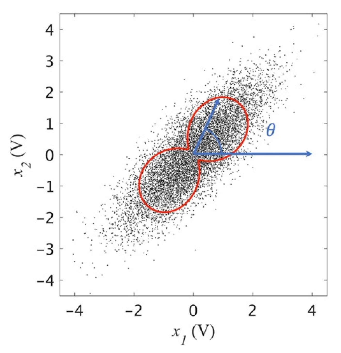
  • Gaussianity and kurtosis of the signal: Most BSS methods, including the one discussed in Section 2, cannot separate the mixed signals when all the original signals are Gaussian signals. This is because the last step (ICA) is to rotate the mixed signal based on the change of kurtosis at different independent component directions. If both the stealth signal and noise have Gaussian distribution, or Gaussian-like signals (Equations (8) and (9)), the kurtosis is equal to 3 at all the directions, and the mixed signals cannot be rotated to separate the mixed signal. Therefore, the system is immune to BSS attacks when both the stealth signal and noise are Gaussian signals.
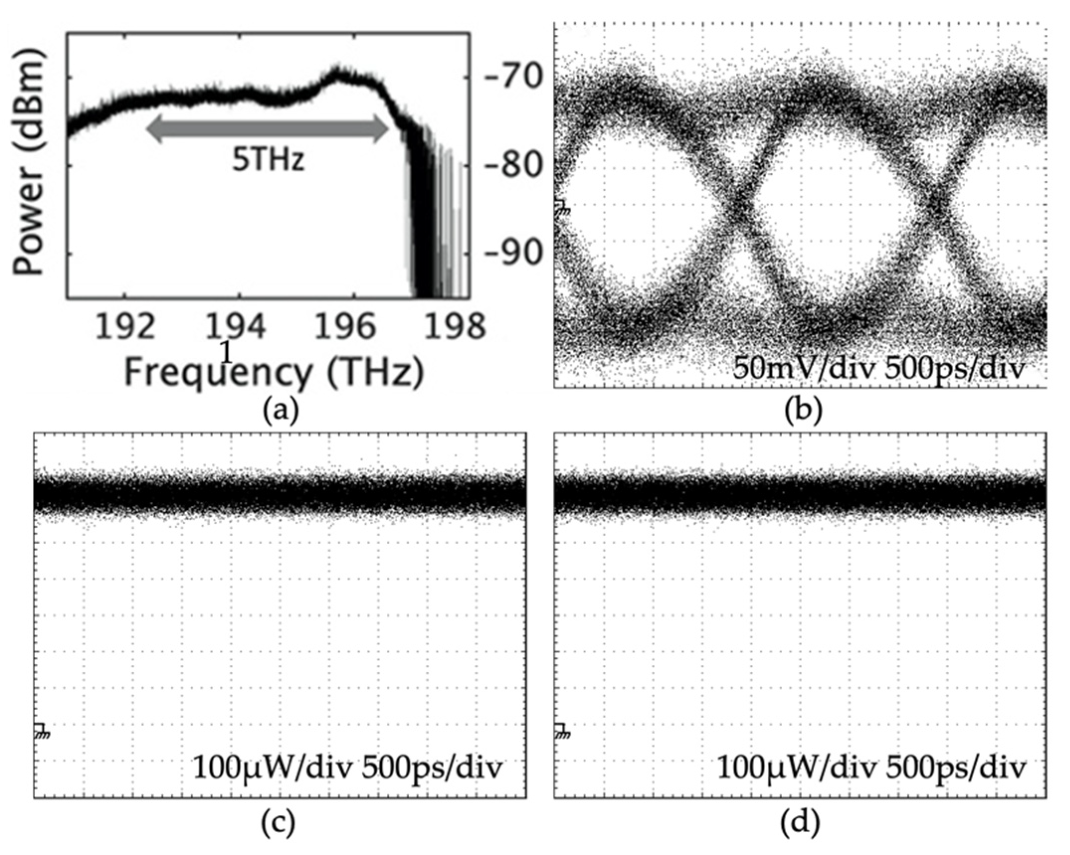
  • Bandwidth of the signal: The requirement of a Gaussian signal is a strict restriction to the stealth signal since most digital signals are not Gaussian signals. Another means of defending against the BSS attack is to expend the bandwidth of the noise signal. The sampling time must be short enough, so the sampled signal is not a time average of the mixed signal. By using the mode-locked laser to improve the sampling time, mixed signals with a bandwidth of up to 50 GHz can be properly sampled. Bandwidth of 50 GHz is an ultra-wideband for interference management, while for stealth communication with noise applied intentionally, bandwidth beyond 50 GHz can be deployed. Experimental results have demonstrated using noise bandwidth of 150 GHz–5000 GHz to hide signals.
  • Linear and nonlinear operation: For interference management, the signals are mixed with linear functions. To hide signals in noise, both linear and nonlinear operations can be applied to mix the signals and noise. Experimental results show that with nonlinear operations, the SOI cannot be identified by the statistical properties of the mixed signals, which means the stealth system with a nonlinear mixing function can effectively defend the BSS attack.

3.3. Future Perspectives

3.3.1. Wireless Stealth Communication and Hybrid with Interference Management

The related work has demonstrated the stealth system in fiber links and free space optical communication systems. One of the future perspective stealth methods is photonic stealth communication with RF signal carriers for wireless communications. Since the security of the system relies on the bandwidth of the noise, future stealth communication systems should be tested with RF carrier frequencies beyond 25 GHz, which provides 10 GHz to 100 GHz bandwidth. The interferometer can be scaled to the wireless system (Figure 7). The RF signal is modulated on optical carriers to generate long-range and frequency-independent delays (D1 and D2 in Figure 7). Compared with the optical link, the RF version has the advantage of using MIMO transmitter and receiver to separate the reference signal cos [ ω c + n ( t ) ] with cos [ ω c + s ( t ) + n ( t ) ] , which removes the combination in Figure 5 and improves the signal to noise ratio. The separation is performed with BSS methods described in Section 2.1. The BSS process does not affect the security of the system, since it only separates the linear combination of cos [ ω c + n ( t ) ] and cos [ ω c + s ( t ) + n ( t ) ] , and does not separate the nonlinear combination of signal and noise. The noise can only be cancelled when physical keys, D1 and D2 are matched.

3.3.2. Coexistence of Stealth Channel and Public Channel

Another future perspective for stealth communication is to hide the stealth channel in the public channel with noise and recovering the stealth signal by the hybrid system. Compared with the digital ways of separation, the hybrid system has two major advantages: (1) The privacy of the public channel is protected. In traditional digital-based method, to separate the stealth channel from the public channel requires the information from the public channel to be digitized at the stealth receiver. Since public channel has a higher data rate than the stealth channel. The digitization process not only introduces a considerate amount of workload to the stealth receiver but also expose the public channel data. By using the analog system discussed in Section 3.2, the stealth signal is separated from the public channel by the analog method without knowing the information from the public channel. (2) With the hybrid system, the public channel distributes keys in a secure way between the stealth transmitter and the receiver. Traditional methods share the public keys for the stealth channel with a public channel. Since the public channel is not protected, sharing digital keys directly with public channel exposes the existence of the stealth channel. Instead of sending the digital keys with unprotected public channels, the public keys are distributed through the statistical information of the public channels. The statistical information of public channels always exists whether the stealth channel is turned on or off.
The statistical information is measured by the hybrid system discussed in Section 2 with under-sampled signals. The public keys are shared between the stealth receiver and the stealth transmitter. By using Rivest–Shamir–Adleman (RSA) algorithm, the stealth transmitter uses the public key to encrypt the stealth signal, and the stealth use private to decrypt the stealth signal.
This perspective recovers the stealth signal by using hybrid photonic signal processing and blind source separation methods. The photonic method can mix and separate signal with hundreds of GHz to THz bandwidth in real-time, which is far beyond the ADC limit and enable completely stealth transmission. The blind source separation device measures the under-sampled pattern of the mixed signal, which is the public key of the stealth channel, and with the private keys, the signal can be recovered. The private key has two components (Figure 8): (1) the trained parameters of the neuron network for edge device; (2) the physical parameter of the photonic system. An eavesdropper can also measure the statistical pattern of the public channel and find out the public key; however, without the private key, the existence of the signal cannot be detected.

4. Conclusions

In this review, the two core elements of wideband mixed signal separation based on photonic signal processing, which are interference management and stealth communication, are summarized. We show principles, experimental results for interference management for photonic stealth communication systems. Additionally, the challenges and future perspectives for hybrid radio frequency and photonic communication systems are explored. The challenges and related work of interference management are proven. Using under-sampled signals to perform principal component analysis (PCA) and independent component analysis (ICA) is explained and theoretically proven. The experimental setup of the photonic interference circuit for stealth communication is demonstrated and the principle of using the physical properties of the wide bandwidth of optical carriers to hide the signal of interest is explained and experimentally demonstrated to transmit 500 Mbps–5 Gbps binary signals in optical noise with bandwidth up to 5000 GHz. The feasibility and future perspectives of the seamless integration of analog signal processing with photonic circuits and digitally processing the statistical patterns of the under-sampled signals is discussed.

Author Contributions

Conceptualization, B.W.; investigation, B.W.; writing—original draft preparation, B.W.; writing—review and editing, B.W., Y.Q. and T.S. All authors have read and agreed to the published version of the manuscript.

Funding

This research received no external funding.

Conflicts of Interest

The authors declare no conflict of interest.

Appendix A

Table A1. Table of symbols and abbreviations.
SymbolDefinition
SOISignal of interest
BSSBlind source separation
RFRadio frequency
CDMACode-division multiple access
OFDMOrthogonal frequency-division multiplexing
PCAPrincipal component analysis
ICAIndependent component analysis
ASEAmplified spontaneous emission
X Received mixed signal
A Mixing matrix
S Source signal
x 1 ,   x 2 Signal received by Receiver 1, 2
a m n Channel coefficient
x P C A Added weights for PCA to mixed signal
E ( x P C A 2 ) The   expectation   or   time   average   of   x P C A 2 for PCA
U Rotation   matrix   by   angle   θ 0 for PCA
Σ Rectangular diagonal matrix for PCA
V Rotation   matrix   by   angle   ϕ 0 for ICA
x I C A Added weights for ICA to mixed signal
( x I C A 4 ) 4th order moments (kurtosis) for ICA
Table A2. Previous works.
Reference Paper(s)Topic
[12,14,17]Photonic Circuit for Interference Management
[20,21,22]Digital System for Interference Management
[72,73,75]Stealth Communication

References

  1. Hossain, E.; Rasti, M.; Tabassum, H.; Abdelnasser, A. Evolution toward 5G multi-tier cellular wireless networks: An interference management perspective. IEEE Wirel. Commun. 2014, 21, 3. [Google Scholar] [CrossRef] [Green Version]
  2. Bloch, M.R. Covert Communication over Noisy Channels: A Resolvability Perspective. IEEE Trans. Inf. Theory. 2016, 62, 5. [Google Scholar] [CrossRef] [Green Version]
  3. Wu, B.; Wang, Z.; Tian, Y.; Fok, M.; Shastri, B.; Kanoff, D.; Prucnal, P.R. Optical steganography based on amplified spontaneous emission noise. Opt. Express 2013, 21, 2065–2071. [Google Scholar] [CrossRef] [PubMed] [Green Version]
  4. Wu, B.; Shastri, B.; Mittal, P.; Tait, A.N.; Prucnal, P.R. Optical Signal Processing and Stealth Transmission for Privacy. IEEE J. Sel. Top. Signal Process. 2015, 9, 1185–1194. [Google Scholar]
  5. Akhgar, B.; Arabnia, H.R. Secure Communication in Fiber-Optic Networks; Elsevier Inc.: Amsterdam, The Netherlands, 2013. [Google Scholar]
  6. Capmany, J.; Mora, J.; Gasulla, I.; Sancho, J.; Lloret, J.; Sales, S. Microwave photonic signal processing. J. Light. Technol. 2013, 4, 571–586. [Google Scholar] [CrossRef]
  7. Wu, B.; Chang, M.P.; Shastri, B.J.; Tait, A.N.; Prucnal, P.R. Optical steganography based on amplified spontaneous. OSA 2013, 21, 250–251. [Google Scholar]
  8. Giuliano, R.; Mazzenga, F. On the coexistence of power-controlled ultrawide-band systems with UMTS, GPS, DCS1800, and fixed wireless systems. IEEE Trans. Veh. Technol. 2015, 54, 1. [Google Scholar] [CrossRef]
  9. Guidotti, A.; Guiducci, D.; Barbiroli, M.; Carciofi, C.; Grazioso, P.; Riva, G. Coexistence and Mutual Interference between Mobile and Broadcasting Systems. In Proceedings of the IEEE Transactions on Vehicular Technology, Budapest, Hungary, 15–18 May 2011; pp. 1–15. [Google Scholar]
  10. Bash, B.A.; Goeckel, D.; Towsley, D.; Guha, S. Hiding information in noise: Fundamental limits of covert wireless communication. IEEE Commun. 2015, 53, 12. [Google Scholar] [CrossRef] [Green Version]
  11. Kohno, R.; Meidan, R.; Milstein, L.B. Spread Spectrum Access Methods for Wireless Communications. IEEE Commun. Mag. 1995, 33, 1. [Google Scholar] [CrossRef] [Green Version]
  12. Zhou, M.; van der Veen, A.J. Blind separation of partially overlapping data packets. Digit. Signal Process. A Rev. J. 2017, 68, 154–166. [Google Scholar] [CrossRef]
  13. Hajisami, A.; Pompili, D. Cloud-BSS: Joint intra- and inter-Cluster interference cancellation in uplink 5G cellular networks. Comput. Netw. 2018, 147, 180–190. [Google Scholar] [CrossRef]
  14. Yu, J.; Li, J.; Sun, B.; Chen, J.; Li, C. Multiclass radio frequency interference detection and suppression for SAR based on the single shot multibox detector. Sensors 2018, 18, 4034. [Google Scholar] [CrossRef] [Green Version]
  15. Luo, Z.; Li, C.; Zhu, L. Full-Duplex Cognitive Radio Using Guided Independent Component Analysis and Cumulant Criterion. IEEE Access 2019, 7, 27065–27074. [Google Scholar] [CrossRef]
  16. Boya, C.; Rojas-Moreno, M.V.; Ruiz-Llata, M.; Robles, G. Location of partial discharges sources by means of blind source separation of UHF signals. IEEE Trans. Dielectr. Electr. Insul. 2015, 22, 4. [Google Scholar] [CrossRef]
  17. Fabrizio, G.; Farina, A. Blind source separation with the generalised estimation of multipath signals algorithm. IET Radar Sonar Navig. 2014, 8, 1255–1266. [Google Scholar] [CrossRef]
  18. Sun, S.; Rappaport, T.S.; Heath, R.W.; Nix, A.; Rangan, S. MIMO for millimeter-wave wireless communications: Beamforming, spatial multiplexing, or both? IEEE Commun. Mag. 2014, 12, 110–121. [Google Scholar] [CrossRef]
  19. Jensen, M.A.; Wallace, J.W. A review of antennas and propagation for MIMO wireless communications. IEEE Trans. Antennas Propag. 2004, 52, 2810–2824. [Google Scholar] [CrossRef] [Green Version]
  20. Vook, F.W.; Ghosh, A.; Thomas, T.A. MIMO and Beamforming Solutions for 5G Technology. In Proceedings of the IEEE MTT-S International Microwave Symposium Digest, Tampa, FL, USA, 1–6 June 2014; pp. 1–4. [Google Scholar]
  21. Dean, T.R.; Wootters, M.; Goldsmith, A.J. Blind Joint MIMO Channel Estimation and Decoding. IEEE Trans. Inf. Theory 2019, 65, 4. [Google Scholar] [CrossRef]
  22. Tait, A.N.; Ma, P.; Ferreira de Lima, T.; Blow, E.; Chang, M.; Nahmias, M.; Shastri, B.; Prucnal, P. Demonstration of Multivariate Photonics: Blind Dimensionality Reduction With Integrated Photonics. J. Lightwave Technol. 2019, 37, 5996–6006. [Google Scholar] [CrossRef]
  23. Björnson, E.; Sanguinetti, L.; Wymeersch, H.; Hoydis, J.; Marzetta, T.L. Massive MIMO is a reality—What is next? Five promising research directions for antenna arrays. Digit. Signal Process. Rev. J. 2019, 94, 3–20. [Google Scholar] [CrossRef]
  24. Liu, B.; Dai, W.; Peng, W.; Meng, X. Spatiotemporal analysis of GPS time series in vertical direction using independent component analysis. Earth Planets Space 2015, 67, 1. [Google Scholar] [CrossRef] [Green Version]
  25. Gualandi, A.; Serpelloni, E.; Belardinelli, M.E. Blind source separation problem in GPS time series. J. Geod. 2016, 90, 4. [Google Scholar] [CrossRef]
  26. Kharbech, S.; Dayoub, I.; Simon, E.; Zwingelstein-Colin, M. Blind digital modulation detector for MIMO systems over high-speed railway channels. Lect. Notes Comput. Sci. 2013, 7865, 232–241. [Google Scholar]
  27. Lü, X.; Zhang, H.; Liu, Z.; Sun, Z.; Liu, P. Research on Co-channel Base Station Interference Suppression Method of Passive Radar Based on LTE Signal. J. Electron. Inf. Technol. 2019, 41, 9. [Google Scholar]
  28. Delfosse, N.; Loubaton, P. Adaptive blind separation of independent sources: A deflation approach. Signal Process. 1995, 45, 1. [Google Scholar] [CrossRef]
  29. Bach, F.R.; Jordan, M.I. Kernel independent component analysis. J. Mach. Learn. Res. 2003, 3, 1. [Google Scholar]
  30. Comon, P.; Jutten, C. Handbook of Blind Source Separation; Academic Press: Cambirgde, MA, USA, 2010. [Google Scholar]
  31. Cardoso, J.F. Blind signal separation: Statistical principles. Proc. IEEE 1998, 86, 10. [Google Scholar] [CrossRef] [Green Version]
  32. Agiwal, M.; Roy, A.; Saxena, N. Next generation 5G wireless networks: A comprehensive survey. IEEE Commun. Surv. Tutor. 2016, 18, 3. [Google Scholar] [CrossRef]
  33. Amjad, M.; Musavian, L.; Rehmani, M.H. Effective Capacity in Wireless Networks: A Comprehensive Survey. IEEE Commun. Surv. Tutor. 2019, 21, 4. [Google Scholar] [CrossRef] [Green Version]
  34. Tajvidy, A. Channel capacity model in urban areas at 20–70 GHz for 5G systems. Electromagnetics 2020, 40, 1. [Google Scholar] [CrossRef]
  35. Ban, Y.L.; Li, C.; Sim, C.Y.D.; Wu, G.; Wong, K.L. 4G/5G Multiple Antennas for Future Multi-Mode Smartphone Applications. IEEE Access 2016, 4, 2981–2988. [Google Scholar] [CrossRef]
  36. Hong, S.; Brand, J.; Choi, J., II; Jain, M.; Mehlman, J.; Katti, S.; Levis, P. Applications of self-interference cancellation in 5G and beyond. IEEE Commun. Mag. 2014, 52, 2. [Google Scholar]
  37. Balakrishnan, J.; Batra, A.; Dabak, A. A Multi-Band OFDM System for UWB Communication. In Proceedings of the IEEE Conference on Ultra Wideband Systems and Technologies, Reston, VA, USA, 16–19 November 2003; pp. 354–358. [Google Scholar]
  38. Wang, F.; Yang, A.H.; Kimball, D.F.; Larson, L.E.; Asbeck, P.M. Design of wide-bandwidth envelope-tracking power amplifiers for OFDM applications. IEEE Trans. Microw. Theory Tech. 2005, 53, 4. [Google Scholar]
  39. Ma, L.; Jiang, W.; Xiang, H. Parameter estimation based on factor graph in wide-band OFDM systems. IET Commun. 2019, 13, 12. [Google Scholar] [CrossRef]
  40. Bourgeois, P.; Imaike, T.; Goavec-Merou, G.; Rubiola, E. Noise in High-Speed Digital-to-Analog Converters. In Proceedings of the IEEE International Frequency Control Symposium and European Frequency and Time Forum, Denver, CO, USA, 12–16 April 2015; pp. 672–675. [Google Scholar]
  41. Walden, R.H. Analog-to-digital converter survey and analysis. IEEE J. Sel. Areas Commun. 1999, 17, 539–550. [Google Scholar] [CrossRef] [Green Version]
  42. Larsson, E.G.; Edfors, O.; Tufvesson, F.; Marzetta, T.L. Massive MIMO for next generation wireless systems. IEEE Commun. Mag. 2014, 52, 2. [Google Scholar] [CrossRef] [Green Version]
  43. Wu, B.; Chang, M.P.; Shastri, B.J.; Wang, Z.; Prucnal, P.R. Analog noise protected optical encryption with two-dimensional key space. Opt. Express 2014, 22, 14568. [Google Scholar] [CrossRef]
  44. Yang, Q.; Wu, B. Photonic Interference Cancellation with Free-Space Optical Link for Cellular Networks. In Frontiers in Optics; Optical Society of America: Washington, DC, USA, 2020; p. FTh5E.2. [Google Scholar]
  45. Yang, Q.; Wu, B. Radio Frequency Spectrum Control Based on Wideband Jamming and Photonic Jamming Cancellation. In Laser Science; Optical Society of America: Washington, DC, USA, 2019; p. JW3A.65. [Google Scholar]
  46. Wu, B.; Chang, M.P.; Wang, Z.; Shastri, B.J.; Prucnal, P.R. Optical Encryption based on Cancellation of Analog Noise. In Proceedings of the CLEO—Laser Science to Photonic Applications, San Jose, CA, USA, 8–13 June 2014; p. AW3P. [Google Scholar]
  47. Chang, M.P.; Wang, N.; Wu, B.; Prucnal, P.R. A Simultaneous Variable Optical Weight and Delay in a Semiconductor Optical Amplifier for Microwave Photonics. J. Light. Technol. 2015, 33, 2120–2126. [Google Scholar] [CrossRef]
  48. Chang, M.P.; Lee, C.L.; Wu, B.; Prucnal, P.R. Adaptive optical self-interference cancellation using a semiconductor optical amplifier. IEEE Photonics Technol. Lett. 2015, 27, 1018–1021. [Google Scholar] [CrossRef]
  49. Tait, A.N.; Nahmias, M.A.; Shastri, B.J.; Chang, M.P.; Wu, A.X.; Zhou, E.; Blow, E.C.; Ferreira de Lima, T.; Wu, B.; Prucnal, P.R. Balanced WDM weight banks for analog optical processing and networking in silicon. IEEE Summer Top. Meet. Ser. 2015, 3, 21–22. [Google Scholar]
  50. Shi, T.; Veneziano, N.; Qi, Y.; Chen, H.; Wu, B. Photonic Weight Banks based on Multimode Fiber for Neuromorphic Networks. In Frontiers in Optics; Optical Society of America: Washington, DC, USA, 2020; p. FM7D.2. [Google Scholar]
  51. Hyvärinen, A.; Oja, E. Independent component analysis: Algorithms and applications. Neural Netw. 2000, 13, 411–430. [Google Scholar] [CrossRef] [Green Version]
  52. Tait, A.N.; de Lima, T.F.; Ma, P.Y.; Chang, M.P.; Nahmias, M.A.; Shastri, B.J.; Mittal, P.; Prucnal, P.R. Blind Source Separation in the Physical Layer. In Proceedings of the 52nd Annual Conference on Information Sciences and Systems (CISS), Princeton, NJ, USA, 21–23 March 2018; pp. 1–6. [Google Scholar]
  53. Shi, T.; Qi, Y.; Zhang, W.; Prucnal, P.; Li, J.; Wu, B. Wideband photonic blind source separation with optical pulse sampling. Opt. Express 2021, 29, 23. [Google Scholar]
  54. Belsley, D.A.; Kuh, E.; Welsch, R.E. Chapter the Condition Number. In Regression Diagnostics: Identifying Influential Data and Sources of Collinearity; John Wiley & Sons: Hoboken, NJ, USA, 2004. [Google Scholar]
  55. Liu, H.; Cheung, Y.M. A New Blind Separation Approach to Ill-Condition Mixed Sources. In Proceedings of the IEEE International Workshop on VLSI Design and Video Technology, Suzhou, China, 28–30 May 2005; pp. 133–136. [Google Scholar]
  56. Lin, C.H.; Bioucas Dias, J.M. New Theory for Unmixing ILL-Conditioned Hyperspectral Mixtures. In Proceedings of the IEEE Sensor Array and Multichannel Signal Processing Workshop, Sheffield, UK, 8–11 July 2018; pp. 430–434. [Google Scholar]
  57. Perotin, L.; Serizel, R.; Vincent, E.; Guérin, A. CRNN-based multiple DoA estimation using Ambisonics acoustic intensity features. IEEE Int. Conf. Acoust. Speech Signal Process. Proc. 2018, 12, 4. [Google Scholar] [CrossRef] [Green Version]
  58. Liu, H.L. Blind separation of ill-condition mixed sources based on generalized eigenvalue. Tien Tzu Hsueh Pao/Acta Electron. Sin. 2006, 34, 11. [Google Scholar]
  59. Zhou, G.; Xie, S.; Yang, Z.; Zhang, J. Nonorthogonal approximate joint diagonalization with well-conditioned diagonalizers. IEEE Trans. Neural Netw. 2009, 20, 11. [Google Scholar]
  60. Lee, I.; Jang, G.J. Independent vector analysis based on overlapped cliques of variable width for frequency-domain blind signal separation. EURASIP J. Adv. Signal Process. 2012, 1, 113. [Google Scholar] [CrossRef] [Green Version]
  61. Yang, S.; Li, J.; He, B. A Novel Interference Suppression Method in Spread Spectrum Communication based on Blind Source Separation. In Proceedings of the IEEE International Conference on Cognitive Computing, San Francisco, CA, USA, 2–7 July 2018. [Google Scholar]
  62. Kang, C.Y. Directional interference supression based on blind source separation with beamforming. Zidonghua Xuebao/Acta Autom. Sin. 2014, 40, 5. [Google Scholar]
  63. Li, C.; Zhu, L.; Xie, A.; Luo, Z. A Novel Blind Source Separation Algorithm and Performance Analysis of Weak Signal against Strong Interference in Passive Radar Systems. Int. J. Antennas Propag. 2016, 2016, 6203972. [Google Scholar] [CrossRef] [Green Version]
  64. Mitra, U.; Poor, H.V. Neural Network Techniques for Adaptive Multiuser Demodulation. IEEE J. Sel. Areas Commun. 1994, 12, 9. [Google Scholar] [CrossRef] [Green Version]
  65. Kang, C.; Zhang, X.; Fan, W.; Li, J. Suppressing directional interference combining frequency domain blind source separation with beamforming. Acta Acust. 2014, 39, 5. [Google Scholar]
  66. Baan, W.A.; Fridman, P.A.; Millenaar, R.P. Radio Frequency Interference Mitigation at the Westerbork Synthesis Radio Telescope: Algorithms, Test Observations, and System Implementation. Astron. J. 2004, 128, 2. [Google Scholar] [CrossRef] [Green Version]
  67. Akeret, J.; Chang, C.; Lucchi, A.; Refregier, A. Radio frequency interference mitigation using deep convolutional neural networks. Astron. Comput. 2017, 18, 35–39. [Google Scholar] [CrossRef] [Green Version]
  68. Leshem, A.; van der Veen, A.; Boonstra, A. Multichannel Interference Mitigation Techniques in Radio Astronomy. Astrophys. J. Suppl. Ser. 2000, 131, 1. [Google Scholar] [CrossRef]
  69. Umar, R.; Abidin, Z.Z.; Ibrahim, Z.A.; Hassan, M.S.R.; Rosli, Z.; Hamidi, Z.S. Population Density Effect on Radio Frequencies Interference (RFI) in Radio Astronomy. In AIP Conference Proceedings; American Institute of Physics: College Park, MA, USA, 2011; Volume 1454, p. 1. [Google Scholar]
  70. Umar, R.; Abidin, Z.Z.; Ibrahim, Z.A.; Rosli, Z.; Noorazlan, N. Selection of radio astronomical observation sites and its dependence on human generated RFI. Res. Astron. Astrophys. 2014, 14, 2. [Google Scholar] [CrossRef] [Green Version]
  71. Kish, L.B. Stealth communication: Zero-power classical communication, zero-quantum quantum communication and environmental-noise communication. Appl. Phys. Lett. 2005, 87, 23. [Google Scholar] [CrossRef] [Green Version]
  72. Sheikholeslami, A.; Ghaderi, M.; Towsley, D.; Bash, B.A.; Guha, S.; Goeckel, D. Multi-Hop Routing in Covert Wireless Networks. IEEE Trans. Wirel. Commun. 2018, 17, 3656–3669. [Google Scholar] [CrossRef]
  73. Soltani, R.; Goeckel, D.; Towsley, D.; Houmansadr, A. Fundamental Limits of Covert Packet Insertion. IEEE Trans. Commun. 2020, 68, 3401–3414. [Google Scholar] [CrossRef] [Green Version]
  74. Bloch, M.R.; Guha, S. Optimal covert communications using pulse-position modulation. In Proceedings of the IEEE International Symposium on Information Theory, Aachen, Germany, 25–30 June 2017; pp. 2825–2829. [Google Scholar]
  75. Wu, B.; Chang, M.P.; Shastri, B.J.; Ma, P.Y.; Prucnal, P.R. Dispersion Deployment and Compensation for Optical Steganography Based on Noise. IEEE Photonics Technol. Lett. 2016, 28, 421–424. [Google Scholar] [CrossRef]
  76. Wu, B.; Shastri, B.J.; Prucnal, P.R. System performance measurement and analysis of optical steganography based on noise. IEEE Photonics Technol. Lett. 2014, 26, 1920–1923. [Google Scholar] [CrossRef]
  77. Wu, B.; Wang, Z.; Shastri, B.J.; Chang, M.P.; Frost, N.A.; Prucnal, P.R. Temporal phase mask encrypted optical steganography carried by amplified spontaneous emission noise. Opt. Express 2014, 22, 954. [Google Scholar] [CrossRef]
  78. Wu, B.; Tait, A.N.; Chang, M.P.; Prucnal, P.R. WDM optical steganography based on amplified spontaneous emission noise. Opt. Lett. 2014, 39, 5925–5928. [Google Scholar] [CrossRef]
  79. Wu, B.; Huang, Y.K.; Zhang, S.; Shastri, B.J.; Prucnal, P.R. Long range secure key distribution over multiple amplified fiber spans based on environmental instabilities. CLEO 2016, 20, 4–5. [Google Scholar]
  80. Qi, Y.; Wu, B. Free-Space Optical Stealth Communication based on Wideband Noise. In Frontiers in Optics; Optical Society of America: Washington, DC, USA, 2018; p. FW5B.5. [Google Scholar]
  81. Wu, B.; Chang, M.P.; Shastri, B.J.; Tait, A.N.; Prucnal, P.R. Compact Optical Steganography based on Amplified Spontaneous Emission Noise. In Proceedings of the IEEE Photonics Conference, Reston, VA, USA, 4–8 October 2015; p. MG1.3. [Google Scholar]
  82. Wu, B.; Chang, M.P.; Caldwell, N.R.; Caldwell, M.E.; Prucnal, P.R. Amplifier Noise Based Optical Steganography with Coherent Detection. Coherent Phenom. 2015, 2, 13–18. [Google Scholar] [CrossRef]
  83. Wu, B.; Wang, Z.; Shastri, B.J.; Tian, Y.; Prucnal, P.R. Two Dimensional Encrypted Optical Steganography Based on Amplified Spontaneous Emission Noise. In CLEO Applications and Technology; Optical Society of America: Washington, DC, USA, 2013; Volume 21, p. AF1H.5. [Google Scholar]
  84. Wu, B.; Wang, Z.; Shastri, B.J.; Tian, Y.; Prucnal, P.R. Phase-Mask Covered Optical Steganography based on Amplified Spontaneous Emission Noise. In Proceedings of the IEEE Photonics Conference, Bellevue, WA, USA, 8–12 September 2013; pp. 137–138. [Google Scholar]
Figure 1. System model of BSS.
Telecom 02 00024 g001
Figure 2. Experimental setup of the photonic interference cancellation circuit. (AM: optical amplitude modulator, TD: tunable optical delay, TA: tunable optical attenuator, PD: photon detector).
Telecom 02 00024 g002
Figure 3. Mixed signal and second order moment.
Telecom 02 00024 g003
Figure 4. (a) 16QAM signal mixed with Gaussian noise; (b) histogram of the original mixed signal; (c) histogram of the under sampled signal.
Telecom 02 00024 g004
Figure 5. Schematic diagram of optical stealth communication [73].
Telecom 02 00024 g005
Figure 6. Experimental results of optical stealth communication: (a) spectrum of the stealth signal hidden in noise; (b) recovered stealth signal; (c) stealth signal hidden in noise without matching condition; (d) pure noise without stealth signal.
Telecom 02 00024 g006
Figure 7. Wireless stealth communication system.
Telecom 02 00024 g007
Figure 8. Public key generation from the under-sampled public channel data.
Telecom 02 00024 g008
Table 1. Photonic interference cancellation ratio at different bandwidths.
Interference BandwidthCancellation Ratio
200 MHz60 dB
1 GHz36 dB
3 GHz30 dB
Publisher’s Note: MDPI stays neutral with regard to jurisdictional claims in published maps and institutional affiliations.

