Abstract
The abundance of radio signals and their increasing number creates interferences on adjacent signals and sometimes, with co-channel communication. Jammers, which are operated by hackers or by military forces, are another source of smart and powerful interferences. This paper will discuss the effect of the continuous wave interference (CWI) on a radio communication receiver, specifically with the Digital Video Broadcasting for Satellite Second Generation (DVB-S2) communication standard. It investigates the general effect of the interference on a Quadrature Phase Shift Keying (QPSK) signal over each part of the DVB-S2 receiver. It also focuses on the impact of the center frequency and power of the interference on the critical blocks of a DVB-S2 receiver. This study also tries to determine the deviation from the normal operation in the format of mathematical expressions and simulation results. Based on the obtained results, there is a vulnerability in the chain of the receiver’s blocks that allows a smart jammer to affect the device with low power interference. The notch filter is utilized as a solution to mitigate the interference. In addition, the effects of this technique on the system’s performance are studied. The simulation results show that there is a great improvement after CWI removal according to the Jamming to Signal Ratio (JSR), the Signal-to-Noise Ratio (SNR), and the Bit Error Rate (BER). In some cases, the JSR was reduced by 15 dB, the SNR was improved by 10 dB and BER also improved by 7 dB. However, the notch filter deletes some information from the original signal. This study introduces new ways to clarify the tradeoff between the amount of interference power reduction and removed bandwidth from the signal with notch filtering.
1. Introduction
The presence of radio frequency interference (RFI) on a radio signal can result from adjacent frequency band communications bleeding over the signal or co-channel communication [1]. This problem occurs more often because the communication bands are getting busier and closer to each other with the increase in demand for radio frequency (RF) communications. The need for ubiquitous signals for either internet, video broadcasting or private communication is increasing each year which makes interference a more frequent problem. Multiple devices have been designed to detect and remove interference in major broadband communications, e.g., Global Navigation Satellite System (GNSS) [2,3]. Interferences can also be generated by jammers, which are operated by hackers or by military forces to prevent RF communications. This type of jamming on RF communication bands can result in catastrophic events. A simple and cheap Software Defined Radio can easily generate CWI with high power and variable center frequency. Interference can have disastrous consequences, especially on navigation, since it can cause a complete or partial signal loss. Multiple devices using navigation for guidance can be affected, including cars, airplanes, satellites, etc. [2,4]. The effects vary between error in positioning measurements to the complete loss of navigation and this could have huge consequences such as a collision between two vehicles, which can result in loss of lives. On communication systems, however, the interference still has an important impact and reduces the quality of the communication by increasing the BER and packet loss [5].
For multiple communication protocols, interference mitigation techniques were developed and implemented since the effect of the interference is important on the system [6]. For example, the Spatial MMSE (Minimal Mean Square Error) and the Spatial MMSE-SIC (Successive Interference Cancellation) are methods used for multiple interference detection and cancellation. The idea is to identify how many interference signals are overlapping the desired information and attenuate them with filters in a cascade [7].
A CWI is an electromagnetic wave with constant frequency and amplitude such as a sine wave and it is very frequent in RF Spectrums. The primary focus is on a single narrow band CW interference, which looks like a sharp peak on a Power Spectral Density (PSD) diagram [8,9]. By analyzing the effect of the narrowband interference on the receiver, it will be easier to target the optimal position of the mitigation system in the structure to enhance the CWI detection and removal process. By knowing what parts of the receiver are more vulnerable to CWI, it is possible to improve the robustness of those parts to avoid possible accidents in the future.
In a simple telecommunication channel, there are more destructive effects than simply the Additive White Gaussian Noise (AWGN). The two most common effects are Doppler (or carrier shift) and variable time delay in path link [10]. To handle these negative channel effects and compensate for their drawbacks, a typical digital receiver utilizes different digital signal processing blocks. Fulfilling the task of digital reception, the structure of the physical layer of a digital receiver is divided into four important parts. The first part is the signal constellation which is the data demodulated by the receiver [11]. The second part is the symbol timing recovery which fulfills the correct sampling time duty [12]. Symbol timing is crucial in order to correctly extract the transmitted symbols with maximum energy from the upsampled signal. The third part is the frame synchronization which allows the boundaries of packets to be detected and the data extraction for decoding [13]. The final part is the carrier frequency recovery that allows a smooth adjustment of the observed carrier frequency whose movement is caused by the Doppler effect and carrier frequency shift [14]. The CWI has an impact on all those sections, and they will be studied in detail to determine the exact effect on the communication performances. CWI has two important characteristics: power and center frequency. At first, it seems that the only important parameter is the power, but a smart jammer can adjust the center frequency and completely stop the receiver even with a low power interference. Therefore, this research not only tries to clarify the degree of negative impacts based on the input power of interference, but also to examine the sensitivity of each different block’s performance based on the center frequency value and, potentially, avoid a dangerous low power smart attack [2].
In order to remove the CWI and protect the system against the narrowband attacks, this research focuses on the use of a novel implementation of an adaptive notch filter [15]. Quality of Service (QoS) must be preserved in different situations. However, for any interference mitigation, the removal of the interference cannot be perfect, which means that the mitigation process will affect the useful signal. First, the effect of a notch filter on the signal without any interference is studied to discover how much information is lost from the original signal based on the bandwidth of a notch filter. Afterwards, the impact of the notch filter on a signal with CWI is investigated. These results will be compared for different r values which is a parameter that controls the notch filter bandwidth. QoS enhancement and interference power reduction after filtering are carefully measured in terms of three parameters: Signal to Noise Ratio (SNR), Jamming to Signal Ratio (JSR) and Bit Error Rate (BER).
This paper investigates the effect of CWI on each section of a DVB-S2 [10] receiver and its removal with an adaptive notch filter. The DVB-S2 standard was released in 2005 and then became one of the most widely used video broadcasting standards. In February 2014, it was followed by the DVB-S2X, which allowed a faster communication protocol than its predecessor. Nowadays, DVB-S2 is still widely used and faces some problems with the increasing amount of interferences. For this study, the DVB-S2 standard was used because of its outstanding structure to handle the worst channel situation. The standard DVB-S2X, although more recent, is founded on the same core components as the original DVB-S2 standard. That means that it is sharing the same digital signal processing blocks as DVB-S2. This standard also represents relatively well the reception structure of most other telecommunication standards. All selected algorithms are those that are highly recommended in the user manual and structure of the DVB-S2 standard and based on those algorithms, the DVB-S2 standard can achieve performance close to the Shannon–Hartley limit [10].
2. Literature Review and Related Works
Multiple interference mitigation techniques were developed for broadband radio communication [7,8,15]. Most communication protocols are shielded against adjacent communication interference. Since the rise of co-channel communications, either unintentional or intentional interferences are still a possible problem for this type of communication. An interference mitigation research in 2016 was conducted to identify the effects of wideband, narrowband, and radar interferences on a standard satellite communication (SATCOM) protocol [16].
A similar study was conducted to analyze the interference mitigation methods for GNSS broadband communications [17]. To remove the interference after the detection, a discrete notch filter is used to adapt in real-time to the center frequency and to the amplitude of the interference. The use of finite impulse response filters (FIR) [18] and infinite impulse response filters (IIR) are the most common for interference removal of discrete communication signals [15]. Compared with FIR filters, IIR filters have a simpler structure and faster convergence time.
More recently, a study was carried out on the effects of the CWI center frequency on an orthogonal frequency division multiplex (OFDM) signal, which is used in modern wireless devices. This digitally modulated signal is vulnerable to CWI, so it is very important to mitigate its effects. Not only that, but a small variation in the CWI center frequency could cause a huge rise in the BER of this system [19].
Research [17,20] tries to utilize a notch filter as a computationally efficient solution for protecting the GNSS system against narrowband attacks. One of the most important shortcomings of the notch filtering literature is the usage of a second-order or bi-polar notch filter. This type of notch has two symmetric gaps and can be applied to a real input signal. This means that two bands of the input signal are removed by the filter. Telecommunication signals have “in-phase” and “quadrature” components that make the receiver able to work properly with both components as a complex number. Working with complex numbers allows the system to use complex filters. Compressed digital communication signal like DVB-S2, carries significant information in a narrow frequency band. This paper tries to utilize a first-order notch filter that has only one gap to preserve the quality of service as much as possible.
In [18], a linear multistage Wiener filter is utilized to remove narrowband interference in a high data rate direct-sequence ultra-wideband (DS-UWB) system. The research benefits from the second-order statistics of the received signal for faster filter coefficient convergence. Compared to a simple IIR notch filter, this filter has more complexity that increases directly with the number of utilized filter taps. For a notch filter, there are two important parameters: center frequency of the notch and its bandwidth. Those parameters can simply be adjusted as two numbers by the external detector. That makes the notch filter suitable to remove a narrowband interference with fast hopping center frequency and makes it possible to design the detector completely independently of the notch filter based on any desired statistical or non-statistical algorithms.
Studies [21,22] are great examples of trying to protect a digital communication standard against narrowband interference. The author compares the performance of null-subcarriers reservation (NSR) and an adaptive notch filter (ANF) for narrowband interference suppression utilized in intensity modulation and direct detection (IM/DD) system. This article implemented all the blockchain of the DMT standard and utilizes quadrature phase-shift keying (QPSK) symbols for data modulation. The author uses BER curves to compare the obtained system performance with two different algorithms. Based on this research, ANF outperforms the NSR scheme in narrowband interference cancellation. However, this study does not investigate the system behavior with different interference power levels. There is a tradeoff between the remaining interference power and removed data from the spectrum of the desired signal. When the interference power is low, the important parameter is the removed frequency band from the desired spectrum. While for powerful interference, residual interference is more important and can paralyze special blocks in the chain block of the receiver. Compared to [22], the current study tries to introduce the “remaining interference power” after filtering. In the first section of this current study, the sensitivity of each block of a digital receiver to interference power is carefully analyzed and the critical threshold that stops that block from functioning correctly is displayed based on the simulations. Then, in another section, the residual interference power based on the notch filter bandwidth is displayed. For utilizing a notch filter, with the knowledge of the system sensitivity in critical, the user is able to discover which gap bandwidth can guaranty that the residual power does not exceed the critical threshold.
In research [23], the author transfers digital data based on the IEEE 802.11 standard. Transferred data is then mixed with an AWGN channel and a CW interference with different power. The author describes the system degradation for different input interference power, based on the different BER curves. In the same way, obtained system performance is described based on the BER curves after filtering. Depictured BER curves in this study greatly expose the emergency of having an interference mitigation study for a typical digital receiver. However, adjusting the notch bandwidth adaptively based on JSR and the desired quality of service is missing from this paper. Another important point is that digital communication channels have more complicated effects that cause more system degradation in the presence of noise and add more blocks to the receiver chain.
Based on the discussion above, it can be seen that the literature about protecting a digital receiver against narrowband interference is still new. Following shortcoming subjects are open and highly demand more research and attention:
- Filter types and their effects on the quality of service: selected filter type directly determines the system limitation on interference mitigation. The amount of transmitted data that is removed by the filter gaps from the desired signal spectrum is an essential point for preserving the quality of service.
- Considered channel and its effect on the transmitted signal: it should be considered that communication channels almost contain more destructive effects than a simple AWGN channel. The most frequent and famous effects are Doppler (or carrier frequency shift) and variable time delay that exist even for wireless transmitter and receiver with a very short distance. These effects, in the presence of CWI, are more significant and can cause complete packet loss and full crash of the receiver. Caring about just a simple modulator is not sufficient.
- Typical digital receivers contain more blocks: to handle the real effects of a communication channel, a digital receiver must utilize different signal processing blocks to compensates for each effect individually. These blocks are sensitive to external interference and the amount of damage varies based on the interference parameters.
- Criteria to adjust the filter parameters: Prior to this study, most researches are focused on the effects of a narrow band interference on the received signal’s BER. Preserving QoS and also protecting all signal processing blocks require more consideration than the BER for filter adjustment.
- Considering the described shortcoming, the current study tries to fulfill the following study subjects:
- This study brings the first order notch filter in the chain of a digital receiver as a protector against narrowband interference and explains how it could be utilized beside other blocks.
- It considers more essential channel effects on the transmitted signal. As a drawback, the physical layer of the receiver must contain all required blocks for receiving data in real situations. The behavior of blocks is deeply analyzed in the presence of CWI. Deviation from the optimum work is explained in the term of packet loss or error from the correct detection. Thus, signal constellation vulnerability and system degradation caused by the other blocks are described mathematically and by simulation.
- It introduces more systematic parameters measurements for adjusting the r parameter and simple models are presented to clarify how to measure and define them. For example, the amount of residual interference after filtering is very important to know for digital receivers that have more sensitive blocks.
3. The Effects of Interference
This section shows the effects of CWI on the different stages of the communication using DVB-S2 standard. This effect is seen mostly in four stages: the signal constellation, the Symbol Time Recovery (STR) [24], the frame synchronization process [25] and the Carrier Frequency Recovery (CFR) [10]. These four steps can be found almost in all typical narrowband receivers. Figure 1 displays the main block diagram of the DVB-S2 receiver and its major components [10].
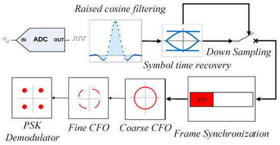
Figure 1.
Main blocks of DVB-S2 receiver.
Symbol time recovery (STR) adjusts the correct time of downsampling, which allows selected samples to have the maximum energy and a correct position at the center of the eye diagram. DVB-S2 standard uses the Gardner algorithm [24] to perform the STR process. After the STR block, the frame synchronization utilizes an appropriate correlator and searches the received frames, symbol by symbol, to find the start of the frame and the inserted physical layer (PL) header which contains information about the communication mode. The DVB-S2 transmitter inserts a unique word for the start of frame (SOF) at the beginning of a frame. When the correlator reaches the SOF position, a high peak is used as an indicator for correct detection [25]. After the frame synchronization, the receiver can detect the position of the pilots, thus, data aided Carrier-Frequency-Recovery (CFR) can be fulfilled. Usually, CFR is completed in two sequential steps. Both steps are based on inserted pilots. The first step is called coarse-carrier-recovery that removes a large part of the frequency offset. When the residual carrier offset is small enough, a more precise algorithm can be utilized to completely compensate for the carrier frequency offset. It should be mentioned that there is a mode, under good channel situation, that the transmitter turns off the pilots and the receiver must utilize blind algorithms to track the frequency offset and Doppler. Thus, the effect of CWI on the phase-locked loop (PLL) [26,27,28] based synchronizer is also investigated.
Besides mathematical analysis, in this research, all blocks are implemented in Matlab simulations to study the CWI effects on each block. In the simulation environment, we do not utilize the analog to digital converter and all numbers are in the discrete-time domain, thus, for simulation results sampling frequency can be ignored and all utilized frequencies are normalized in [−1 1] interval. CWI center frequencies are selected in a way that generates in-band interference with digital signal bandwidth (Figure 2).
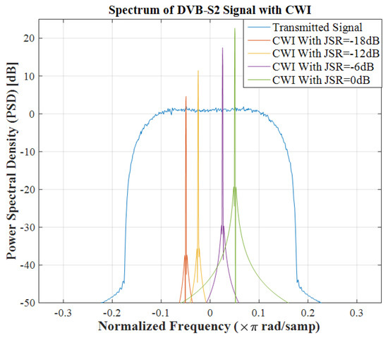
Figure 2.
Effect of CWI with different power on the spectrum of the signal.
3.1. Signal Constellation
A constellation diagram is a representation of a digitally modulated signal in a two-dimensional plane [29]. The general effect of CWI on the power spectral density, received SNR and signal constellation will be investigated in this section. Considering that transmitted signal S is the output of a QPSK signal constellation, then, with CWI, the received signal is:
where and are amplitude and center frequency of CWI, respectively. For simplicity, consider that the transmitted signal S has normalized power. Then the power of the two different parts are:
Then, Signal to Jamming Ratio (SJR) and Jamming to Signal Ratio parameters (JSR) are equal to:
Mathematically, it can be proven that adding a CWI would make the symbols circle around their constellation point. Since the transmitted signal is in the form , it can be transformed into complex cartesian form:
This means that the transmitted constellation points will be received as circles of radius around the original points. A Matlab simulation quickly verifies this result where a QPSK signal constellation is used. The results are visible in Figure 3.
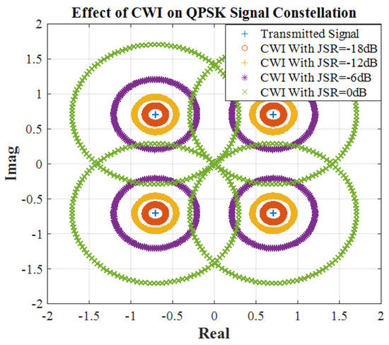
Figure 3.
Effect of CWI with different power on QPSK signal constellation.
Figure 2 and Figure 3 explain the effect of CWI with different JSR on both signal constellation and Power Spectral Density (PSD) of the signal. As can be seen in the frequency domain, the CWI appears as a peak at frequency. Stronger CWI will cause circles with a larger radius and a peak with a larger amplitude.
Now, consider that the channel also adds an AWGN channel [30] to the transmitted signal:
This part tries to calculate the Signal to Jamming Noise Ratio (SJNR) based on the noise and interference power. Figure 4 shows how AWGN and CWI affect the desired signal. In the channel, first the AWGN with variance is added to the signal with normalized power:

Figure 4.
Utilized scenario to measure the CWI effect on received SNR.
Calculating the signal to jamming noise ratio (SJNR), a new term of the total variance is defined as:
The equations above (6) and (7) explains received SNR reduction based on the CWI power. Figure 5 displays received SJNR based on SJR in different SNR. The simulation results completely match the obtained equations since both theoretical and simulation curves are perfectly overlapping. When the SJR is large enough, the SJNR curve converges to the SNR value. For larger SNRs, the system experiences more distortion than with a smaller SNR value. For example, in SJR = 15 dB, the curve of SNR = 20 dB decreases by 6 dB, however, the curve of SNR = 10 dB decrease just by 1 dB. Thus, the systems with higher QoS experience more distortion.
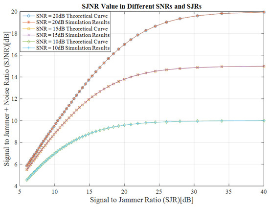
Figure 5.
Received SJNR based on the SJR value in different SNR.
Overall, this section covered the effect of the interference on the constellation diagram, QoS (in terms of received SNR) and PSD relative to its power. These results show that the CWI plays an important role in the overall SJNR value, especially for high values of SJR.
3.2. Symbol Timing Recovery
The STR block is an important part of the digital receivers. Gardner (GA) algorithms [24] is widely employed and well known for its great efficiency and high performance in acquisition procedures. It could be considered as the heart of the different types of receivers like DVB and time-division multiple access (TDMA) systems.
Figure 6 displays the structure of a Gardner symbol timing recovery [24]. The timing error is calculated in two parts: the real () and the imaginary (). The sum of those two is the total timing error (), and they are estimated as:
where x[nT] and y[nT] are the real and imaginary parts of the received samples and T is the sample duration. Although, when the system is affected by a CWI, its real and imaginary components are added to the samples.

Figure 6.
Structure of the symbol time recovery.
By substitution of (9) within (8), timing error under the jamming situation can be calculated as the following:
One can factorize and estimate the Final Error (FE) of the signal with a CWI:
Based on this estimation, it is clarified that the deviation from the correct timing error is proportional to the center frequency of a CW signal and its power.
From these results, CWI with higher frequencies has a larger effect on the STR stage than the ones with lower frequencies. DVB-S2 signal is a narrowband signal, which means that out of band interferences cannot affect its performance. For in-band CWI, multiplication of has maximum a value of 0.175. DVB-S2 is a narrowband signal, for in-band CWI, must be smaller than the maximum frequency of the transmitted signal. DVB-S2 signal benefits from the pulse shaping based on the raised cosine filtering with a maximum roll factor of β = 0.35. Thus, the maximum bandwidth of the signal is:
where Ts is the symbol duration and Nup is an upsampling factor. For in-band CWI, the maximum value of multiplication of can be calculated as the following equation:
Considering the maximum roll of factors and , multiplication of has a maximum value of 0.175. This criterion helps the Gardner algorithm to be naturally robust against the CWI. Figure 7 and Figure 8 show the estimated timing error with the Gardner algorithm while CWI is added to the input samples with different power and frequencies. In these figures, the input signal has a delay equal to half of the symbol period. Simulation results completely match the theoretical analysis. In Figure 7 and Figure 8, for the same power, CWI with higher frequency has more effect on timing error detection. It also confirms that the Gardner algorithm is robust against the CWI interference. As it can be seen, detected timing error converges to half of the symbol period even in the presence of powerful interference. Symbols are discovered correctly, however, because of the interference power, for each point of the signal constellation, symbols are distributed on the circle with a radius proper to the interference power.
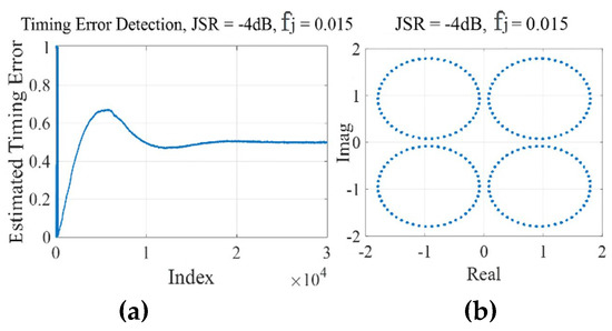
Figure 7.
STR of a QPSK with JSR = −4 dB, fj = 0.015 (×π rad/samp), CWI effect on (a) convergence curve and (b) output symbols.
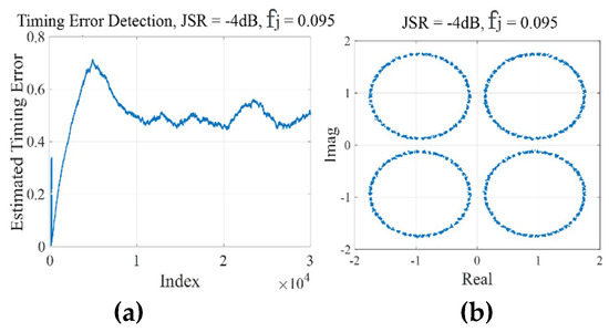
Figure 8.
STR of a QPSK with JSR = −4 dB, fj = 0.095 (×π rad/samp), CWI effect on (a) convergence curve and (b) output symbols.
3.3. Frame Synchronization
Frame synchronization is the process in which frame alignment bits are identified in incoming framed data, which allows the data to be extracted for decoding. In the DVB-S2 standard, the transmitter inserts 90 symbols at the beginning of a frame, called a physical layer (PL). Those symbols are not part of the data, but they can help to recognize the boundaries of a packet [6]. The start of frame (SOF) is 25 special symbols that the DVB-S2 transmitter inserts at the beginning of a frame. With those symbols, the receiver can find the start of the frame based on the correlation of the input frame with the SOF vector. Both the receiver and the transmitter are aware of the symbols in the header. The receiver correlates the input frame with the SOF symbols. After correlation, the position of SOF will appear in the detector as a peak and this peak shows the position of the frame start point. Figure 9 presents the structure of the frame in standard DVB.

Figure 9.
Structure of PL header in standard DVB-S2.
SOF has a special characteristic that allows the detector to utilize differential correlation. Deferential coefficients are obtained by multiplying each SOF symbol by the conjugate of the next SOF symbol [25]:
are differential coefficients of the SOF, SOFm, is the mth symbol of SOF in a packet and is the conjugate of that. Thus, inside the receiver, a correlator utilizes these 25 differential coefficients to obtain the start point of the frame [25]:
In Equation (15) above, shows the ith received symbols. ΛSOF is the result of the differential correlation of the input symbols and SOF symbols in the receiver. The position of the highest peak in ΛSOF displays the start of the frame. After correlation because of similarity, at the position of SOF, a large peak will be obtained. All steps of frame synchronization are implemented in Matlab and results are explained in Figure 10, Figure 11 and Figure 12. Figure 10 displays a typical response of the correlator. The Gardner algorithm downsamples the output of the analog to digital converter to the symbol. Thus, the timing delay is an integer multiplied by the symbol period. Because of satellite movement and random distance between the satellite and the receiver, the start point of the frame is a variable. In our simulation, we consider that there is a delay equal to the 300 of symbol time in the received packet. In this figure, received frames have a delay equal to the 300th symbol time, thus, a large peak is located at the 300th symbol. Distance between peak amplitude and correlation results with other samples determines the system’s robustness. The larger this distance is, the easier the SOF can be discovered. With a smaller distance, the amount of frame synchronization errors and packets lost will increase.
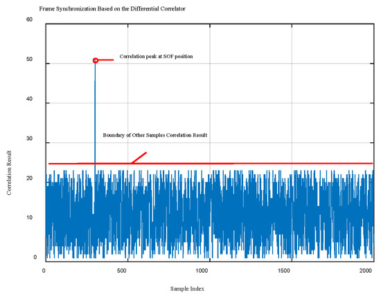
Figure 10.
Typical results of differential correlator for SOF peak detection.
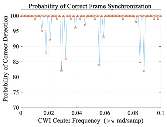
Figure 11.
Probability of successful frame synchronization depending on the CWI center frequency (JSR = −7 dB).
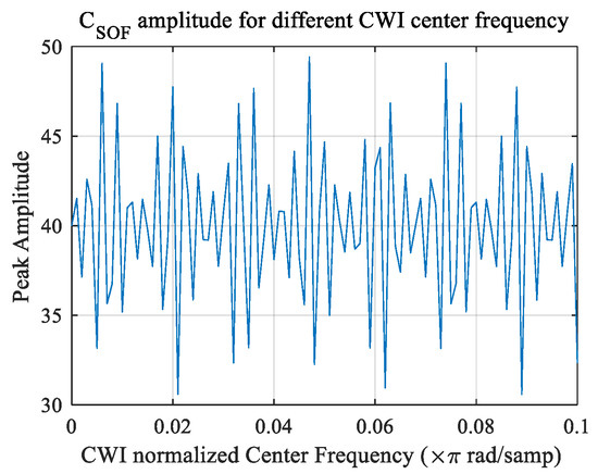
Figure 12.
Effect of CWI with different center frequency on the amplitude of indicator peak of synchronizer.
In the case of CWI, received samples are replaced by the following equation:
where n is the symbol index in the DVB-S2 frame and T is sampling time. By replacing this new sample in (16), the CWI effect on the frame synchronization process is cleared:
where and the term is the CWI effect. As it can be seen here, term is the CWI effect. Here, n is the symbol index in the DVB-S2 standard frame. CWI center frequency, , is multiplied by the symbol index and can go up to 32000. Multiplying CWI center frequency by a large number makes the response behavior sensitive to frequency and generates harmonics and periodic behavior with a small change in center frequency (Figure 12).
For frame synchronization, there are two states: 1-correct detection (or successful detection), if the start of frame detected is exactly equal to the position of the frame header, then the data can be retrieved from the packet. Two-error detection: any deviation, even one symbol from the exact position of the header causes the packet loss. If the number of Np packets is received, then successful frame synchronization is equal to the percentage of the packet that the receiver detected the header position:
where Nsuccess is the number of packets that the receiver successfully detected the position of the header in the packet. Because it is a two states event, the probability of error is equal to:
Figure 11 displays the probability of successful frame synchronization in the presence of CWI with JSR = −7 dB based on the simulation results. The block performance completely changes as the center frequency varies. With some center frequencies, the probability of correct detection can decrease to less than 85% which means 18% of packets are lost, which will cause large distortion in all the system (One example of minimum points can be seen between frequency 0.02 to 0.04). Thus, the frame synchronization process is vulnerable to CWI. Extra terms distort the differential correlation process in two ways:
- At some frequency, it damages the shape of the differential coefficients , therefore, peak amplitude, which indicates the start of the frame, decreases severely. Figure 12 represents the peak amplitude based on the CWI center frequency. Peak amplitude fluctuates between highly detectable amplitudes and critically low amplitudes for detection depending on the CWI center frequency as shown in Figure 12. Where the peak amplitude has its local minimums, correct detection probability is decreased as described in Figure 11.
- Another important factor for correct detection is the result of correlation with other samples. The structure of SOF in the DVB-S2 packet is in the way that, correlation with other samples is not large, thus, the start of the frame can be found by the receiver even in noisy conditions. In performed simulations, we observe that in normal situations, the result of correlation for other samples (rather than the header) is under 25 that displayed in Figure 10 as a red line. After repeating the simulation, in the same situation with a CWI with an JSR = −7 dB, it was observed that this amount is increased by 50%.
3.4. Carrier Frequency Recovery
3.4.1. Data Aided Carrier Frequency Recovery
After a successful frame synchronization, the receiver can detect some parts of the frame to efficiently locate the carrier frequency. In data aided algorithms, this process is fulfilled based on the inserted pilots. In the DVB-S2 system, the pilot block inserts 36 symbols between the FEC frames every 16 × 90 symbols (Figure 13). Following constellation shows the pilot structure [10]:

Figure 13.
Complete frame structure in DVD-S2 system.
In DVB-S2 standard a pilot symbol has the following imaginary and real parts:
DVB-S2 system benefits from Luise and Reggiannini (L&R) algorithm [26]. This method estimates the frequency offset based on the following equation:
In the above equations, shows the received pilot samples, in the DVB-S2 system is the number of pilots, and N is the correlation interval. Consider that the channel influences the transmitted signal S with the Doppler Effect . In normal conditions, without any interference, the first group of received pilots can be expressed as the following:
In Equation (20) above, that is the number of symbols before the pilots. For simplicity is multiplied by , then it can be rewritten as:
Calculation of involves multiplication of :
When the signal is distorted by CWI, received pilots have an extra part:
CWI effect can be discovered by replacing a new number of pilots in [22]:
Consider that CWI center frequency has distanced ∆ from Doppler frequency:
where:
The term (1 + A)(1 + B) states deviation from the correct value. Since is dependent on the phase of , the phase of this term cumulatively distorts the from its correct value. From this, it is understood that the deviation term depends on the amplitude of CWI and the distance between the CWI’s center frequency and the Doppler frequency. Figure 14 shows the percentage of error from the correct value with JSR = −8 dB based on the simulation result. This figure supports the theoretical result and depicts the direct effect of ∆ on the system performance. When the CWI is near the Doppler frequency, conventional algorithms are affected severely. As the center frequency takes distance from the Doppler frequency, its disturbing effect is decreased. It should be mentioned that if the coarse step does not remove the main part of the carrier offset correctly, the next block, fine carrier recovery cannot fulfill its duty. A 15% deviation is enough to stop fine carrier recovery steps; thus, the CR process is vulnerable to the CWI effect.
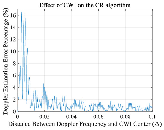
Figure 14.
Effect of CWI on the CR algorithm based on the parameter.
Figure 15 displays the deviation from the correct value as a function of the JSR. Here again, the amount of distortion depends on the distance . In both curves, stronger CWI will cause more distortion. When distance , almost for all JSR, the error is below 3%. However, in the case with distance , error dramatically increases for larger JSR.
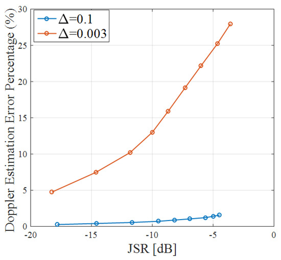
Figure 15.
Percentage of error in Doppler estimation based on JSR.
This section presented the effect of a CWI on the CFR based on the (L&R) algorithm. The closer the Doppler frequency is from the CWI’s center frequency; the more errors occur. A smart jammer can stop the receiver with low power CWI that has a center frequency close to the Doppler value.
3.4.2. Blind Carrier Recovery
The DVB-S2 transmitter has a special mode with a higher bit rate when the channel is under good communication conditions. In this mode, the pilots can be turned off and be replaced by user data for less redundancy and faster transfer speeds. In this situation, the non-data-aided algorithm or blind carrier offset recovery must be utilized for Doppler compensation to fulfill the basic operation of the digital receiver. The most used synchronizer is PLL. The symbolic structure of this synchronizer is displayed in Figure 16a.
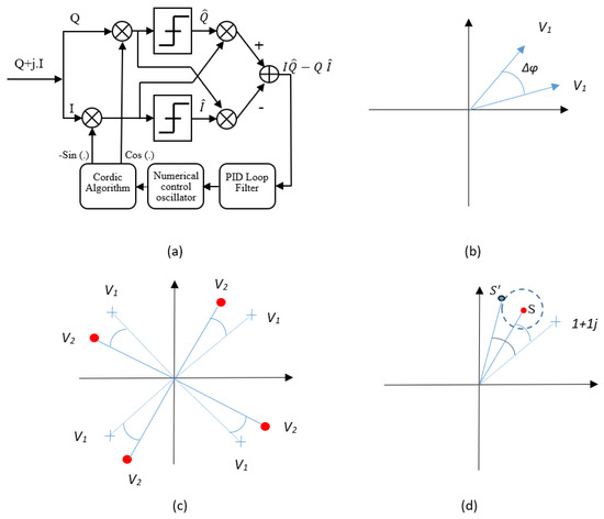
Figure 16.
Phase synchronizer based on PLL and the cross-product phase detector. (a) General block diagram (b) The phase error between two vectors (c) The phase rotation in 4QAM signal constellation (d) The deviation from original phase error in the presence of CWI.
The numerical control oscillator is the heart of almost all synchronization algorithms. It generates a frequency proper to the detected error. The phase error detector calculates the degree of rotation from the original points of the signal constellation. Considering that we have two vectors: V1 and V2, the phase between two vectors: , can be calculated with the use of the cross product (Figure 16b) [26,27]:
where , is the symbol of the cross product. It can be seen that is proportional to the imaginary part of the cross product:
The target is to calculate the phase error from the original points of the 4QAM signal constellation (Figure 16c). Thus, V2 is equal to the received symbol and V1 is equal to the nearest point from the QAM signal constellation to the symbol (in the case that the rotation is smaller than π/4). For each received symbol, V1 is equal to the summation of real sign and imaginary sign (Figure 16c):
Thus, for input symbol , the phase error is estimated based on the following cross-product phase detector [26,27]:
For simplicity, consider that the point is located in the first quarter, then:
Figure 16d represents the phase error calculation in the presence of CWI. Based on the previous discussions, the symbols start to circle around the original point by the radius of a. In this situation, deviation from the original phase error is estimated based on the following equation:
Based on the above equations and Figure 16d, it can be seen that the maximum deviation depends on the power of the interference. A similar model of the blind carrier phase detector is implemented in Matlab Simulink and the effects of CWI with different power are studied in Figure 17. In our simulations, we utilized different center frequencies that change from frequencies close to Doppler value to frequencies far from it. However, the obtained results were similar to a negligible difference. Based on the simulation performed with the phase detector, its behavior under interference is almost independent of the center frequency of the CWI and is more dependent on its power. Compared to the data-aided algorithm, blind phase detectors work independently of the center frequency and are more robust against CW interferences.
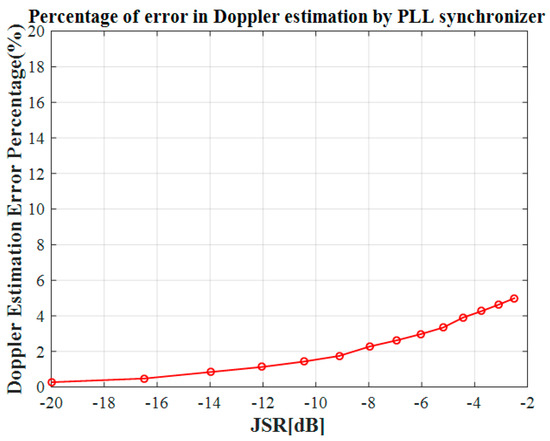
Figure 17.
Percentage of error in Doppler estimation based on JSR (PLL Synchronizer).
4. Proposed Solution and Efficiency Analysis
The adaptive notch filter is a great way to remove narrowband interference. However, before being filtered, the center frequency of the interference must be detected in order to adapt the transfer function of the filter. In Figure 18, the signal also must pass through the frequency detector (shown in the red block). Usually, a digital transmitter utilizes a pulse-shaping filter. This type of filtering compresses the signal into the narrow bandwidth. Those before the detection, downsampling can improve the system resolution. The output of the detector is the estimated center frequency () of CWI that allows the filter to adapt its frequency to the interference peak. There are different ways of center frequency detection. Two popular methods are the least mean square (LMS) [31] and the frequency domain implemented as FFT [32,33] or Welch’s method [9] followed by peak detection. This paper mainly focuses on the system performance improvement achieved by notch filtering. The main assumption here is that the center frequency of interference is precisely known by the receiver and the notch filter is adjusted to the same CWI frequency.

Figure 18.
Block diagram of the generic solution.
4.1. Notch Filter
A notch filter is a narrow band stop filter that rejects part of the signal located in a very specific frequency band. The gain drops and rises very quickly. The notch filter is utilized as a solution by filtering a single-tone CWI frequency and letting all other frequencies pass. It can also be used in multi-tone CWI mitigation by employing multi-notch filters in cascade. This greatly improves the reception performance at the cost of a slight loss of information, since a frequency band of the original signal is removed as well.
The transfer function of an IIR M-order notch filter can be expressed as following [34]:
Each represents the frequency of each gap in the notch filter and pole radius r (restricted as for stability) controls the bandwidth of each notch. By inserting M = 1, Equation (33) is simplified as the first order complex notch filter:
where is the center frequency of the adaptive notch filter. Figure 19 shows the frequency response of three notch filters with different r values and different center frequencies. For a lower value of r, the attenuation is much stronger, and the gap bandwidth is larger.
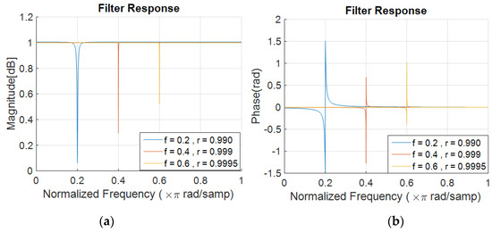
Figure 19.
Notch filters response with different r parameters. (a) Magnitude (b) Phase.
The IIR notch filter is used very often in narrowband interference mitigation, especially for GNSS receivers. It has a very simple structure that makes it suitable for practical implementation. Compared with the FIR filter with many taps and coefficients, the IIR notch filter has a simpler structure and is the heart of many narrowband interference mitigation systems because of this unique structure. The most important feature is that both center frequency and bandwidth can be adjusted adaptively by adjusting only two parameters. For the FIR filter, to adaptively remove a hopping CWI, one has to reproduce all filter taps based on the desired center and bandwidth and then change the coefficients of the filter also FIR filters have a longer convergence time. The IIR notch filter also has a linear frequency response in all of the bandwidth except in its gap bandwidth (Figure 19b). However, non-linearity in the gap is not important because this bandwidth is supposed to be removed from the signal. The general drawback of the notch filter on system performance is explained based on the SNR reduction and BER curve. The described system performance reduction is general, thus, it covers all the effects like: removed information from the original signal and effect of phase non-linearity in the frequency gap. In other words, the system performance study shows the system degradation after the notch filter puts all its effects on the desired signal that contains both amplitude and phase. Both the amplitude and phase of the signal are affected by the notch filter, then the SNR and BER after filtering are calculated. In this case, the system performance study covers both amplitude gap and phase behavior.
4.2. Effects of Notch Filtering and CWI Removal
The DVB standard is a narrow band signal, which means that a lot of information is compressed to a narrow range of frequencies [35]. A notch filter is utilized as a simple solution to attenuate the frequency that the CW interference is compromising. Frequency removal can improve the system’s performance. However, it should be considered that it also removes a part of the useful received signal. Clearly, interference cancelation for powerful interference demands a wider gap or a greater attenuation from the notch in the frequency domain, but there is a tradeoff between the amount of interference power reduction and the removed bandwidth from the signal.
To study the effect of bandwidth removal on the system’s performance, first, consider that there is no interference and a notch filter removes a part of the pure signal spectrum, in other words, the input of the notch filter is a QPSK signal with AWGN noise at variable power.
The performance degradation can be expressed based on the comparison of the SNR measurement before and after filtering. This section explains the effect of the notch filter on a QPSK signal with AWGN noise is. Figure 20 shows the block diagram of this test analysis. This test tries to clarify the negative effect of a notch filter on the system’s performance based on the SNR measurement. Only the AWGN noise is added to the signal.
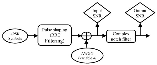
Figure 20.
Structure used to measure the effects on system performance.
The input and output SNR are measured and analyzed in Figure 21. This figure shows the variation of the output SNR for different r values. The results show that there is performance degradation related to the bandwidth of a notch filter. Clearly, a wider notch removes more information from the desired signal, therefore it will cause more SNR reduction. For a larger input SNR, the output SNR decreases much faster with the increase in the r parameter. Again here, a system with higher QoS (larger SNR) experiences more distortion. When the r increases towards a value of 1, the output SNR is approximately equal to the input SNR.
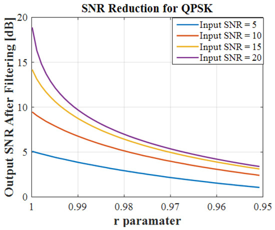
Figure 21.
Relation between output SNR and r parameter for different input SNR.
Figure 22 shows the relation between the input and output SNR for different values of r. As the notch bandwidth decreases, the output SNR increases as well for the same amount of input SNR. For a specific bandwidth, the SNR after filtering cannot exceed a certain level, even if the input SNR is increasing. These curves display the maximum available SNR at the output of the notch filters with different bandwidth. Based on this figure, it can be concluded that for a special notch bandwidth, the obtained SNR is under the threshold level, and large bandwidth will cause the residual error in the receiver.
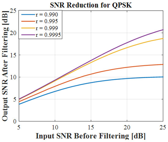
Figure 22.
Relation between output and input SNR for different r values.
The following test explains the amount of residual interference in the received signal after notch filtering. To study the performance of the notch filter in JSR reduction, the next simulation is performed under a similar situation to the block diagram in Figure 23. In this test, a CWI with variable power is added to a QPSK signal, then, the notch filter reduces the interference power. JSR measurement before and after filtering is utilized to express the filter performance with different bandwidth.
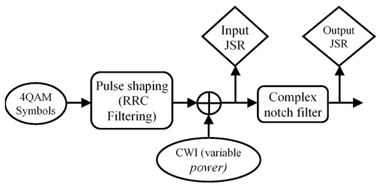
Figure 23.
Block diagram for the second test analysis.
Figure 24 shows the influence of the notch filter on the JSR reduction for the QPSK signal under the effect of a CWI. The JSR is reduced greatly after filtering (almost as much as a 10 dB improvement). The relation between the input and output of the filter is almost linear for a given r.
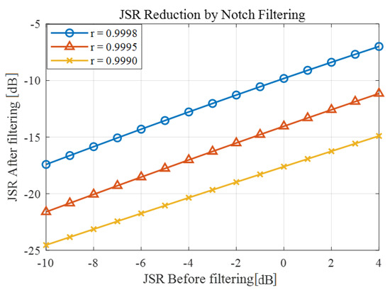
Figure 24.
Notch filter performance on JSR.
The final step combines the SNR and the JSR as shown in Figure 25. The next test and figure reveal how much the notch filter can improve the SNR in the presence of interference. Figure 25 displays the utilized situation for the next measurement. First, the White Gaussian noise with SNR = 15 dB is added to the QPSK. In the next step, a CWI is added to the noisy signal, SJNR measurement is used to express the notch filter role in system performance. Here, an AWGN noise with 15 dB SNR and a variable power CWI are added to a QPSK signal and then filtered with a proper notch filter.
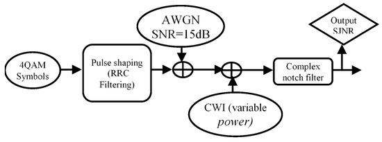
Figure 25.
Block diagram for the third test analysis.
The output SJNR is calculated and displayed in Figure 26 above. Based on this figure, specifically on the “without filtering” curve, the signal degrades dramatically as the JSR increases. Two important parameters affect the quality of the received signal, the amount of spectrum the notch filter removes from the received signal and the diffraction of samples from the original point of the signal constellation due to the CWI. For smaller JSR, when the CWI power is low, the removed bandwidth from the signal (notch filter bandwidth) is the main effect on the system performance, therefore, for low power JSR, the filter with r = 0.9999 helps to improve the SNR. In contrast, when the JSR increases, for a powerful CWI signal, the residual amount of interference after filtering starts to affect the system performance and decreases the quality of the received signal power, thus, for a larger JSR, a wider notch has the best performance. This figure could be used for adaptive adjustments of the notch filter bandwidth based on the input JSR to obtain maximum system performance.
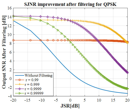
Figure 26.
Notch filter performance on SNR.
4.3. Bit Error Rate (BER)
Another important criterion for performance measurement is the bit error rate (BER). For every modulation technique, there is a different maximum BER limit before the signal can no longer be reproduced. For example, based on a simulation result, by using a QPSK modulation with a code ratio of 1/4, an image will not be received if the BER is 0.000126 and the SNR is −2.743 dB. The image will partially or completely be reproduced when the BER is 4.94 × 10⁻⁵ and the SNR is −2.713 dB.
Finally, the image will be received without any errors when the SNR is at least −2.658 dB [35]. The value of this metric is compared before and after filtering the signal in the presence of a CW interference. The bit errors are caused mostly by noise and interference which distort the original signal. Figure 27 shows a simulation of the effect of the notch filtering on the BER of the QPSK transmission under the CWI. Without any interference, the BER drops dramatically as the Energy per Bit over the Spectral Noise Density (Eb/N0) ratio increases. This is to be expected since a signal with lower AWGN noise will cause fewer errors.
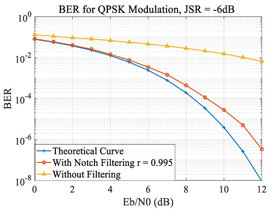
Figure 27.
BER performance of QPSK with JSR = −6 dB.
In contrast, the CWI causes a huge amount of bit errors and the received SNR cannot exceed 6 dB. When the Eb/N0 ratio is 12 dB, the BER with CWI cannot exceed the 10−2 value. After notch filtering, a significant improvement is observed, the system can continue its duty with only 1.5 dB of degradation on the SNR. The post-filtering curve is much closer to the theoretical minimum curve of the QPSK BER, especially for lower Eb/N0 ratios. At the ratio of 12 dB, the BER of filtered signal excels the curve without filtering by approximately 7 dB.
4.4. Discussion
The results show that the notch filter improves the JSR, the SNR and the BER in the presence of a CWI. Those metrics depend on the value of the r parameter and interference power. As seen in Figure 26 and Figure 27, the JSR and the BER are much improved (except for an r-value of 0.99 and JSR below −10 dB). By attenuating the interference with the notch filter, the signal keeps most of its form and can be used for successful communication at low BER.
We could argue that the notch filter and the CWI are too narrow, and if the detection of the center frequency is not good enough, not only the interference is still disturbing the signal, but some part of the signal is deleted as well. If the center frequency is moving, the algorithm must be able to follow the CWI. However, the benefits outweigh the negative since a single CW interference degrades much more the signal than the noise. Further research could focus on the precise detector itself which is as much important as the notch filter. Fast and accurate center frequency detection is necessary in order to reduce the negative impacts of the notch filter and maximize interference removal.
5. Conclusions
The CWI affects the DVB-S2 receiver in four main stages: the signal constellation, the symbol time recovery, the frame synchronization, and the carrier frequency recovery. Each stage is crucial in the functioning of the receiver and if one fails, the whole chain is broken. First, the CWI causes the signal constellations to become circles with a radius proportional to the interference power. SNR can decrease as much as 6 dB when the JSR is −15 dB. Then, interferences with high frequencies increase the timing error. The frame synchronization is also affected depending on the center frequency of the interference. A JSR of −7 dB can cause as much as 18% packet loss depending on the center frequency. Finally, CWI close to Doppler frequency greatly affects the data-aided carrier frequency recovery. When the CWI center frequency is close to the Doppler frequency, the Doppler error estimation will rise exponentially, well above 15% which is enough to cause the whole CFR to fail.
In the second part, the effect of the CWI removal with a notch filter was analyzed on a signal with and without interference as a reference. The method used here is an adaptive IIR first order notch filter preceded by a center frequency detector. Although the notch filter partially degrades the signal, it does amazing work to reduce the jamming caused by the CWI. In general, the JSR is reduced by 15 dB with only a single CWI, and, when both the AWGN and the CWI are combined, the SNR is improved by 10 dB for 0 dB JSR. An important factor that affects the improvement is the r parameter. By varying it, one can measure different improvements of the JSR and SNR.
Without filtering, the BER is 10−2 for an Eb/N0 ratio of 12 dB. However, after CWI removal by the notch filter, that value goes down to 10−6, much closer to the theoretical one which is 10−8.
On the other hand, the notch filter has a few setbacks. Since it deletes a range of frequencies, it also deletes a part of the information. This is even more noticeable when the filter’s bandwidth is larger (smaller r value). In addition, for very low JSR, the improvements are marginal and, depending on the bandwidth, the SNR could be worse.
Author Contributions
Conceptualization, M.H.S.; methodology, M.H.S.; writing—original draft preparation, M.H.S.; writing—review and editing, G.G. (Gabriel Gandubert), P.I., G.G. (Gabriel Gleeton); supervision, R.L.J. All authors have read and agreed to the published version of the manuscript.
Funding
This research is part of the project entitled AVIO-601 in LASSENA Lab (École de Technologie Supérieure) named Interference Mitigation in Satellite Communication. It is supported by the Natural Sciences and Engineering Research Council of Canada (NSERC), Thales, Telesat, VIGILANT GLOBAL, CRIAQ, and Atem Canada. Special thanks to CMC for providing the required equipment to succeed with this project.
Conflicts of Interest
The authors declare no conflict of interest.
References
- Xu, D.; Zhang, G.; Ding, X. Analysis of Co-channel Interference in Low-orbit Satellite Internet of Things. In Proceedings of the 2019 15th International Wireless Communications & Mobile Computing Conference (IWCMC), Tangier, Morocco, 24–28 June 2019; pp. 136–139. [Google Scholar]
- Wu, R.; Wang, W.; Lu, D.; Wang, L.; Jia, Q. Adaptive Interference Mitigation in GNSS; Springer Science and Business Media LLC: Berlin, Germany, 2018. [Google Scholar]
- Idris, A.N.; Suldi, A.M.; Hamid, J.R.A.; Sathyamoorthy, D. Effect of radio frequency interference (RFI) on the Global Positioning System (GPS) signals. In Proceedings of the 2013 IEEE 9th International Colloquium on Signal Processing and its Applications, Kuala Lumpur, Malaysia, 8–10 March 2013; pp. 199–204. [Google Scholar]
- Rashdan, I.; Schmidhammer, M.; Mueller, F.D.P.; Sand, S. Performance Evaluation of Vehicle-to-Vehicle Communication for Cooperative Collision Avoidance at Urban Intersections. In Proceedings of the 2017 IEEE 86th Vehicular Technology Conference (VTC-Fall), Toronto, ON, USA, 24–27 September 2017; pp. 1–5. [Google Scholar]
- Kim, J.; Iyamabo, P. Exact BER calculation of TCM-MAPSK using product trellis algorithm for DVB applications. In Proceedings of the 2017 IEEE International Symposium on Broadband Multimedia Systems and Broadcasting (BMSB), Cagliari, Italy, 7–9 June 2017; pp. 1–7. [Google Scholar]
- Andrenacci, S. Physical Layer Performance of Multi-User Detection in Broadband Multi-Beam Systems based on DVB-S2. In Proceedings of the 20th European Wireless Conference, Barcelona, Spain, 14–16 May 2014; pp. 1–5. [Google Scholar]
- Debbah, M.; Gallinaro, G.; Müller, R.; Rinaldo, R.; Vernucci, A. Interference mitigation for the reverse-link of interactive satellite networks. In Proceedings of the 9th International Workshop on Signal Processing for Space Communications (SPSC), Berlin, Germany, 10–12 September 2018. [Google Scholar]
- Ye, F.; Tian, H.; Che, F. CW interference effects on the performance of GPS receivers. In Proceedings of the 2017 Progress in Electromagnetics Research Symposium-Fall (PIERS-FALL), Singapore, 19–22 November 2017; pp. 66–72. [Google Scholar]
- Howard, R.M. The Power Spectral Density. In Principles of Random Signal Analysis and Low Noise Design; Wiley: Hoboken, NJ, USA, 2003; pp. 59–91. [Google Scholar]
- Digital Video Broadcasting (DVB). Second generation framing structure channel coding and modulation systems for broadcasting Interactive Services News Gathering and Other Broadband Satellite Applications; ETSI: Sophia Antipolis, France, 2009; pp. 12–67. [Google Scholar]
- Youssef, B.; Khalid, S.; Hajar, C.; Ahmad, B.; Abdelhamid, B.; Driss, M. Measurement and test of a DVB-S2 satellite broadcast. In Proceedings of the 2019 7th Mediterranean Congress of Telecommunications (CMT), Fes, Morocco, 24–25 October 2019; pp. 1–5. [Google Scholar]
- Chi, Y.; Chen, L.; Lv, C. A symbol timing recovery algorithm of M-PSK signals for burst modem applications with small packet size. China Commun. 2016, 13, 138–146. [Google Scholar] [CrossRef]
- Wu, H.; Sha, Z.; Huang, Z.; Zhou, Y. Frame synchronization for DVB-S2 based on scrambling sequence. In Proceedings of the 2014 International Symposium on Wireless Personal Multimedia Communications (WPMC), Sydney, Australia, 7–10 September 2014. [Google Scholar]
- Wang, H.; Yan, C.; Kuang, J.; Wu, N.; Fei, Z.; Zheng, M. Design and Analysis of Data-Aided Coarse Carrier Frequency Recovery in DVB-S2. In Proceedings of the 2010 IEEE 71st Vehicular Technology Conference, Taipei, Taiwan, 16–19 May 2010; pp. 1–2. [Google Scholar]
- Yehoshuva, C.; Veeryya, J.; Vereendra, P.; Sumit, K.; Kumar, P. Mansoor New approach of tunable notch filter for blocker suppression of multi-mode wireless devices. In Proceedings of the 2017 International Conference on Computer Communication and Informatics (ICCCI), Coimbatore, India, 5–7 January 2017; pp. 1–6. [Google Scholar]
- Wang, G.; Shu, Z.; Chen, G.; Tian, X.; Shen, D.; Pham, K.; Nguyen, T.M.; Blasch, E. Performance evaluation of SATCOM link in the presence of radio frequency interference. In Proceedings of the 2016 IEEE Aerospace Conference, Big Sky, MT, USA, 5–12 March 2016; pp. 1–10. [Google Scholar]
- Lv, Q.; Qin, H. A Novel Algorithm for Adaptive Notch Filter to Detect and Mitigate the CWI for GNSS Receivers. In Proceedings of the 2018 IEEE 3rd International Conference on Signal and Image Processing (ICSIP), Shenzhen, China, 13–15 July 2018; pp. 444–451. [Google Scholar]
- Song, N.; De Lamare, R.C.; Haardt, M.; Wolf, M. Adaptive Widely Linear Reduced-Rank Interference Suppression Based on the Multistage Wiener Filter. IEEE Trans. Signal. Process. 2012, 60, 4003–4016. [Google Scholar] [CrossRef]
- Fors, K.M.; Wiklundh, K.C.; Stenumgaard, P. On the Mismatch of Emission Requirements for CW Interference against OFDM Systems. IEEE Trans. Electromagn. Compat. 2017, 60, 1555–1561. [Google Scholar] [CrossRef]
- Raasakka, J.; Orejas, M. Analysis of notch filtering methods for narrowband interference mitigation. In Proceedings of the 2014 IEEE/ION Position, Location and Navigation Symposium-PLANS 2014, Monterey, CA, USA, 5–8 May 2014; pp. 1282–1292. [Google Scholar]
- Zou, D.; Chen, Y.; Li, Z.; Li, F.; Ding, L.; Sun, Y.; Li, J.; Sui, Q.; Yi, X.; Li, Z. Comparison of null-subcarriers reservation and adaptive notch filter for narrowband interference cancellation in intra-data center interconnect with DMT signal transmission. Opt. Express 2019, 27, 5696–5702. [Google Scholar] [CrossRef] [PubMed]
- Li, F.; Zou, D.; Ding, L.; Sun, Y.; Li, J.; Sui, Q.; Li, L.; Yi, X.; Li, Z. 100 Gbit/s PAM4 signal transmission and reception for 2-km interconnect with adaptive notch filter for narrowband interference. Opt. Express 2018, 26, 24066–24074. [Google Scholar] [CrossRef] [PubMed]
- Kang, H.; No, J.-S. Narrow-Band Interference Removing Filter for Mobile Communication Systems. In Proceedings of the 2018 Tenth International Conference on Ubiquitous and Future Networks (ICUFN), Prague, Czech Republic, 3–6 July 2018; pp. 603–606. [Google Scholar]
- Gardner, F. A BPSK/QPSK Timing-Error Detector for Sampled Receivers. IEEE Trans. Commun. 1986, 34, 423–429. [Google Scholar] [CrossRef]
- Zhang, Y.; Chen, X.; Fan, W.; Han, J.; Zeng, X. Robust and reliable frame synchronization method for DVB-S2 system. In Proceedings of the 2010 Wireless Telecommunications Symposium (WTS), Tampa, FL, USA, 21–23 April 2010; pp. 1–5. [Google Scholar] [CrossRef]
- Luise, M.; Reggiannini, R. Carrier frequency recovery in all-digital modems for burst-mode transmissions. IEEE Trans. Commun. 1995, 43, 1169–1178. [Google Scholar] [CrossRef]
- Rice, M.; Dick, C.; Harris, F. Maximum likelihood carrier phase synchronization in FPGA-based software defined radios. Inst. Electr. Electron. Eng. 2002, 2, 889–892. [Google Scholar]
- De Lima, E.R.; Queiroz, A.F.R.; Alves, D.C.; Da Silva, G.S.; Chaves, C.G.; Mertes, J.G.; Marson, T.M. A detailed DVB-S2 receiver implementation: FPGA prototyping and preliminary ASIC resource estimation. In Proceedings of the 2014 IEEE Latin-America Conference on Communications (LATINCOM), Cartagena de Indias, Colombia, 5–7 November 2014. [Google Scholar]
- Deng, X.; Tian, M.; Luo, Y.; Li, J. Optimization and Implementation of Programmable Demodulator for MPSK MPSK MPSK/16 QAM Signals. Int. J. Digit. Content Technol. Its Appl. (JDCTA) 2012, 6, 91–98. [Google Scholar] [CrossRef]
- Hou, Y.; Xiong, H.; Xiang, H.; Ma, B.; Xiong, J. Simulation Analysis of Multipath Fading Channel Characteristics in Satellite Communication System. In Proceedings of the 2019 IEEE 3rd Advanced Information Management, Communicates, Electronic and Automation Control Conference (IMCEC), Chongqing, China, 11–13 October 2019; pp. 1367–1370. [Google Scholar]
- Varshney, N.; Jain, R.C. An adaptive notch filter for narrow band interference removal. In Proceedings of the 2013 National Conference on Communications (NCC), New Delhi, India, 15–17 February 2013; pp. 1–5. [Google Scholar]
- DiPietro, R. An FFT based technique for suppressing narrow-band interference in PN spread spectrum communications systems. In Proceedings of the International Conference on Acoustics, Speech, and Signal Processing, Orlando, FL, USA, 13–17 May 2002. [Google Scholar]
- Zhang, J.; Lohan, E. Effect and mitigation of narrowband interference on Galileo E1 signal acquisition and tracking accuracy. In Proceedings of the 2011 International Conference on Localization and GNSS (ICL-GNSS), Tampere, Finland, 29–30 June 2011; pp. 36–41. [Google Scholar]
- Borio, D.; Camoriano, L.; Presti, L.L. Two-Pole and Multi-Pole Notch Filters: A Computationally Effective Solution for GNSS Interference Detection and Mitigation. IEEE Syst. J. 2008, 2, 38–47. [Google Scholar] [CrossRef]
- Baotic, P.; Draganic, M.; Bundalo, D.; Kesegic, I.; Tralic, D.; Grgic, S. Simulation model of DVB-S2 system. In Proceedings of the ELMAR-2013, Zadar, Croatia, 25–27 September 2013; pp. 227–231. [Google Scholar]
Publisher’s Note: MDPI stays neutral with regard to jurisdictional claims in published maps and institutional affiliations. |
© 2020 by the authors. Licensee MDPI, Basel, Switzerland. This article is an open access article distributed under the terms and conditions of the Creative Commons Attribution (CC BY) license (http://creativecommons.org/licenses/by/4.0/).