Advanced Noncoherent Detection in Massive MIMO Systems via Digital Beamspace Preprocessing


Abstract
1. Introduction
2. System Model
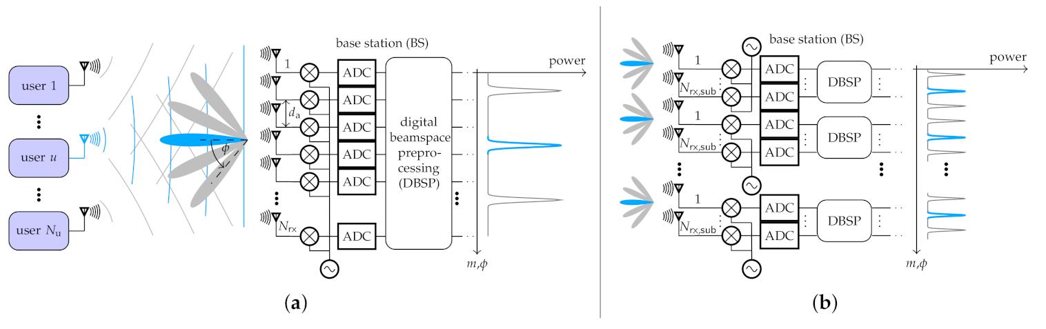
2.1. System Overview
2.2. Channel Model
2.3. Noncoherent Detection
2.4. Digital Beamspace Preprocessing
2.4.1. Full-Array
2.4.2. Sub-Array
3. Numerical Results
3.1. Full-Array vs. Sub-Array Architecture
3.2. Influence of Propagation Channel
4. Conclusions
Author Contributions
Funding
Conflicts of Interest
References
- Gupta, A.; Jha, R.K. A Survey of 5G Network: Architecture and Emerging Technologies. IEEE Access 2015, 3, 1206–1232. [Google Scholar] [CrossRef]
- Marzetta, T.L. Noncooperative Cellular Wireless with Unlimited Numbers of Base Station Antennas. IEEE Trans. Wirel. Commun. 2010, 9, 3590–3600. [Google Scholar] [CrossRef]
- Larsson, E.G.; Edfors, O.; Tufvesson, F.; Marzetta, T.L. Massive MIMO for Next Generation Wireless Systems. IEEE Commun. Mag. 2014, 52, 186–195. [Google Scholar] [CrossRef]
- Rusek, F.; Persson, D.; Lau, B.K.; Larsson, E.G.; Marzetta, T.L.; Edfors, O.; Tufvesson, F. Scaling Up MIMO: Opportunities and Challenges with Very Large Arrays. IEEE Signal Process. Mag. 2013, 30, 40–60. [Google Scholar] [CrossRef]
- Andrews, J.G.; Buzzi, S.; Choi, W.; Hanly, S.V.; Lozano, A.; Soong, A.C.K.; Zhang, J.C. What Will 5G Be? IEEE J. Sel. Areas Commun. 2014, 32, 1065–1082. [Google Scholar] [CrossRef]
- Lu, L.; Li, G.Y.; Swindlehurst, A.L.; Ashikhmin, A.; Zhang, R. An Overview of Massive MIMO: Benefits and Challenges. IEEE J. Sel. Top. Signal Process. 2014, 8, 742–758. [Google Scholar] [CrossRef]
- Elijah, O.; Leow, C.Y.; Rahman, T.A.; Nunoo, S.; Iliya, S.Z. A Comprehensive Survey of Pilot Contamination in Massive MIMO—5G System. IEEE Commun. Surv. Tutor. 2016, 18, 905–923. [Google Scholar] [CrossRef]
- Stojanovic, M.; Proakis, J.; Catipovic, J. Analysis of the Impact of Channel Estimation Errors on the Performance of a Decision-Feedback Equalizer in Fading Multipath Channels. IEEE Trans. Commun. 1995, 43, 877–886. [Google Scholar] [CrossRef]
- Peng, W.; Adachi, F.; Ma, S.; Wang, J.; Ng, T.S. Effects of Channel Estimation Errors on V-BLAST Detection. In Proceedings of the IEEE Global Telecommunications Conference (GLOBECOM), New Orleans, LA, USA, 30 November–4 December 2008. [Google Scholar] [CrossRef]
- Marzetta, T.L.; Larsson, E.G.; Yang, H. Fundamentals of Massive MIMO; Cambridge University Press: Cambridge, UK, 2016. [Google Scholar]
- Schenk, A.; Fischer, R.F.H. Noncoherent Detection in Massive MIMO Systems. In Proceedings of the 17th International ITG Workshop on Smart Antennas (WSA), Stuttgart, Germany, 13–14 March 2013; pp. 1–8. [Google Scholar]
- Fischer, R.F.H.; Bense, M. Noncoherent Decision-Feedback Equalization in Massive MIMO Systems. In Proceedings of the International Zurich Seminar on Communications (IZS), Zurich, Switzerland, 26–28 February 2014; pp. 112–115. [Google Scholar] [CrossRef]
- Fischer, R.F.H.; Bense, M.; Stierstorfer, C. Noncoherent Joint Decision-Feedback Detection in Multi-User Massive MIMO Systems. In Proceedings of the 18th International ITG Workshop on Smart Antennas (WSA), Erlangen, Germany, 12–13 March 2014; pp. 1–8. [Google Scholar]
- Yammine, G.; Fischer, R.F.H. Feedback-Aware Noncoherent Receivers for Massive MIMO Systems. In Proceedings of the 24th International ITG Workshop on Smart Antennas (WSA), Hamburg, Germany, 18–20 February 2020; pp. 1–6. [Google Scholar]
- Bucher, S.; Yammine, G.; Fischer, R.F.H.; Waldschmidt, C. Influence of Channel Parameters on Noncoherent Massive MIMO Systems. In Proceedings of the 22nd International ITG Workshop on Smart Antennas (WSA), Bochum, Germany, 14–16 March 2018. [Google Scholar]
- Bucher, S.; Ragab, A.N.; Yammine, G.; Fischer, R.F.H.; Waldschmidt, C. Antenna Design for Noncoherent Massive MIMO Systems. In Proceedings of the 15th International Symposium on Wireless Communication Systems (ISWCS), Lisbon, Portugal, 28–31 August 2018. [Google Scholar] [CrossRef]
- Bucher, S.; Yammine, G.; Fischer, R.F.H.; Waldschmidt, C. On the Impact of Hardware Impairments in Noncoherent Massive MIMO Systems. In Proceedings of the 24th International ITG Workshop on Smart Antennas (WSA), Hamburg, Germany, 18–20 February 2020. [Google Scholar]
- Bense, M.; Weigel, R. Channel Measurements for the Evaluation of Noncoherent Massive MIMO Systems. In Proceedings of the 47th European Microwave Conference (EuMC), Nuremberg, Germany, 10–12 October 2017. [Google Scholar] [CrossRef]
- Yammine, G.; Bucher, S.; Fischer, R.F.H. Noncoherent Detection for an EM-Lens-Enabled Massive MIMO System. In Proceedings of the International ITG Conference on Systems, Communication and Coding (SCC), Rostock, Germany, 11–14 February 2019. [Google Scholar]
- Bucher, S.; Yammine, G.; Fischer, R.F.H.; Waldschmidt, C. A Noncoherent Massive MIMO System Employing Beamspace Techniques. IEEE Trans. Veh. Technol. 2019, 68, 11052–11063. [Google Scholar] [CrossRef]
- Zeng, Y.; Zhang, R.; Chen, Z.N. Electromagnetic Lens-Focusing Antenna Enabled Massive MIMO: Performance Improvement and Cost Reduction. IEEE J. Sel. Areas Commun. 2014, 32, 1194–1206. [Google Scholar] [CrossRef]
- Zeng, Y.; Zhang, R. Millimeter Wave MIMO With Lens Antenna Array: A New Path Division Multiplexing Paradigm. IEEE Trans. Commun. 2016, 64, 1557–1571. [Google Scholar] [CrossRef]
- Zeng, Y.; Yang, L.; Zhang, R. Multi-User Millimeter Wave MIMO With Full-Dimensional Lens Antenna Array. IEEE Trans. Wirel. Commun. 2018, 17, 2800–2814. [Google Scholar] [CrossRef]
- Zeng, Y.; Zhang, R. Cost-Effective Millimeter-Wave Communications with Lens Antenna Array. IEEE Wirel. Commun. 2017, 24, 81–87. [Google Scholar] [CrossRef]
- Kwon, T.; Lim, Y.; Chae, C. Limited Channel Feedback for RF Lens Antenna Based Massive MIMO Systems. In Proceedings of the International Conference on Computing, Networking and Communications (ICNC), Kauai, HI, USA, 15–18 February 2015; pp. 6–10. [Google Scholar] [CrossRef]
- Kwon, T.; Lim, Y.G.; Min, B.W.; Chae, C.B. RF Lens-Embedded Massive MIMO Systems: Fabrication Issues and Codebook Design. IEEE Trans. Microw. Theory Tech. 2016, 64, 2256–2271. [Google Scholar] [CrossRef]
- Sayeed, A.; Behdad, N. Continuous Aperture Phased MIMO: Basic Theory and Applications. In Proceedings of the 48th Annual Allerton Conference on Communication, Control, and Computing (Allerton), Monticello, IL, USA, 29 Septembet–1 October 2010; pp. 1196–1203. [Google Scholar] [CrossRef]
- Brady, J.; Behdad, N.; Sayeed, A.M. Beamspace MIMO for Millimeter-Wave Communications: System Architecture, Modeling, Analysis, and Measurements. IEEE Trans. Antennas Propag. 2013, 61, 3814–3827. [Google Scholar] [CrossRef]
- Amadori, P.V.; Masouros, C. Low RF-Complexity Millimeter-Wave Beamspace-MIMO Systems by Beam Selection. IEEE Trans. Commun. 2015, 63, 2212–2223. [Google Scholar] [CrossRef]
- Huang, W.; Huang, Y.; Zeng, Y.; Yang, L. Wideband Millimeter Wave Communication With Lens Antenna Array: Joint Beamforming and Antenna Selection With Group Sparse Optimization. IEEE Trans. Wirel. Commun. 2018, 17, 6575–6589. [Google Scholar] [CrossRef]
- Shen, W.; Bu, X.; Gao, X.; Xing, C.; Hanzo, L. Beamspace Precoding and Beam Selection for Wideband Millimeter-Wave MIMO Relying on Lens Antenna Arrays. IEEE Trans. Signal Process. 2019, 67, 6301–6313. [Google Scholar] [CrossRef]
- Balanis, C.A. Antenna Theory: Analysis and Design, 3rd ed.; John Wiley & Sons: Hoboken, NJ, USA, 2005. [Google Scholar]
- Liu, L.; Oestges, C.; Poutanen, J.; Haneda, K.; Vainikainen, P.; Quitin, F.; Tufvesson, F.; Doncker, P.D. The COST 2100 MIMO Channel Model. IEEE Wirel. Commun. 2012, 19, 92–99. [Google Scholar] [CrossRef]
- Verdone, R.; Zanella, A. Pervasive Mobile and Ambient Wireless Communications; Springer: London, UK, 2012. [Google Scholar] [CrossRef]
- Yammine, G.; Fischer, R.F.H.; Waldschmidt, C. On the Influence of the Antenna Pattern in Noncoherent Massive MIMO Systems. In Proceedings of the International Symposium on Wireless Communication Systems (ISWCS), Brussels, Belgium, 25–28 August 2015; pp. 391–395. [Google Scholar] [CrossRef]
- Krim, H.; Viberg, M. Two Decades of Array Signal Processing Research: The Parametric Approach. IEEE Signal Process. Mag. 1996, 13, 67–94. [Google Scholar] [CrossRef]
- Veen, B.V.; Buckley, K. Beamforming: A Versatile Approach to Spatial Filtering. IEEE ASSP Mag. 1988, 5, 4–24. [Google Scholar] [CrossRef]
- Manolakis, D.G.; Ingle, V.K.; Kogon, S.M. Statistical and Adaptive Signal Processing: Spectral Estimation, Signal Modeling, Adaptive Filtering and Array Processing; Artech House: Norwood, MA, USA, 2005. [Google Scholar]
- Van Trees, H.L. Optimum Array Processing; Wiley-Blackwell: Hoboken, NJ, USA, 2002. [Google Scholar]
- Li, J.; Stoica, P. Robust Adaptive Beamforming; John Wiley & Sons, Inc.: Hoboken, NJ, USA, 2005. [Google Scholar] [CrossRef]
- Capon, J. High-Resolution Frequency-Wavenumber Spectrum Analysis. Proc. IEEE 1969, 57, 1408–1418. [Google Scholar] [CrossRef]
- Schmidt, R. Multiple Emitter Location and Signal Parameter Estimation. IEEE Trans. Antennas Propag. 1986, 34, 276–280. [Google Scholar] [CrossRef]
- Roy, R.; Kailath, T. ESPRIT-Estimation of Signal Parameters via Rotational Invariance Techniques. IEEE Trans. Acoust. Speech Signal Process. 1989, 37, 984–995. [Google Scholar] [CrossRef]
- Yu, J.L.; Yeh, C.C. Generalized Eigenspace-Based Beamformers. IEEE Trans. Signal Process. 1995, 43, 2453–2461. [Google Scholar] [CrossRef]
- Foschini, G.J.; Chizhik, D.; Gans, M.J.; Papadias, C.; Valenzuela, R.A. Analysis and Performance of Some Basic Space-Time Architectures. IEEE J. Sel. Areas Commun. 2003, 21, 303–320. [Google Scholar] [CrossRef]
- Del Re, E.; Morosi, S.; Marabissi, D.; Mucchi, L.; Pierucci, L.; Ronga, L.S. Reconfigurable Antenna for Future Wireless Communication Systems. Wirel. Pers. Commun. 2007, 42, 405–430. [Google Scholar] [CrossRef]

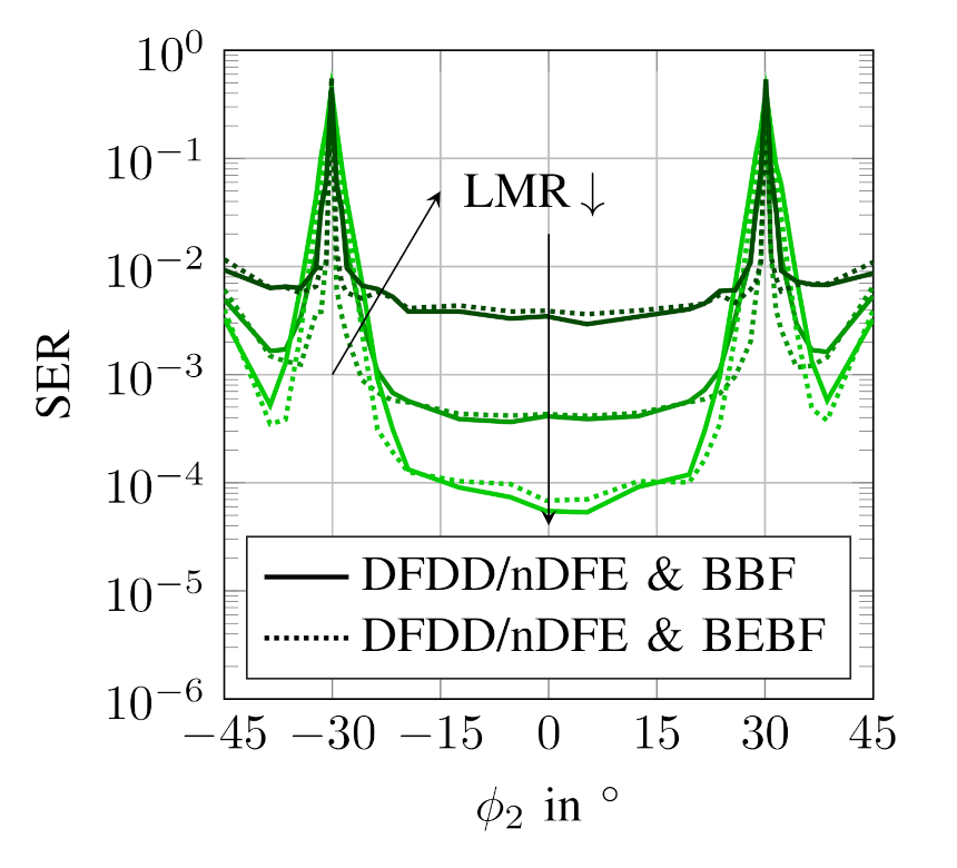
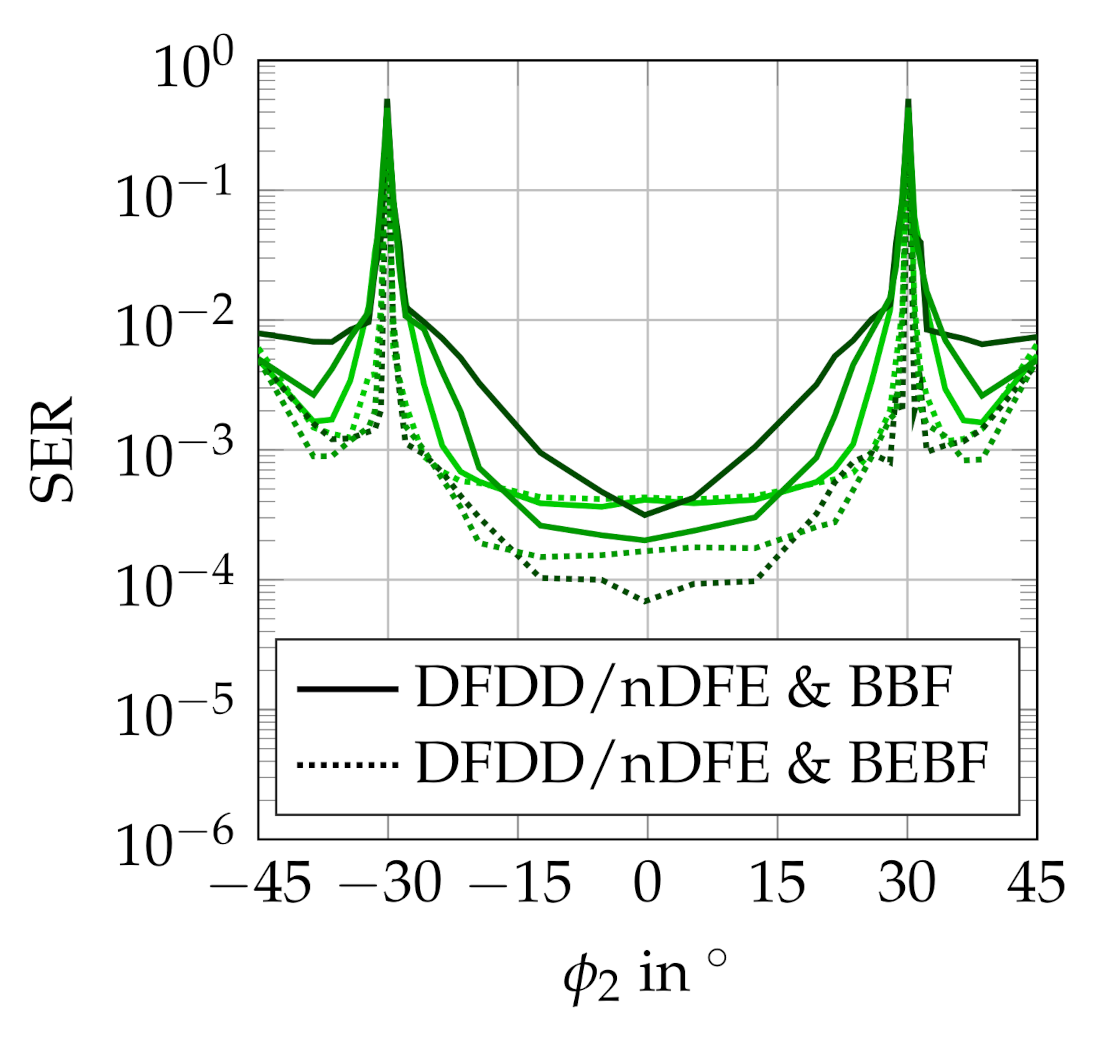
 ) and in case of a combination with eigenspace-based post-processing (
 ) considering two incident waves (
 /
/ ) and a field of view (FoV) of = .
) and in case of a combination with eigenspace-based post-processing () considering two incident waves (/) and a field of view (FoV) of = .
) and a field of view (FoV) of = .
) and in case of a combination with eigenspace-based post-processing () considering two incident waves (/) and a field of view (FoV) of = .

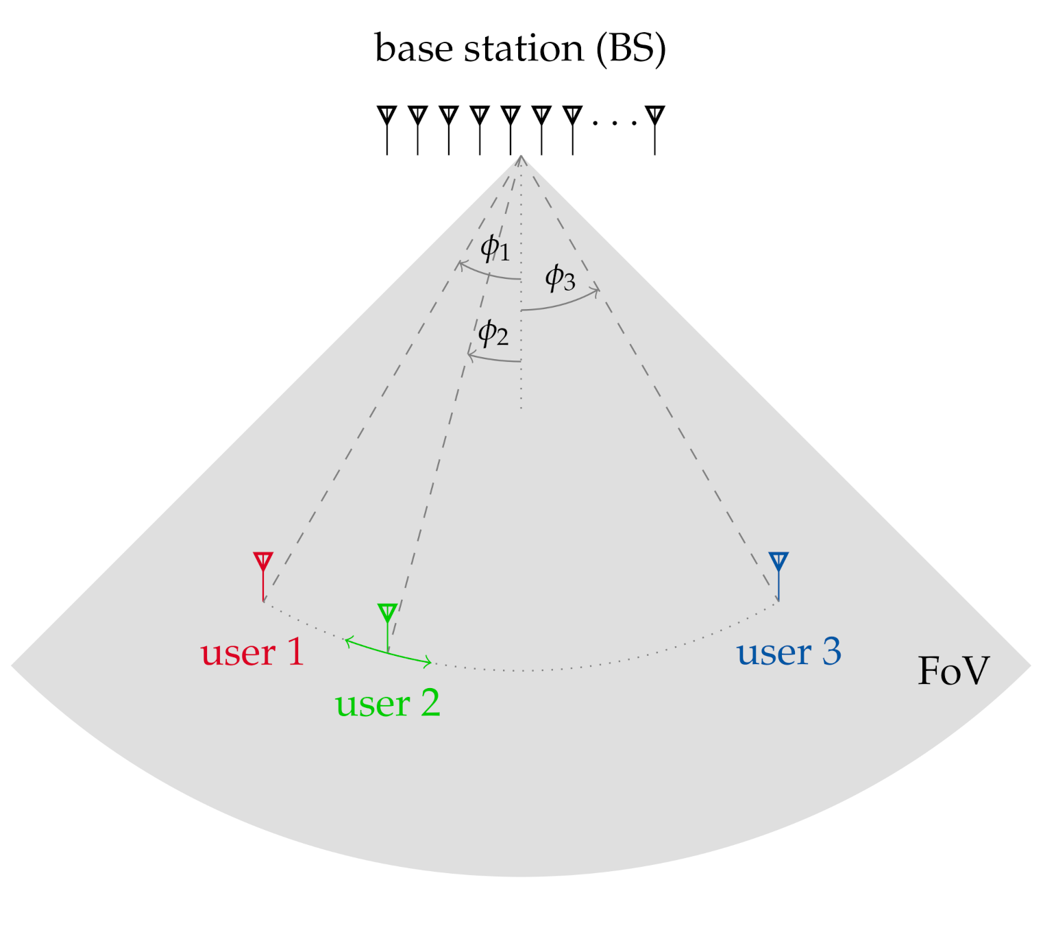
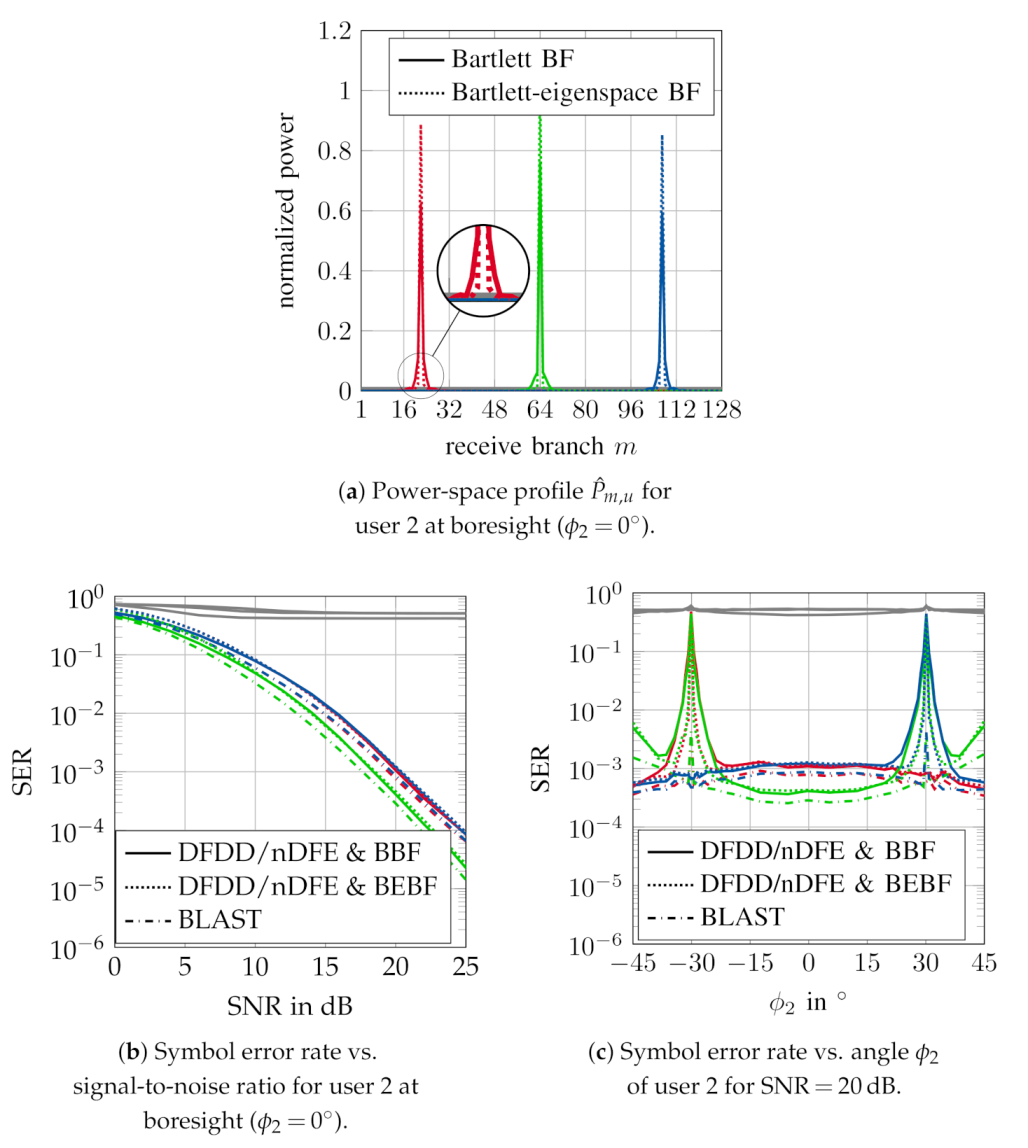
 ), user 2 (
 ), user 3 (
 ). Gray plots (
 ) represent results without digital beamspace preprocessing for each user.
), user 2 (), user 3 (). Gray plots () represent results without digital beamspace preprocessing for each user.
) represent results without digital beamspace preprocessing for each user.
), user 2 (), user 3 (). Gray plots () represent results without digital beamspace preprocessing for each user. ), user 2 (), user 3 (). Gray plots () represent results without digital beamspace preprocessing for each user.
), user 2 (), user 3 (). Gray plots () represent results without digital beamspace preprocessing for each user.
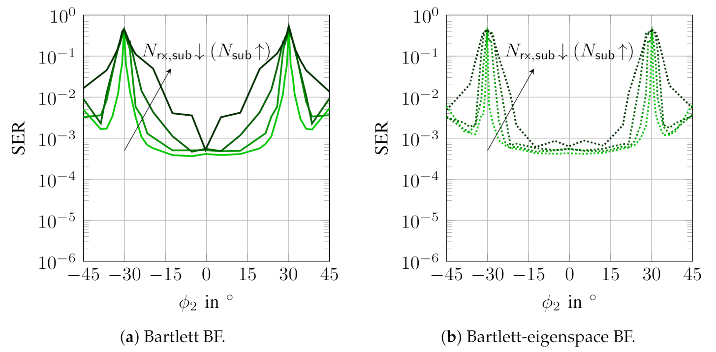
), user 2 (), user 3 (). Gray plots () represent results without digital beamspace preprocessing for each user. ) and for different sub-array configurations ( = 4 and = 32 (
 ), = 8 and = 16 (
 ), = 16 and = 8 (
 )).
) and for different sub-array configurations ( = 4 and = 32 (), = 8 and = 16 (), = 16 and = 8 ()).
)).
) and for different sub-array configurations ( = 4 and = 32 (), = 8 and = 16 (), = 16 and = 8 ()). ), = (), = ().
), = (), = ().
), = (), = (). ), = (), = ().
), = (), = ().
), = (), = ().

| System Configuration | |
| number of users | 3 |
| number of BS antennas | 128 |
| BS antenna spacing | |
| FoV | |
| user antenna type | omni-directional |
| BS antenna type | patch [15] |
| angle of user | = , , = |
| Noncoherent Detection | |
| modulation alphabet | 4-ary DPSK |
| block length | 201 |
| Propagation Channel | |
| cluster types | local |
| number of multi-path components | 3 |
| angular spread at BS | variable |
| LOS-to-MPC ratio (LMR) | variable |
| number of different channel realizations | |
| channel normalization (power control) | = |
Publisher’s Note: MDPI stays neutral with regard to jurisdictional claims in published maps and institutional affiliations. |
© 2020 by the authors. Licensee MDPI, Basel, Switzerland. This article is an open access article distributed under the terms and conditions of the Creative Commons Attribution (CC BY) license (http://creativecommons.org/licenses/by/4.0/).
Share and Cite
Bucher, S.; Waldschmidt, C. Advanced Noncoherent Detection in Massive MIMO Systems via Digital Beamspace Preprocessing. Telecom 2020, 1, 211-227. https://doi.org/10.3390/telecom1030015
Bucher S, Waldschmidt C. Advanced Noncoherent Detection in Massive MIMO Systems via Digital Beamspace Preprocessing. Telecom. 2020; 1(3):211-227. https://doi.org/10.3390/telecom1030015
Chicago/Turabian StyleBucher, Stephan, and Christian Waldschmidt. 2020. "Advanced Noncoherent Detection in Massive MIMO Systems via Digital Beamspace Preprocessing" Telecom 1, no. 3: 211-227. https://doi.org/10.3390/telecom1030015
APA StyleBucher, S., & Waldschmidt, C. (2020). Advanced Noncoherent Detection in Massive MIMO Systems via Digital Beamspace Preprocessing. Telecom, 1(3), 211-227. https://doi.org/10.3390/telecom1030015