Article

Experimental Investigation on the Effect of Heating Oil and Tyre Pyrolysis Oil Combustion in an Evaporative Combustion Chamber

by
István Péter Kondor
Department of Innovative Vehicles and Materials, University of John von Neumann, Izsáki Str. 10, H-6000 Kecskemét, Hungary
Fuels 2024, 5(2), 210-221; https://doi.org/10.3390/fuels5020012
Submission received: 21 November 2023 / Revised: 4 February 2024 / Accepted: 14 March 2024 / Published: 28 May 2024

Abstract

:
This research aims to delve into the intricacies of combustion processes, specifically focusing on heating oil and a blend of heating oil with Tire Pyrolysis Oil (TPO) in a self-developed evaporative combustion chamber featuring steam injection. The primary objective is to scrutinize the impact of steam injection on the combustion dynamics. Conducting a series of tests, the investigation involved the meticulous manipulation of stoichiometric ratios while introducing ambient air through gravity fuel flow. Subsequent iterations of these tests incorporated the introduction of steam into the ambient air stream. The examination encompassed the combustion of both heating oil and the TPO blend within the combustion chamber. The evaluation criteria comprised an in-depth analysis of flame characteristics, temperature distribution within the combustion chamber, and the quantification of emissions such as particulate matter (PM), nitrogen oxides (NOx), carbon dioxide (CO2), carbon monoxide (CO), and water vapor (H2O). Throughout the experimentation phase, commercially available diesel fuel served as the primary fuel source. To facilitate the tests, the combustion chamber under scrutiny was seamlessly integrated into an AVL engine test bench system. Essential parameters, including fuel consumption, were meticulously gauged using an AVL 735 fuel flow meter, while fuel temperature was monitored using the AVL 745 fuel temperature conditioning system. The intake air, a crucial element in the combustion process, was quantified with precision using an AVL Flowsonix sensor. Emission measurements were conducted meticulously using state-of-the-art equipment, with gaseous emissions analyzed using an AVL FTIR AMA i60 exhaust gas analyzer. Simultaneously, soot emissions were quantified through employment of an AVL Micro Soot sensor. This comprehensive approach not only delves into the fundamental aspects of combustion but also extends its reach to the exploration of innovative techniques, such as steam injection, to enhance combustion efficiency and reduce emissions. The integration of advanced measurement tools ensures a robust and thorough analysis of the combustion process and its environmental implications.

1. Introduction

In the contemporary context, the European Union finds itself grappling with the repercussions of the energy crisis and the geopolitical tensions arising from the war in Ukraine, both of which have synergistically propelled the cost of natural gas to unprecedented heights within its borders. The focus has shifted from mere economic considerations of gas prices to a critical concern about the very availability of this vital energy resource in the near future. In response to this looming crisis, the EU has implemented legislation mandating a substantial reduction in gas consumption, compelling a shift toward alternative energy sources to meet heating demands, particularly in the realm of residential and industrial applications [1,2,3]. As a viable substitute for natural gas, various forms of oil—whether fossil, bio, or synthetic—have emerged as focal points in the quest for energy diversification. Fossil oils, exemplified by readily available heating oil with properties akin to diesel fuel, have historically played a role in industrial and power plant settings, and until recently, were commonly used for household heating. However, the ascendancy of natural gas, owing to its cost-effectiveness and convenience, has relegated heating oil to a secondary position [4]. In the pursuit of mitigating emissions and enhancing the efficiency of oil-based energy systems, steam injection has emerged as a noteworthy technique. Extensive literature research has revealed its application, primarily in internal combustion diesel engines, as a means to alter the dynamics of the combustion process. Armas et al. observed a faster combustion process, decreased combustion temperature, and reduced concentrations of NOx, HC, and particulate matter (PM) through steam injection [5]. Further studies by Kökkülünk et al. demonstrated that simulation results aligned closely with experimental data, showcasing an increase in engine torque and effective power by up to 2.5%, along with significant reductions in NOx and CO2 emissions [6]. Additional insights from Lin and Wang highlighted the multifaceted impacts of steam injection, including decreased exhaust temperature, lowered levels of O2, NOx, and smoke, alongside increased CO2 and CO emissions [7]. It is noteworthy that much of the existing research primarily delves into the intricacies of processes occurring within internal combustion engines. This collective body of knowledge underscores the urgency and complexity of the current energy landscape, necessitating innovative solutions and alternative technologies to navigate the challenges posed by the escalating costs and diminishing availability of natural gas in the European Union.
During the measurements, standard commercial heating oil and TPO fuel were tested. Since TPO fuel is not commercially available, it had to be tested in an accredited testing laboratory, where its physical and chemical parameters were determined. This test was carried out in the Eurofins laboratory. The heating oil is commercially available, so separate laboratory tests were not necessary during the measurement, they are provided by MOL. The difference between heating oil and diesel oil is in the color and excise tax classification.
The physical and chemical properties of the two fuels are summarized in Table 1.

1.1. Technical Parameters of the Combustion Chamber

This research delves into the examination of a uniquely designed evaporative combustion chamber tailored for the combustion of liquid fuels. Within evaporative combustion chambers, the interplay between gravity and ambient pressure air significantly influences the behavior of the liquid fuel during the combustion process. The cylindrical configuration of the combustion chamber incorporates circular vertical pipes strategically designed to enhance heat release. To optimize the combustion efficiency, a thoughtful air supply mechanism has been implemented. Ambient air is introduced into the lower part of the combustion chamber through meticulously drilled circular holes, ensuring a thorough and efficient mixing of air with the liquid fuel. The air control was done by a throttle valve built into the intake manifold. Gravity facilitates the downward flow of the liquid fuel from the fuel tank, filling the bottom of the combustion chamber. Notably, the bottom of the combustion chamber exhibits a dual-layered structure. On the outer part, ambient air is directed into the chamber, complementing the combustion process. Simultaneously, the inner tray at the bottom facilitates the controlled intake of liquid fuel. The inner tray is designed with small circular holes on the side, allowing air to ingress into the combustion zone, further optimizing the combustion reaction. Figure 1 illustrates a detailed 3D model of the combustion chamber, showcasing its cylindrical form with integrated circular vertical pipes and the intricate arrangement of components. The construction material chosen for the combustion chamber is a hot-rolled alloy steel plate, specifically A572GR.50, interconnected through a welding process. This choice of material ensures robustness and durability, crucial for withstanding the harsh conditions associated with combustion processes. In summary, this study not only investigates the functionality of the evaporative combustion chamber but also emphasizes the importance of design elements such as the cylindrical structure, circular pipes, and dual-layered bottom for effective heat release and combustion efficiency. The use of A572GR.50 alloy steel as the construction material further underscores the commitment to durability and reliability in the performance of the combustion chamber.
The dimensions of the combustion chamber are illustrated in Figure 2.

1.2. Experimental Setup

The measurement system employed in this study is seamlessly integrated with a standard AVL engine brake system. The entire process involves the precise control and monitoring of fuel flow, with fuel originating from the fuel tank and passing through a series of components, including a flow meter, conditioner, and pressure regulator, before entering the combustion chamber. The regulator allows for meticulous adjustment of the fuel flow, ensuring optimal conditions for combustion. Simultaneously, the combustion chamber draws in the necessary air from the surrounding environment. Dilution of the flue gas is performed automatically by the measuring equipment. This incoming air is directed through a flow meter, and its volume can be finely tuned using a dedicated valve. This dual-control mechanism—fuel flow and air intake—facilitates a comprehensive exploration of combustion dynamics. To assess the environmental impact of the combustion process, the concentration of harmful substances is meticulously analyzed. Exhaust gases emanating from the combustion chamber are sampled for this purpose. The Micro Soot Sensor (MSS) system is employed to measure the amount of soot content, providing insights into particulate matter. Additionally, the gas concentrations are determined using Fourier-Transform Infrared Spectroscopy (FTIR) equipment, allowing for a detailed analysis of various gas components. For a visual representation of the experimental setup, refer to Figure 3, which depicts the schematic diagram of the entire system. This comprehensive setup ensures accurate and controlled measurements, laying the foundation for a thorough investigation into combustion characteristics and emissions in the context of the AVL engine brake system.
In order to comprehensively analyze the combustion process, a meticulous examination of both the heat distribution within the combustion and the temperature conditions of the combustion chamber was conducted. This investigation was facilitated through the utilization of a FLIR thermal camera, which enabled precise measurements at various points throughout the combustion chamber. The introduction of steam into the combustion chamber was orchestrated by an industrial steam generator, the detailed specifications of which can be found in Table 2. This steam injection process was strategically implemented directly in front of the air inlets, a crucial placement that played a pivotal role in influencing the combustion dynamics. The FLIR thermal camera served as an invaluable tool in capturing real-time data, allowing for an in-depth analysis of the heat distribution patterns during the combustion process. This comprehensive approach not only shed light on the overall efficiency of the combustion, but also provided crucial insights into the interplay between steam injection and combustion dynamics within the chamber. The industrial steam generator, as outlined in Table 2, played a central role in regulating the steam injection parameters, ensuring a controlled and precisely managed introduction of steam into the combustion chamber. The synchronized interaction of these components created an environment conducive to a thorough understanding of the combustion behavior and its implications for temperature distribution within the system.

2. Exhaust Gas and Particulate Matter Measurement Method

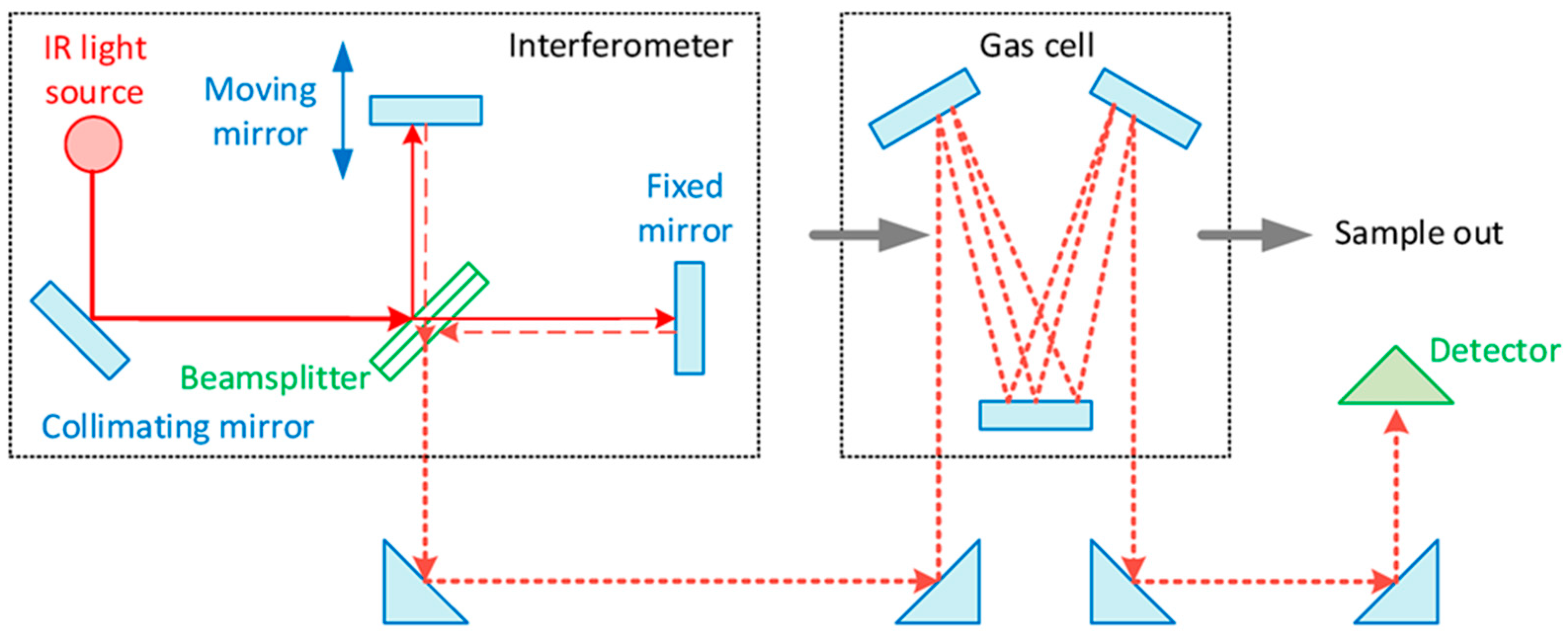
The type of equipment used during the measurements is an AVL SESAM i60 FT SII (AVL List GmbH, Graz, Austria), a Fourier transform infrared (FTIR) spectrometer. Its measurement principle is based on absorption and reflection. A gas scanned with broad-spectrum infrared light absorbs light rays of certain frequencies and transmits others. The frequency of the absorbed light is the same as the natural frequency of the vibrational modes of the gas molecules, or the harmonics of these frequencies. The ratio of the absorbed light is the same as the concentration ratio of the gas being tested. So, the spectrum of the passing absorbed frequency gives the type of gas, and the amount of absorbed light gives the concentration of the gas being tested [8]. Figure 4 schematically illustrates how the infrared light is introduced through a modulator into a cuvette in which the gas to be analyzed is flowed. The modulator modulates the light, so it splits it into different wavelengths, and when the light passes through the cuvette, the detector detects the amount of light passing through. From the sensed signal, the electronics infers the degree of absorption, which it converts into the concentration of the analyzed gases using Fourier transformation.
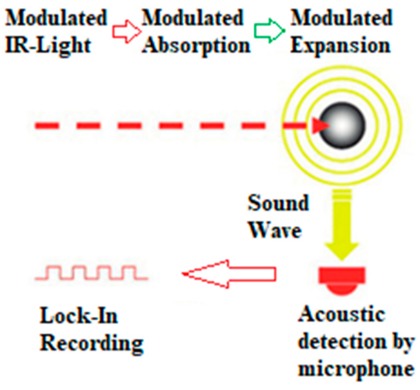
The AVL Micro Soot Sensor (AVL483) is a sophisticated measuring device employed for the quantification of soot concentration. Operating on the photoacoustic principle, this device utilizes a unique method to assess the concentration of emitted soot. The underlying measurement principle hinges on the distinctive optical properties of soot particles; being black and inherently dark in color, they exhibit a high absorption capacity for light. This absorption phenomenon is vividly depicted in Figure 4. In practical terms, the measuring process involves modulating the measuring light, which is then directed towards the soot particles within the exhaust gas to be analyzed. Due to their dark nature, the soot particles readily absorb the modulated measuring light. This absorption results in the heating of the sample gas, a crucial step in the measurement process [10]. To carry out the measurement, the AVL Micro Soot Sensor extracts a sample from the exhaust gas under examination. This sample is then subjected to illumination, and the ensuing absorption of measuring light facilitates the heating of the sample gas. The device’s capacity to effectively capture and analyze the soot concentration in this manner underscores its precision and reliability in environmental and combustion studies.
The process of measuring soot concentration involves the dynamic response of the sample gas in the measuring chamber to changes in temperature and soot particle concentration. Upon heating, the sample gas undergoes expansion, while a reduction in soot particles leads to contraction. This contraction is a consequence of reduced light absorption by fewer soot particles, causing a sudden cooling of the sample gas within the resonant cell, as depicted in Figure 5. The expansion and contraction events generate a discernible sound wave, akin to an acoustic signal, which can be easily captured by a microphone and subsequently transmitted to the control unit for analysis. One notable advantage of this instrument is its ability to directly measure soot concentration without succumbing to cross-sensitivity issues with other components present in the exhaust gas. This specificity is crucial for accurate assessments of soot levels. Additionally, the instrument is proficient in conducting raw exhaust gas measurements, a capability achieved through the ingenious application of thermophoretic loss compensation (TLC). The engineers ingeniously implemented TLC to address challenges arising from thermophoretic deposits at the exhaust gas sampling location. These deposits could lead to a shortage of soot particles in the measured sample. By compensating for this deficiency, TLC ensures that the measured quantity of soot particles is appropriately adjusted to account for any discrepancies introduced by thermophoretic deposits [11]. This feature enhances the instrument’s precision and reliability, making it a valuable tool for exhaust gas analysis in various applications.
The accuracy of the measuring instruments is summarized in Table 3.

3. Measurement Points

The measurements were made at twelve points, so that for three types of fuel flow values (0.3; 0.6; 1 kg/h), four types of air flow values (10; 40; 70; 100%) were set. The measurement results are presented for a fuel consumption value of 1 kg/h. The measurement protocol was compiled based on the experience of a previous measurement, in which the TPO was tested in a diesel engine [9]. Most of the measurement errors are normally distributed. The normal distribution has the advantage of being mathematically tractable. The statistical estimations and tests are based on this are based on this distribution. The probability of a normal distribution is the density function of the variable:
f x = 1 σ 2 π e x µ 2 2 σ 2
A probability variable with a normal distribution is just as likely to be values greater than μ and less than μ, and values significantly different from μ, with much lower probability than the μ close to μ. μ and σ are arbitrary numbers (σ > 0), and the distribution is given by two parameters. μ is the expected value of the probability variable, and σ is the standard deviation. These two parameters completely define the normal distribution. For the expected value of a random variable with a normal distribution, the best estimate is the arithmetic mean:
x ¯ = i = 1 n x i n
There is a significant measurable difference in the gas emission at the selected test points. Each measurement point was measured three times. The duration time of the measurements was one minute. The values obtained during sampling are automatically averaged by the measuring instrument, and the plotted point is displayed as the average of the three measurements.

3.1. Soot Emission

Furthermore, the impact of water vapor on NOx concentration was also investigated, as highlighted in previous studies [12]. The findings revealed a positive influence on both soot and NOx levels. The initial analysis focused on the evolution of soot emissions, with results presented in the first table. Notably, the measurements proceeded from right to left in the diagram, representing a transition from higher to lower throttle positions. The variations in stoichiometry across different working points contributed to distinct values in soot emissions. In the case of diesel fuel, a noteworthy reduction of approximately half in soot emissions was observed at the measured points, underscoring the effectiveness of water vapor. Interestingly, when considering the TPO + Heating oil mixture, a particularly favorable outcome emerged, showcasing a drastic reduction in soot emissions across all measured points. Figure 6 supplements these findings by illustrating the soot concentration for each fuel mixture at various stoichiometric ratios. This visual representation offers a comprehensive view of how different fuel mixtures, in conjunction with varying stoichiometric conditions, influence soot emissions. The observed trends further emphasize the potential of water vapor in mitigating soot concentrations, especially when combined with specific fuel blends.

3.2. NOx Emission

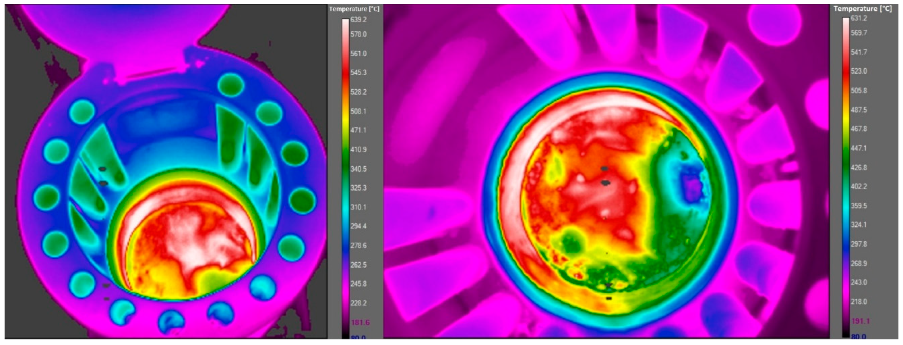
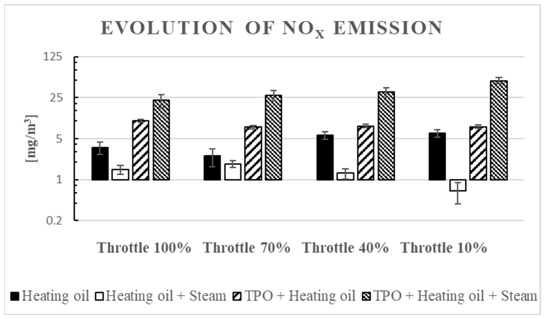
In the realm of NOx emissions, a parallel pattern emerged akin to the observed trend with carbon black. The introduction of water vapor exhibited a noteworthy reduction in NOx levels for both diesel and diesel TPO blends. These findings align with the outcomes documented in studies focusing on water vapor injections within internal combustion engines [5], thereby substantiating the empirical evidence garnered during our measurements. The mechanism behind the reduction in NOx emissions lies predominantly in the heat-absorbing attributes of water vapor. Upon injection, water vapor plays a pivotal role in extracting heat from the combustion process, consequently mitigating the flame temperature. This pivotal factor is underscored by the temperature distribution profiles depicted in Figure 6. A visual examination of the combustion chamber reveals a distinct disparity between configurations without water vapor injection (left) and those with water vapor injection (right) in Figure 7. The non-uniform heat distribution in the combustion chamber without water vapor injection underscores the intricacies of combustion by evaporation. This process, while essential for energy release, introduces challenges from an emissions standpoint. The uneven distribution of heat can contribute to suboptimal combustion conditions, leading to heightened emissions, particularly NOx. Consequently, the incorporation of water vapor emerges not only as a strategy for temperature moderation, but also as a means to foster a more uniform and controlled combustion environment, thereby contributing to the overall reduction of harmful emissions.
The evolution of the NOx concentration at the measurement points is shown in Figure 8.

3.3. CO2 Emission

Furthermore, the elevated concentration of carbon dioxide in the TPO + Heating oil mixture with water vapor can be attributed to the heightened temperature during combustion. The combustion process of the TPO and Heating oil blend generates increased heat, leading to more significant production of carbon dioxide. Additionally, the uneven distribution of the mixture further contributes to this phenomenon. The inhomogeneous mixture distribution results in varying combustion rates across different regions, influencing the overall carbon dioxide output. In Figure 9, the representation of CO2 concentrations for each fuel mixture at different stoichiometric ratios provides a visual depiction of the observed trends. The varying stoichiometric ratios highlight the impact of the air-to-fuel ratio on carbon dioxide emissions, emphasizing the importance of understanding and optimizing combustion conditions for environmental considerations [13].

3.4. CO Emission

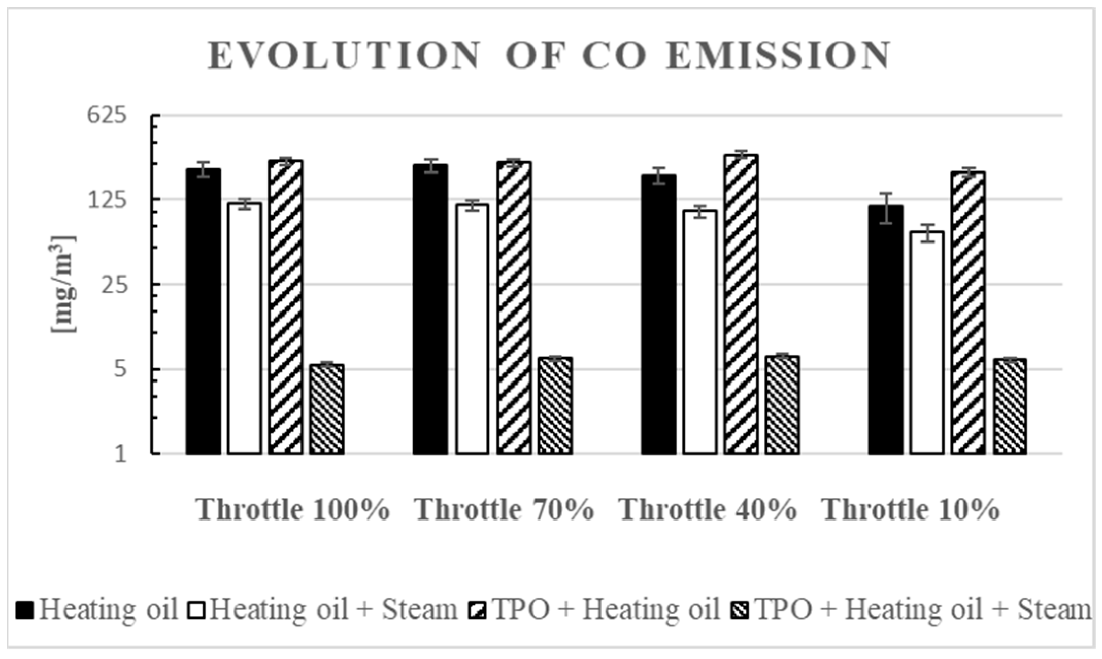
The addition of water vapor resulted in a significant reduction in carbon monoxide (CO) concentration across all measured operating points. Notably, the extent of this decrease was found to be closely tied to the stoichiometric ratio. The stoichiometric ratio plays a pivotal role in determining the magnitude of carbon monoxide concentration in the observed scenarios. In instances where there is an excess of air, the CO concentration in the flue gas is influenced by both the inhomogeneous mixture distribution and the composition of the mixture [14]. This implies that variations in the distribution of the mixture and its overall composition significantly impact the levels of carbon monoxide present in the flue gas. For a more comprehensive understanding, Figure 10 illustrates the carbon monoxide concentration for each fuel mixture across different stoichiometric ratios. This graphical representation provides a visual insight into how changes in the stoichiometric ratio affect the concentration of carbon monoxide, highlighting the dynamic nature of this relationship in the presence of water vapor. These findings underscore the importance of considering both the stoichiometric ratio and mixture characteristics when analyzing and optimizing combustion processes to minimize carbon monoxide emissions.

3.5. Water Concentration

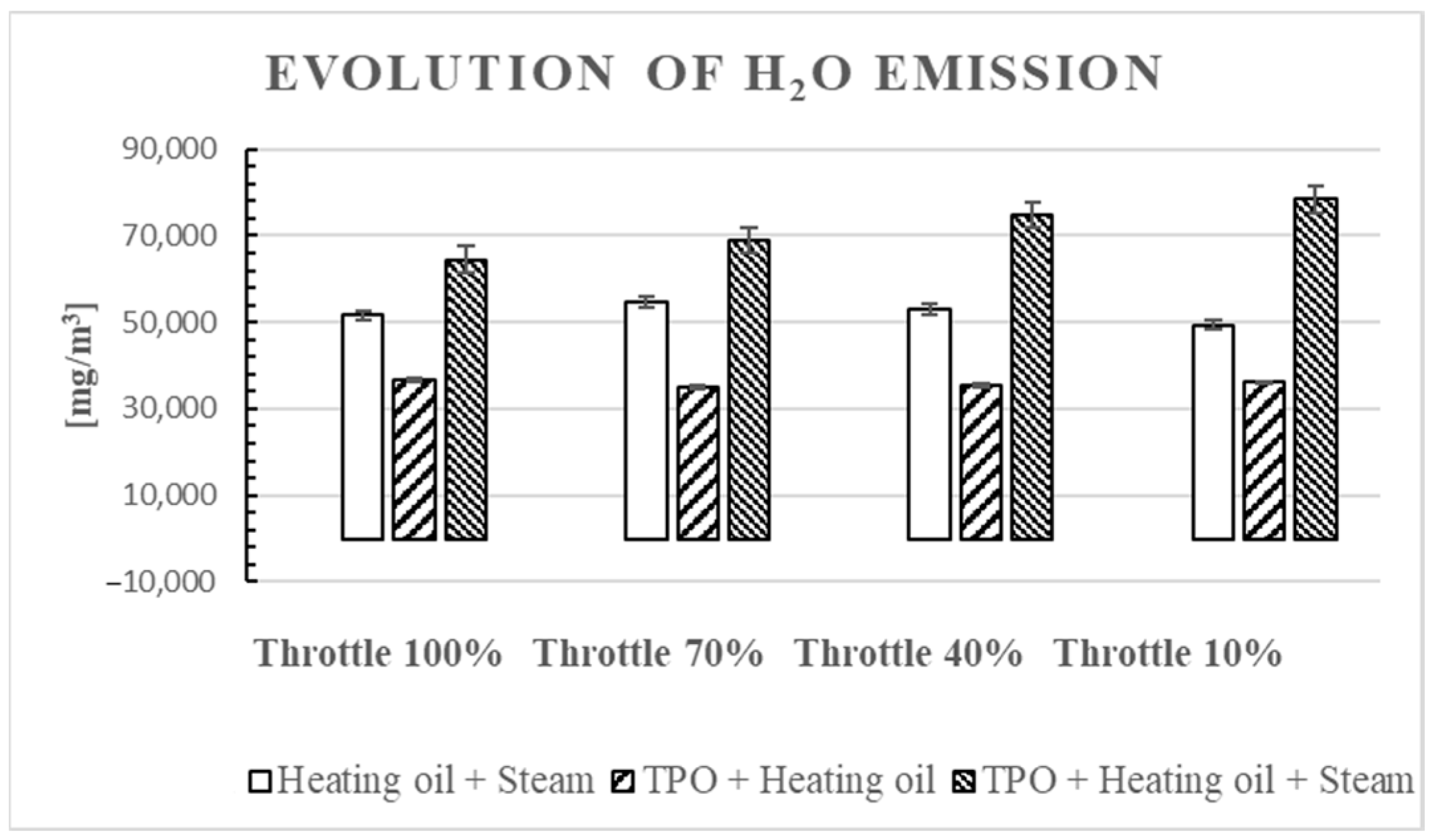
At the measurement point where diesel was assessed, the concentration of water was negligible and could not be quantified. Conversely, when examining the TPO combined with Heating oil, the presence of water became evident. This is attributed to the inherently higher water content in TPO compared to heating oil. The discernible water content in the TPO + Heating oil mixture is graphically represented in Figure 11, highlighting the contrast in water concentrations between the two fuel compositions at the respective measurement points.
The water content of the heating oil is below 200 mg/kg, which is contained in the report issued during the laboratory tests of the fuel. During combustion, the water content was not measured in the case of Heating oil due to the very low value.

4. Conclusions

In this research, the profound impact of water vapor on combustion processes has come to light. Scientific understanding has established that water molecules can undergo separation at elevated temperatures, specifically within the range of 1000–1650 °C [15]. This thermal process results in the generation of hydrogen and hydroxyl, which subsequently transform into water vapor through thermal decomposition. This decomposition can be orchestrated within a combustion device, effectively occurring in the combustion chamber. The high-temperature environment of the combustion chamber triggers the decomposition of water vapor, giving rise to active hydroxyl and hydrogen, acting as focal points that expedite the breakdown of hydrocarbons. This acceleration, in turn, enhances the combustion rate within the chamber. The catalytic influence of water vapor on combustion becomes evident as hydroxyl and formed hydrogen molecules undergo oxidation, producing water and hydrogen atoms. Notably, atomic-level hydrogen further amplifies the generation of hydroxyl, perpetuating the cycle until equilibrium is reached concerning temperature, fuel quantity, and water vapor concentration [16].
Remarkably, water vapor exhibits a catalytic role that practically eliminates gas-phase soot formation. However, caution is warranted, as an excessive concentration of water vapor in the combustion chamber can prove detrimental. The substantial volume of water vapor serves to excessively cool the combustion chamber and the fuel–air mixture, leading to delayed ignition and a protracted combustion process. Additionally, an overabundance of introduced steam may significantly elevate the production of carbon monoxide (CO) during combustion, owing to supercooling effects [17,18].
Furthermore, water vapor exerts a nuanced influence on combustion emissions by marginally lowering the flame combustion temperature. This reduction, while beneficial for mitigating thermal nitrogen oxides (NOx) production, underscores the delicate balance required in managing water vapor concentrations to optimize combustion efficiency and minimize undesirable side effects [19]. Consequently, understanding and controlling the presence of water vapor within the combustion process emerge as critical considerations for achieving optimal performance and emission profiles.

Funding

This research received no external funding.

Data Availability Statement

The data are the product of individual intellectual work, but I will make this material available to interested researchers on request.

Conflicts of Interest

The author declares no conflict of interest.

Nomenclature

AVLAnstalt für Verbrennungskraftmaschinen List
EUEuropean Union
TPOTire Pyrolysis Oil
H2OJust Add Water
PMParticulate Matter
NONitrogen Oxides
COCarbone Monoxide
CO2Carbon Dioxide
HCHydrogen Carbon
FTIRFourier Transform Infrared Spectroscopy
TLCThermophoretic loss compensation
MSZHungarian Standard
MOLHungarian Oil and Gas Company
NOxNitrous oxide

References

  1. Rodríguez-Fernández, L.; Fernández Carvajal, A.B.; Ruiz-Gómez, L.M. Evolution of European Union’s energy security in gas supply during Russia–Ukraine gas crises (2006–2009). Energy Strategy Rev. 2020, 30, 100518. [Google Scholar] [CrossRef]
  2. Von Homeyer, I.; Oberthür, S.; Jordan, A.J. EU climate and energy governance in times of crisis: Towards a new agenda. J. Eur. Public Policy 2021, 28, 959–979. [Google Scholar] [CrossRef]
  3. Jirušek, M. The attitude of the Visegrad Group Countries towards Russian Infrastructural Projects in the gas sector. Energy Policy 2020, 139, 111340. [Google Scholar] [CrossRef]
  4. Ederington, L.H.; Fernando, C.S.; Hoelscher, S.; Lee, T.K.; Linn, S.C. A Review of the Evidence on the Relation Between Crude Oil Prices and Petroleum Product Prices. SSRN Electron. J. 2018, 1–47. [Google Scholar] [CrossRef]
  5. Armas, O.; Ballesteros, R.; Martos, F.; Agudelo, J. Characterization of light duty Diesel engine pollutant emissions using water-emulsified fuel. Fuel 2005, 84, 1011–1018. [Google Scholar] [CrossRef]
  6. Kökkülünk, G.; Gonca, G.; Ayhan, V.; Cesur, İ.; Parlak, A. Theoretical and experimental investigation of diesel engine with steam injection system on performance and emission parameters. Appl. Therm. Eng. 2013, 54, 161–170. [Google Scholar] [CrossRef]
  7. Lin, C.Y.; Wang, K.H. Diesel engine performance and emission characteristics using the three-phase emulsions as fuel. Fuel 2004, 83, 537–545. [Google Scholar] [CrossRef]
  8. Bak, J.; Clausen, S. FTIR emission spectroscopy methods and procedures for real time quantitative gas analysis in industrial environments. Meas. Sci. Technol. 2001, 13, 150–156. [Google Scholar] [CrossRef]
  9. Kondor, I.P.; Zöldy, M.; Mihály, D. Experimental Investigation on the Performance and Emission Characteristic of Cmpression Ignition Engine Using Waste Based Tire Pyrolysis Fuel and Diesel Fuel Blends. Energies 2021, 14, 7903. [Google Scholar] [CrossRef]
  10. Gonca, G.; Sahin, B.; Parlak, A.; Ust, Y.; Ayhan, V.; Cesur, İ.; Boru, B. The effects of steam injection on the performance and emission parameters of a Miller cycle diesel engine. Energy 2014, 78, 266–275. [Google Scholar] [CrossRef]
  11. Grob, B.; Schmid, J.; Ivleva, N.P.; Niessner, R. Conductivity for Soot Sensing: Possibilities and Limitations. Anal. Chem. 2012, 84, 3586–3592. [Google Scholar] [CrossRef] [PubMed]
  12. Zhang, Z.; Fuehrhapter, R.; Waschl, H.; Del Re, L. Calibration and Performance of a Novel In-situ Soot Sensor for Production Engines. Procedia Eng. 2016, 168, 43–46. [Google Scholar] [CrossRef]
  13. Pyshyev, S.; Lypko, Y.; Chervinskyy, T.; Fedevych, O.; Kuatzynski, M.; Pstrowska, K. Application of tyre derived pyrolysis oil as a fuel component. South Afr. J. Chem. Eng. 2023, 43, 342–347. [Google Scholar] [CrossRef]
  14. Hadia, F.; Wadhah, S.; Ammar, H.; Ahmed, O. Investigation of combined effects of compression ratio and steam injection on performance, combustion and emissions characteristics of HCCI engine. Case Stud. Therm. Eng. 2017, 10, 262–271. [Google Scholar] [CrossRef]
  15. Xue, J.; Grift, T.E.; Hansen, A.C. Effect of biodiesel on engine performances and emissions. Renew. Sustain. Energy Rev. 2011, 15, 1098–1116. [Google Scholar] [CrossRef]
  16. Bayramoglu, K.; Nuran, M. Energy, exergy, sustainability evaluation of the usage of pyrolytic oil and conventional fuels in diesel engines. Process Saf. Environ. Prot. 2024, 181, 324–333. [Google Scholar] [CrossRef]
  17. Froissart, M.; Ochrymiuk, T. Novel wet combustion chamber concept CFD studies with triple water inlet. Energy 2023, 278 Pt A, 127854. [Google Scholar] [CrossRef]
  18. Zembi, J.; Battistani, M.; Mariani, F.; Irimescu, A.; Vaglieco, B.M.; Merola, S.S. Investigations on the impact of port water injection on soot formation in a DISI engine through CFD simulations and optical methods. Fuel 2023, 337, 127170. [Google Scholar] [CrossRef]
  19. Wu, J.; Lv, Y.; Kang, Z.; Lv, Y.; Deng, J.; Li, L.; Wu, Z. A novel approach of water injection optimization applied in gasoline engines: An investigation on heated water injection. Fuel 2023, 340, 127607. [Google Scholar] [CrossRef]
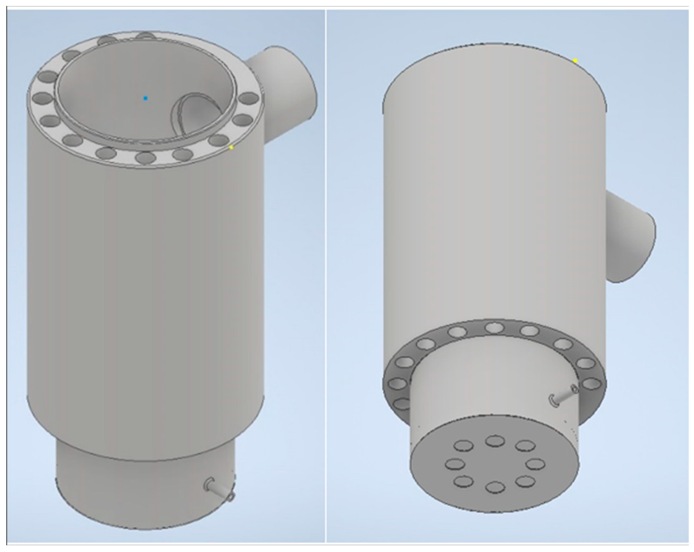
Figure 1. Combustion chamber 3D model.
Fuels 05 00012 g001
Figure 2. Dimensions of combustion chamber.
Fuels 05 00012 g002
Figure 3. Schematic diagram of the experimental setup.
Fuels 05 00012 g003
Figure 4. AVL FTIR schematic diagram [9].
Fuels 05 00012 g004
Figure 5. Schematic diagram of photoacoustic principle [9].
Fuels 05 00012 g005
Figure 6. Evolution of soot emission in the examined measurement point.
Fuels 05 00012 g006
Figure 7. Temperature distribution in the combustion chamber for a TPO + Heating oil blend at 100% throttle position with a fuel consumption of 1 kg/h.
Fuels 05 00012 g007
Figure 8. Evolution of NOx in the examined measurement point.
Fuels 05 00012 g008
Figure 9. CO2 evolution in the examined measurement point.
Fuels 05 00012 g009
Figure 10. Evolution of CO emission in the examined measurement point.
Fuels 05 00012 g010
Figure 11. Water concentration in the examined measurement point.
Fuels 05 00012 g011
Table 1. Physical and chemical properties of the fuel.
ParameterTPOHeating OilDieselStandard
ColorBlackRedYellow
Cetane<30≥51.0≥51.0MSZ EN ISO 5165
Sulfur [mg/kg]8348≤10≤10MSZ EN ISO 20846
Water [mg/kg]1804≤200≤200MSZ EN ISO 12937
Pensky-Martens Flashpoint<24>55>55MSZ EN 2719
Caloric Value [Mj/kg]40.842.742.7
Ash [%/m/m]0.005≤0.01≤0.01MSZ EN ISO 6245
Viscosity [mm2/s]4.4432.00–4.502.00–4.50MSZ EN ISO 2104
Mechanical impurities [mg/kg]0.027–0.16≤24≤24MSZ EN 12662
Density [kg/m3]926830830
Coke residue [%/m/m]0.6≤0.30≤0.30EN ISO 10370
Cold Filter Point (CFPP) ≤5≤5MSZ EN 116
Polycycle carbohydrates22–35<8.0<8.0MSZ EN 12916
Table 2. Technical specification of the Humapress HV6 steam generator.
Maximum steam capacity6 kg/h
Working pressure3 bar
Water inlet pressure4 bar
Boiler capacity15 L
Maximum steam pressure6 bar
Steam temperature354 °C
Feed water temperature20 °C
Warm-up time15 min
Heating power5 kW
Supply voltage380 V
Table 3. The accuracy of the measuring instruments.
Measured ComponentsNO and NOxTHC and CH4CO2CO
Reproducibility≤0.5% of range full scale≤0.5% of range full scale≤0.5% of range full scale≤0.5% of range full scale
Linearity≤2% of measured value (10–100% of range full scale)
≤1% of range full scale whichever is smaller
≤2% of measured value (10–100% of range full scale)
≤1% of range full scale whichever is smaller
≤2% of measured value (10–100% of range full scale)
≤1% of range full scale whichever is smaller
≤2% of measured value (10–100% of range full scale)
≤1% of range full scale whichever is smaller
Disclaimer/Publisher’s Note: The statements, opinions and data contained in all publications are solely those of the individual author(s) and contributor(s) and not of MDPI and/or the editor(s). MDPI and/or the editor(s) disclaim responsibility for any injury to people or property resulting from any ideas, methods, instructions or products referred to in the content.