Article

Functionalized Thermoplastic Polyurethane Nanofibers: An Innovative Triboelectric Energy Generator

by
Julia Isidora Salas
1,2,
Diego de Leon
1,3,
Sk Shamim Hasan Abir
1,2,
M. Jasim Uddin
1,3,* and
Karen Lozano
2,4,*
1
Photonics and Energy Research Laboratory, University of Texas Rio Grande Valley, Edinburg, TX 78539, USA
2
Department of Mechanical Engineering, University of Texas Rio Grande Valley, Edinburg, TX 78539, USA
3
Department of Chemistry, University of Texas Rio Grande Valley, Edinburg, TX 78539, USA
4
Center for Nanotechnology, University of Texas Rio Grande Valley, Edinburg, TX 78539, USA
*
Authors to whom correspondence should be addressed.
Electron. Mater. 2023, 4(4), 158-167; https://doi.org/10.3390/electronicmat4040014
Submission received: 29 August 2023 / Revised: 11 October 2023 / Accepted: 12 December 2023 / Published: 18 December 2023

Abstract

:
A triboelectric nanogenerator (TENG) is one of the most significantly innovative microdevices for built-in energy harvesting with wearable and portable electronics. In this study, the forcespinning technology was used to synthesize a nanofiber (NF) mat-based TENG. Polyvinylidene fluoride (PVDF) membrane was used as the negative triboelectric electrode/pole, and chemically designed and functionalized thermoplastic polyurethane (TPU) was used as the positive electrode/pole for the TENG. The electronic interference, sensitivity, and gate voltage of the synthesized microdevices were investigated using chemically modified bridging of multi-walled carbon nanotubes (MWCNT) with a TPU polymer repeating unit and bare TPU-based positive electrodes. The chemical functionality of TPU NF was integrated during the NF preparation step. The morphological features and the chemical structure of the nanofibers were characterized using a field emission scanning electron microscope and Fourier-transform infrared spectroscopy. The electrical output of the fabricated MWCNT-TPU/PVDF TENG yielded a maximum of 212 V in open circuit and 70 µA in short circuit at 240 beats per minute, which proved to be 79% and 15% higher than the TPU/PDVF triboelectric nanogenerator with an electronic contact area of 3.8 × 3.8 cm2, which indicates that MWCNT enhanced the electron transportation facility, which results in significantly enhanced performance of the TENG. This device was further tested for its charging capacity and sensory performance by taking data from different body parts, e.g., the chest, arms, feet, hands, etc. These results show an impending prospect and versatility of the chemically functionalized materials for next-generation applications in sensing and everyday energy harvesting technology.

1. Introduction

Each year, the number of portable devices used for essential energy harvesting, communication, patient monitoring, biosensors, etc. increases. Hence, powering, maintaining, and properly disposing of each one of these devices seems to be an almost impossible task [1]. Therefore, energy harvesting from the environment offers a possible solution due to the abundant energy resources available, such as solar, thermal, mechanical, etc. [2,3,4,5]. Based on the principle of transforming mechanical energy into electrical energy reported by Wang et al. [6], the triboelectric nanogenerator (TENG) was made [7,8]. TENGs contain two layers of materials with dissimilar electronic molecular polarity; when these two are in contact, an opposite electronic (static) pole appears on the surfaces due to contact electrification [9,10]. An electrode is attached to each triboelectric layer, through which charges can flow through it to an external circuit [11]. A potential difference is created when the materials are separated due to the charge density (polarization) difference [12].
Even though the mechanism of charge generation between two polymers remains ambiguous, further tests should be carried out to measure the charge density of polymer-polymer, so as to not dismiss the rest of the sources of charge [13,14,15]. We also know that the strength of the charge depends on the types of materials used and on their tendency to gain or lose electrons [16]. So, the selection of materials with good charge generation is the principal consideration in fabricating a TENG [12]. Numerous materials have been tested for energy harvesting with TENGs, and different polymeric materials have been used due to the flexibility, breathability, and ease of giving different shapes to the TENG device with good charge transfer capability [17,18,19,20,21]. PDVF [22] is broadly studied for piezoelectric nanogenerators due to its β-phase, piezoelectric coefficient, good stability, and flexibility [23,24,25,26], but its high electron affinity, spontaneous, and stable polarization makes it a promising material to be used in TENGs [27,28]. As for the positive layer, TPU nanofibers (NFs) have not been studied widely, but these nanofibers have good stretchability and a better electron ejection capacity [11,21]. To boost the performance of triboelectric nanogenerators, surface modifications have been made by incorporating various functional groups with different materials [9,22,25,26]. Recently, MWCNT has been added to one of the triboelectric layers to improve the energy conversion efficiency owing to improved surface charge density of TPU [29,30,31,32]. MWCNT have a high aspect ratio and high conductivity and have been widely used in polymeric matrices to improve the electrical and mechanical properties [33]. Furthermore, polymer-based nanofibers offer better stretchability and effective contact surface area compared to polymer films. These characteristics have favored the study of NF-based TENG as a motion sensor, specifically to detect the mechanical response of human motion [11,34,35,36]. Scheme 1 shows a schematic structure of the TENG that was used for this project; in Scheme 1a, it can be observed that the different layers that the structure has and the functionality of each were previously described; in Scheme 1b, a representation of the nanofibers that are the structure of the PVDF and TPU layer can be observed.
In this study, PVDF nanofiber was synthesized by the Forcespinning® technique (McAllen, Texas, USA), which was used as a negative layer (electronic pole) in the triboelectric nanogenerator. For the positive layer, using the same technique, thermoplastic polyurethane (TPU) was synthesized. The chemical bridging of the TPU polymer and the carbon was introduced by uniting a small amount of multi-wall carbon nanotubes (0.2%) in the solution stage (preparation of TPU NF). The characterization of the fabricated MWCNT-TPU/PVDF NF mats-based TENG was conducted by a field emission scanning electron microscope (SEM) and Fourier-transform infrared spectroscopy (FTIR), while the electronic performances (gate voltage and short circuit current) were carried out with respect to bare TPU/PVDF TENG. In both cases, the electronic performance, e.g., potential, current, etc., of the positive electrode was higher than that of the bare one, and the triboelectric nanogenerator demonstrated to have a remarkable functioning to charge small devices and exhibit sustainable sensory action as a wearable sensor.

2. Materials and Methods

2.1. Materials

Poly [4,4′-methylenebis (phenyl isocyanate)-alt-1, 4-butanediol/di (propylene glycol)/poly caprolactone], which is a methylene-diisocyanate (MDI) thermoplastic polyester/polyether Polyurethane (TPU), was obtained from Sigma-Aldrich (Burlington, MA, USA). KYNAR 741 polyvinylidene fluoride (PVDF) powder was purchased from Arkema Inc. Carbon nanotube, multi-walled-≥98% carbon basis, O.D. × I.D. × L 10 nm ± 1 nm × 4.5 nm ± 0.5 nm × 3 ± 6 µm obtained from Sigma-Aldrich. HPLC-grade Acetone from Fischer Scientific. N, N, 16 Dimethylformamide (DMF, ≥99.7%) from Fischer Scientific. Dimethylacetamide (DMA, C4H9NO) was obtained from Fisher Scientific (Waltham, MA, USA). All the materials were used without any further treatment.

2.2. Synthesis of the Nanofibers

For the preparation of the TPU nanofibers, a 17 wt % solution was prepared in a 20 mL glass vial with DMF as solvent. While for the MWCNT-TPU solution, 0.2% w/w of MWCNT was added to the TPU solution that was previously detailed. The design of the experiment (DEO) indicated that 0.2 (wt)% is the optimum proportion of MWCNTs to be added. For instance, we investigated the incorporation of 0.1, 0.2, 0.5, and 1.0 wt % of MWCNTs with TPU nanofibers. The precursor solution with 0.1 wt % was too dilute to integrate the required amount of functional carbon phase, whereas 0.5 and 1.0 wt % provided much viscous solution that interfered with the surface roughness of the NF, so it was quite impossible to synthesize the NF with a large (0.5 and 1.0 wt %) portion of MWCNTs. Both solutions were magnetically stirred for 48 h in a silicone bath at 105 °C. In the case of the PVDF fibers, 1.1 g of PDVF was dissolved in 2.35 g. of acetone and 1.96 g of DMA and magnetically stirred for 24 h in a silicone bath at 60 °C. All the solutions were kept in a scintillation vial and cooled down to room temperature before being used to make the fibers. During the force-spun fiber synthesis process, 2 mL of each solution was injected into the spinneret and ejected through a half-inch 30-gauge regular needle to make the fibers using a cyclone system (Fiberio Technology Corp, McAllen, TX, USA). Once the fiber was collected, it was dried for 12 h at 60 °C to remove all the excess solvent that might be present.

2.3. Preparation of the TENG

Once the fibers were completely dried, a square of 3.8 × 3.8 cm2 of each fiber was cut and then attached to a copper tape, which was used as an electrode. Two thin layers (3.8 × 0.5 cm2) of PU foam were used as spacers, and all of the layers previously mentioned were attached to a layer of cardboard measuring 3.8 × 3.8 cm2 to provide structural support.

2.4. Characterization

For the SEM characterization, a field emission scanning electron microscope (FESEM) was used at an acceleration of 3.0 kV (Sigma VP, Carl Zeiss, Jena, Germany). Also, the diameter of the fibers was measured using the ImageJ software (National Institutes of Health, Bethesda, MD, USA), and 100 samples were taken to make the distribution graphic of the diameter of the fibers.
The FTIR characterization was made with a 133 VERTEX 70 v FTIR spectrometer (Bruker, Billerica, MA, USA) in attenuated total reflection (ATR) mode, and the transmittance data of the nanofibers were recorded for wavelengths from 450 cm−1 to 4000 cm−1.

2.5. Electrical Performance

The electrical performance of the TENG was measured with a digital oscilloscope (Tektronix TDS1001B), for the open circuit and the body motion sensing test. As for the current, the same instrument was used but it included a low-noise current preamplifier (Stanford Research SR570). For capacitance, the output voltage was measured using a VersaSTAT 3 potentiostat while electrical connectors were attached to the nanogenerator electrodes.

3. Results and Discussion

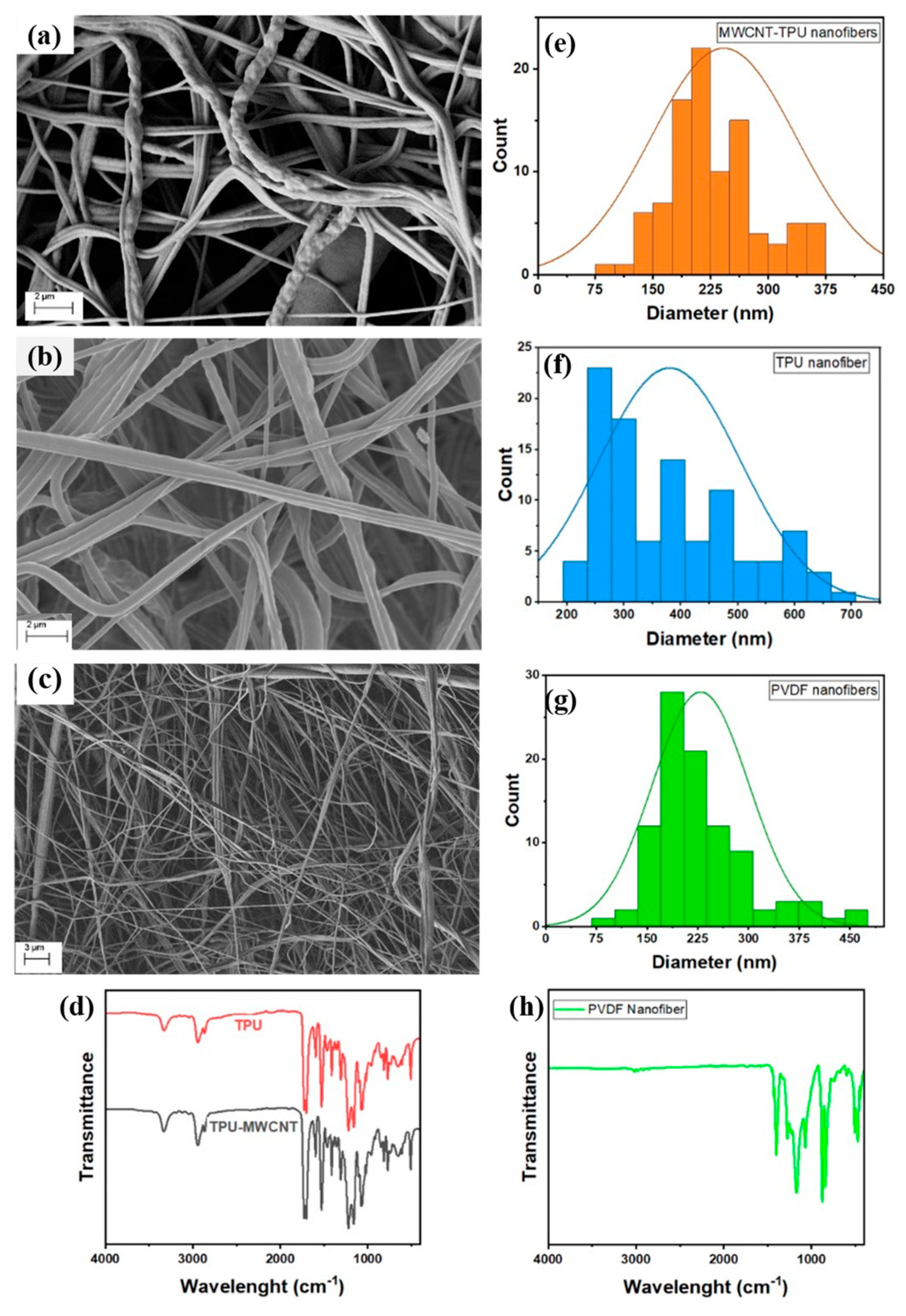
3.1. Characterization of the Fibers

The morphology of the TPU modified with the carbon nanotube multi-walled fiber was analyzed by FESEM (Figure 1), and it can be appreciated in Figure 1a that the structure of the TPU-MWCNT fiber is rough and twisted. The same structure is shown in Figure 1b, and it can be assumed that the physical shape of the TPU does not change. The diameter distribution graphic (Figure 1e–g) was made with ImageJ software. Using 100 samples, the average diameter resulted to be 242.15 ± 94.21 nm for the TPU-MWCNT, 380.3 ± 123.33 nm for the bare TPU, and 232.8 ± 71.03 nm for the PVDF. It is reported elsewhere that the NF’s size distribution influences the contact electrification due to the quantum size effect [37]. The FTIR spectra in Figure 1d for MWCNT-TPU nanofiber show that the first absorption band peak was observed near 3330 cm−1, which is related to the N-H stretching vibration in the urethane group. The 2939 cm−1, 2864 cm−1, and 1411 cm−1 are related to -CH2-asymmetric stretching vibration. The other characteristics of the sharp peaks in 1728 and 1703 cm−1 were associated with stretching vibration of the carbonyl group (C=O) in the amide while stretching at 1597 cm−1 caused by N-H group flexural absorption. The bands around 1067 cm−1 and 1217 cm−1 were identified by C–O bond stretching. It can be observed in Figure 1d that no new IR absorption peaks appear between the non-modified TPU and the one with carbon nanotubes; however, there is a difference in the absorption intensity in almost all these peaks [30,38]. It is noteworthy that the perturbation of IR absorption peaks with CH2 and -C=O bonds stretching is certainly negligible (not found in IR absorption), which could be further analyzed with advanced surface characterization techniques such as scanning tunneling microscopy.
In Figure 1h, the characteristic bands of β-phase PVDF are identified in the 877 cm−1, 1172 cm−1, and 1401 cm−1 peaks. The stretching around 877 cm−1 and 1072 cm−1 peaks are attributed to the C-C bond skeletal vibration of β PVDF [36,37]. Peaks at 510 cm−1 are a result of the C-F2 bending [39]. The peaks observed at 1172 cm−1 and 1401 cm−1 were due to the stretching vibrations of the C-F and C-H groups, respectively, while the band at 839 cm−1 is assigned to a mixed mode of -CH2- rocking and -CF2- asymmetric stretching vibration [40,41]. The β-phase of the PVDF system promoted the triboelectric effect in the nanogenerator [11].

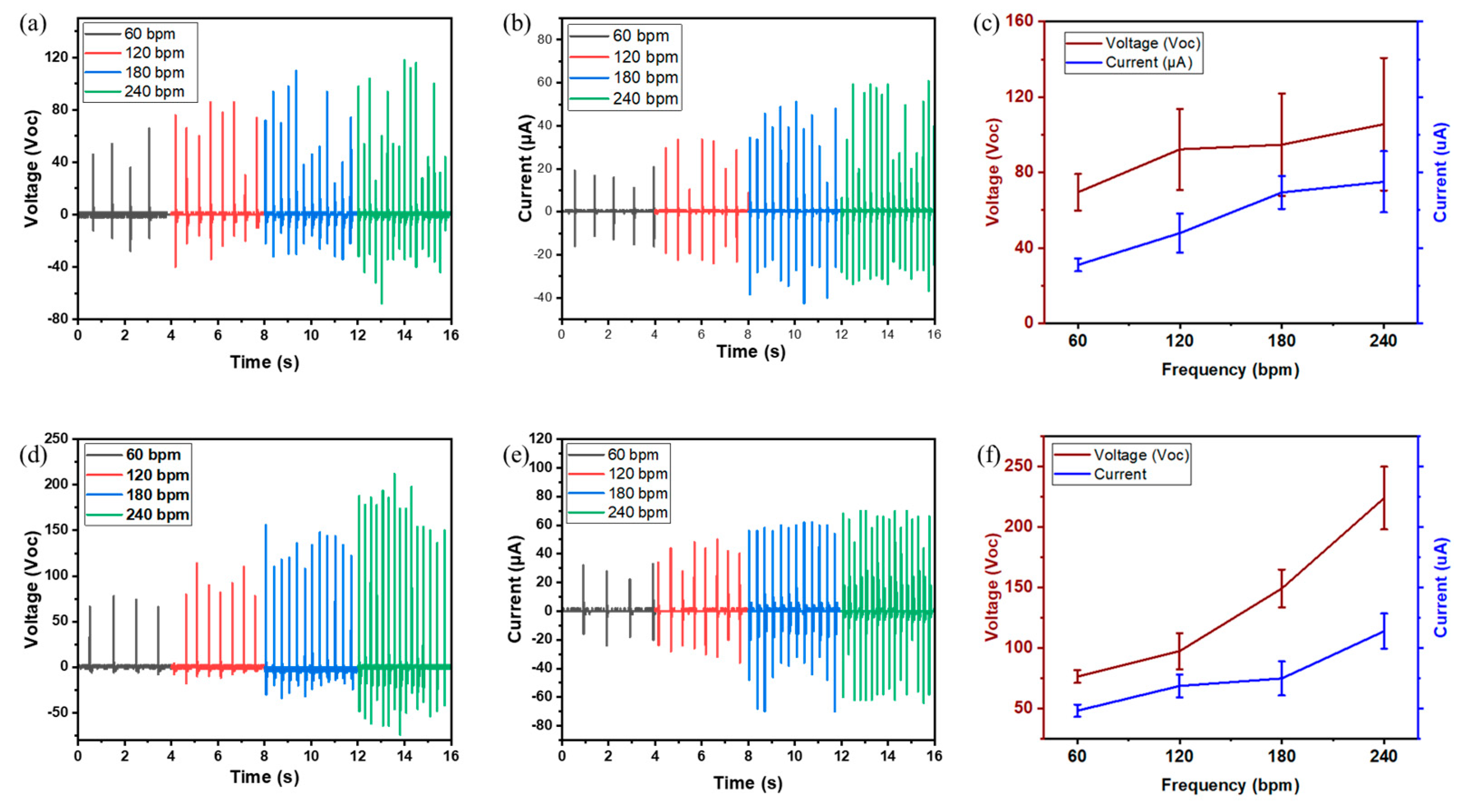
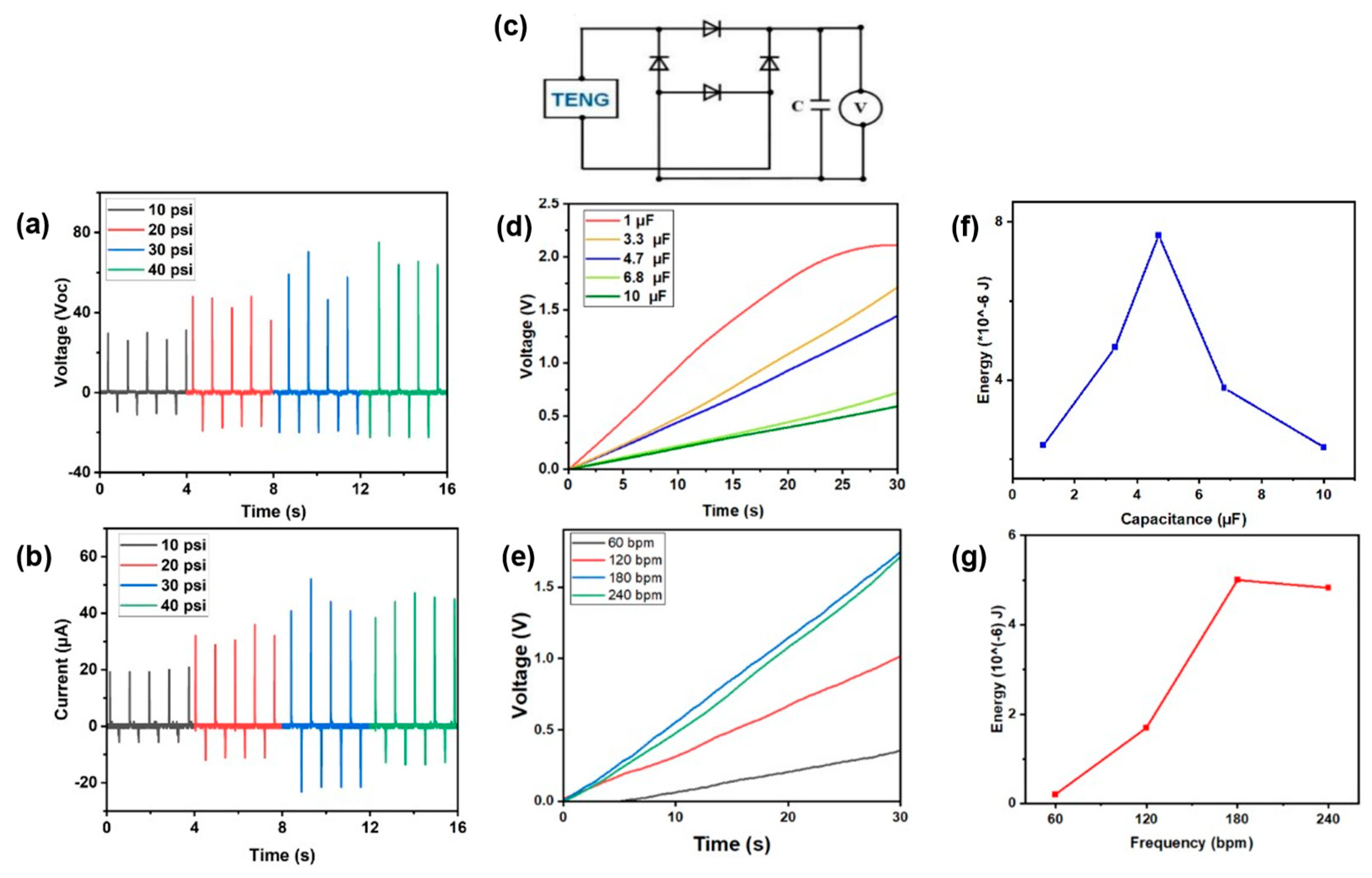
3.2. Electrical Performance

For the electrical performance tests of the TPU-MWCNT/PVDF TENG, a series of tests were made at different load frequencies 60 bpm (1 Hz), 120 bpm (2 Hz), 180 (3 Hz), 240 (4 Hz). The nanogenerator was manually tapped with a closed hand and an elevated hand of no more than 5 inches. The resulting alternating current (AC), open circuit voltage (Voc), and short circuit current (Isc) by the tapping motion previously mentioned are illustrated in Figure 2. It can be observed that as the frequency load was increased the better results for Voc and Isc were obtained. As the frequency increases so does the impact acceleration, there for the results have a higher triboelectric potential, because of higher strain and also the fact that the electrons have less time to neutralize, therefore an increase in charge accumulation occurs at the electrons, which results in higher electron flow and output current [42]. For the case of the MWCNT-TPU/PDVF TENG (Figure 2d), the maximum Voc obtained where 78, 114, 156, and 212 V for 60, 120, 180, and 240 bpm respectively, and the Isc, shown in Figure 2e, was 32, 50, 62 and 70 μA for the same order of frequency load as stated before.
For the bare TPU/PVDF nanogenerator the maximum Voc obtained (Figure 2a) was 66, 86, 110, and 118 for 60, 120, 180, and 240 bpm respectively, and for the Isc was 20.8, 33.6, 51.2, and 60.8 μA (Figure 2b). This means that with the incorporation of the carbon nanotubes into the TPU the triboelectric generator has improved its performance by about 79% in the case of the open circuit voltage, and about 15% with respect to the short circuit current. The same difference between both triboelectric nanogenerators can also be seen in Figure 2c,f, where the peak-to-peak voltage is higher (224 ± 25.8 V) for the MWCNT-TPU than the only 106 ± 35.1 V for the TPU/PVDF, and for the current the difference is 114 ± 14.5 μA and 75 ± 16.2 μA. Multi-walled carbon nanotubes have excellent electrical, thermal, and mechanical properties, alongside their high surface area and chemical stability, and the combination of all these factors could be the reason for the improvement in the performance of the TENG [43,44].
For better control over the tapping of the nanogenerator, the TENG was tapped using a vertical punch machine, where the pressure used was 68, 947.6, 137, 895, 206, 843, and 275, 790 Pa, while keeping the same load frequency of 65 bpm, and both, Voc and Isc are showed in Figure 3. Even though the measured voltage (Figure 3a) is not as high as it was with the finger tapping, it must be considered that the area where the pressure was being applied is considerably smaller than the area covered by hang tapping, yet as more pressure was applied to it, the higher the voltage was evident, having as result 31, 48, 70, and 75 Volts for 68, 947.6, 137, 895, 206, 843, and 275, 790 Pa, respectively. In the case of the current (Figure 3b), the values obtained were 20, 36, 44, and 47 µA, for 68, 947.6, 137, 895, 206, 843, and 275, 790 Pa.
In addition to the electrical performance of the TENG, the capacity of the device to power a small device was also tested, where in Figure 3c a schematic of the device used to take the data is shown. Different capacitors were tested 1, 3.3, 4.7, 6.8, and 10 µF are the capacities that were used, by the finger tapping method the TENG was tested for 30 s with a frequency of 240 bpm (4 Hz). In Figure 3d the results obtained are illustrated, and it can be observed that as the capacitor increases, the voltage output decreases, being 2.2, 1.8, 1.7, 1.1, and 0.67 V, respectively [9]. The behavior of the TENG was also tested when the frequency was changed instead of the capacitor (Figure 3e); for that, the 3.3 µF was used with a frequency of 60 bpm, 120 bpm, 180 bpm, and 240 bpm, where the biggest voltage was registered for the highest frequency, and it decreased as the frequency also did, having a maximum of 1.8 V at 240 bpm and a minimum of 0.4 V for 60 bpm [2,9]. Figure 3f shows the maximum energy stored after 30 s of hand tapping with the 5 different capacitor values (1, 3.3, 4.7, 6.8, 10 µF) that were used, and finally Figure 3d shows the maximum energy storage with the 3.3 µF capacitor at different frequencies.

3.3. Self-Powered Device

The first motion-sensing capability of the TENG was measured for breathing while running (rapidly) in Figure 4a. The TENG was placed and held on the chest and the resulting sinusoidal wave showed the maximum voltage registered was ~1.6 V (for exhale) and the minimum was around ~0.8 V (for inhale) [9]. The next motion sensing was measured as the voltage output for closing all the fingers of the hand or only with some of them, with a frequency of 1 Hz (60 bpm). Figure 4b shows the different voltages that were obtained, and as more fingers you close, the highest voltage output you obtain having a maximum of 12 volts when the hand is closed with all the fingers. Another test was carried out on the biceps to measure the electrical signal from the flex and stretch of the arm bicep muscle. It can be highlighted in Figure 4c that the maximum voltage output during the arm flexing was ~0.8 V and during the stretching ~0.6 V. Finally, the TENG was tested on the bottom part of the foot; once installed, some steps were taken to check the response of the device, and the results, as shown in Figure 4d, were constant picks at ~2.5 V for every step that was registered in the 6 s recorded. This result also indicated the device is not only capable of harvesting energy by tapping but also the device can also be incorporated between the foot and shoe sole.

4. Conclusions

The forcespun nanofibers were used as membrane layers for MWCNT-TPU/PVDF-based triboelectric nanogenerators. Incorporating even such a small amount (0.20 wt.%) of multi-walled carbon nanotubes into the thermoplastic polyurethane has shown to have significantly improved electronic output, where for open circuit voltage measurements, it was 1.79 times greater than the non-modified TENG, the current was also improved with the modified TPU being 1.15 times greater. A vertical tapping machine able to apply constant pressure was made to illustrate the difference in the output with respect to the tapping method. The capacitator charging test also showed a quick charging capability, while charging up to 2 V within 30 s of hand tapping with a 1.0 μF capacitator, which indicates a good possibility for charging small electronic devices. The TENG was analyzed for sensory applications by connecting it to different parts of the body, such as biceps, chest, hands, and feet, and the results demonstrated an outstanding biosensing performance, which can be an attractive human biomechanical motion sensor for different applications.

Author Contributions

Conceptualization, J.I.S.; methodology, D.d.L.; validation, J.I.S. and D.d.L.; formal analysis, J.I.S. and S.S.H.A.; investigation, J.I.S. and D.d.L.; resources, M.J.U. and K.L.; data curation, J.I.S. and D.d.L.; writing—original draft preparation, J.I.S. and D.d.L.; writing—review and editing, S.S.H.A., M.J.U. and K.L.; visualization, J.I.S. and D.d.L.; supervision, M.J.U. and K.L.; project administration, J.I.S.; funding acquisition, M.J.U. and K.L. All authors have read and agreed to the published version of the manuscript.

Funding

The project is supported through US National Science Foundation (NSF) award under grant No. DMR- 2122178 UTRGV-UMN Partnership to Strengthen the PREM Pathway.

Data Availability Statement

Data is contained within the article.

Acknowledgments

M.J.U. acknowledges the support from Welch Foundation Grant (2022-2025; BX 0048).

Conflicts of Interest

The authors declare no conflict of interest.

Abbreviations

TENGTriboelectric Nanogenerator
NFNanofiber
PVDFPolyvinylidene Fluoride
TPUThermoplastic Polyurethane
MWCNT Multi-wall Carbon Nanotubes
MWCNT-TPUTPU fiber mat modified with MWCNT

References

  1. Wang, Z.L.; Wu, W. Nanotechnology-Enabled Energy Harvesting for Self-Powered Micro-/Nanosystems. Angew. Chem. 2012, 51, 11700–11721. [Google Scholar] [CrossRef] [PubMed]
  2. Abir, S.S.H.; Trevino, J.E.; Srivastava, B.B.; Sadaf, M.U.K.; Salas, J.I.; Lozano, K.; Uddin, M.J. Synthesis of color tunable piezoelectric nanogenerators using CsPbX3 perovskite nanocrystals embedded in poly(D,L-lactide) membranes. Nano Energy 2022, 102, 107674. [Google Scholar] [CrossRef]
  3. Cuadras, A.; Gasulla, M.; Ferrari, V. Thermal energy harvesting through pyroelectricity. Sens. Actuators A Phys. 2010, 158, 132–139. [Google Scholar] [CrossRef]
  4. Wen, X.; Yang, W.; Jing, Q.; Wang, Z.L. Harvesting Broadband Kinetic Impact Energy from Mechanical Trigger-ing/Vibration and Water Waves. ACS Nano 2014, 8, 7405–7412. [Google Scholar] [CrossRef] [PubMed]
  5. Paradiso, J.A.; Starner, T. Energy scavenging for mobile and wireless electronics. IEEE Pervasive Comput. 2005, 4, 18–27. [Google Scholar] [CrossRef]
  6. Yang, R.; Qin, Y.; Dai, L.; Wang, Z.L. Power generation with laterally packaged piezoelectric fine wires. Nat. Nano-Technol. 2008, 4, 34–39. [Google Scholar] [CrossRef] [PubMed]
  7. Wu, C.; Wang, A.C.; Ding, W.; Guo, H.; Wang, Z.L. Triboelectric Nanogenerator: A Foundation of the Energy for the New Era. Adv. Energy Mater. 2018, 9, 1802906. [Google Scholar] [CrossRef]
  8. Wang, Z.L. Triboelectric Nanogenerators as New Energy Technology for Self-Powered Systems and as Active Mechanical and Chemical Sensors. ACS Nano 2013, 7, 9533–9557. [Google Scholar] [CrossRef]
  9. Wang, Y.; Yang, Y.; Wang, Z.L. Triboelectric nanogenerators as flexible power sources. Npj Flex Electron 2017, 1, 10. [Google Scholar] [CrossRef]
  10. Horn, R.G.; Smith, D.T. Contact Electrification and Adhesion Between Dissimilar Materials. Science 1992, 256, 362–364. [Google Scholar] [CrossRef]
  11. Abir, S.S.H.; Sadaf, M.U.K.; Saha, S.K.; Touhami, A.; Lozano, K.; Uddin, M.J. Nanofiber Based Substrate for a Triboelectric Nanogenerator: High-Performance Flexible Energy Fiber Mats. ACS Appl. Mater. Interfaces 2021, 13, 60401–60412. [Google Scholar] [CrossRef] [PubMed]
  12. Zou, H.; Zhang, Y.; Guo, L.; Wang, P.; He, X.; Dai, G.; Zheng, H.; Chen, C.; Wang, A.C.; Xu, C.; et al. Quantifying the triboelectric series. Nat. Commun. 2019, 10, 1427. [Google Scholar] [CrossRef] [PubMed]
  13. Baytekin, S.H.T.; Baytekin, B.; Incorvati, J.T.; Grzybowski, B.A. Material Transfer and Polarity Reversal in Contact Charging. Angew. Chem. Int. Ed. 2012, 51, 4843–4847. [Google Scholar] [CrossRef] [PubMed]
  14. Baytekin, H.T.; Patashinski, A.Z.; Branicki, M.; Baytekin, B.; Soh, S.; Grzybowski, B.A. The Mosaic of Surface Charge in Contact Electrification. Science 2011, 333, 308–312. [Google Scholar] [CrossRef] [PubMed]
  15. Sherrell, P.C.; Sutka, A.; Shepelin, N.A.; Lapcinskis, L.; Verners, O.; Germane, L.; Timusk, M.; Fenati, R.A.; Malnieks, K.; Ellis, A.V. Probing Contact Electrification: A Cohesively Sticky Problem. ACS Appl. Mater. Interfaces 2021, 13, 44935–44947. [Google Scholar] [CrossRef] [PubMed]
  16. Chao, S.; Ouyang, H.; Jiang, D.; Fan, Y.; Li, Z. Triboelectric nanogenerator based on degradable materials. EcoMat 2020, 3, e12072. [Google Scholar] [CrossRef]
  17. Saadatnia, Z.; Mosanenzadeh, S.G.; Esmailzadeh, E.; Naguib, H.E. A High Performance Triboelectric Nanogenerator Using Porous Polyimide Aerogel Film. Sci. Rep. 2019, 9, 1370. [Google Scholar] [CrossRef] [PubMed]
  18. Dudem, B.; Kim, D.H.; Mule, A.R.; Yu, J.S. Enhanced Performance of Microarchitectured PTFE-Based Triboelectric Nanogenerator via Simple Thermal Imprinting Lithography for Self-Powered Electronics. ACS Appl. Mater. Interfaces 2018, 10, 24181–24192. [Google Scholar] [CrossRef]
  19. Cui, S.; Zheng, Y.; Liang, J.; Wang, D. Triboelectrification based on double-layered polyaniline nanofibers for self-powered cathodic protection driven by wind. Nano Res. 2018, 11, 1873–1882. [Google Scholar] [CrossRef]
  20. Kim, S.-R.; Yoo, J.-H.; Park, J.-W. Using Electrospun AgNW/P(VDF-TrFE) Composite Nanofibers to Create Transparent and Wearable Single-Electrode Triboelectric Nanogenerators for Self-Powered Touch Panels. ACS Appl. Mater. Interfaces 2019, 11, 15088–15096. [Google Scholar] [CrossRef]
  21. Peng, X.; Dong, K.; Ye, C.; Jiang, Y.; Zhai, S.; Cheng, R.; Liu, D.; Gao, X.; Wang, J.; Wang, Z.L. A breathable, biodegradable, antibacterial, and self-powered electronic skin based on all-nanofiber triboelectric nanogenerators. Sci. Adv. 2020, 6, eaba9624. [Google Scholar] [CrossRef] [PubMed]
  22. Zhang, J.-H.; Li, Y.; Du, J.; Hao, X.; Huang, H. A high-power wearable triboelectric nanogenerator prepared from self-assembled electrospun poly(vinylidene fluoride) fibers with a heart-like structure. J. Mater. Chem. A 2019, 7, 11724–11733. [Google Scholar] [CrossRef]
  23. Lu, L.; Ding, W.; Liu, J.; Yang, B. Flexible PVDF based piezoelectric nanogenerators. Nano Energy 2020, 78, 105251. [Google Scholar] [CrossRef]
  24. Mao, Y.; Zhao, P.; McConohy, G.; Yang, H.; Tong, Y.; Wang, X. Sponge-Like Piezoelectric Polymer Films for Scalable and Integratable Nanogenerators and Self-Powered Electronic Systems. Adv. Energy Mater. 2014, 4, 1301624. [Google Scholar] [CrossRef]
  25. Ojha, S.; Paria, S.; Karan, S.K.; Si, S.K.; Maitra, A.; Das, A.K.; Halder, L.; Bera, A.; De, A.; Khatua, B.B. Morphological interference of two different cobalt oxides derived from a hydrothermal protocol and a single two-dimensional metal organic framework precursor to stabilize the β-phase of PVDF for flexible piezoelectric nanogenerators. Nanoscale 2019, 11, 22989–22999. [Google Scholar] [CrossRef] [PubMed]
  26. Karan, S.K.; Bera, R.; Paria, S.; Das, A.K.; Maiti, S.; Maitra, A.; Khatua, B.B. An Approach to Design Highly Durable Pie-zoelectric Nanogenerator Based on Self-Poled PVDF/AlO-rGO Flexible Nanocomposite with High Power Density and Energy Conversion Efficiency. Adv. Energy Mater. 2016, 6, 1601016. [Google Scholar] [CrossRef]
  27. Jin, L.; Xiao, X.; Deng, W.; Nashalian, A.; He, D.; Raveendran, V.; Yan, C.; Su, H.; Chu, X.; Yang, T.; et al. Manipulating Relative Permittivity for High-Performance Wearable Triboelectric Nanogenerators. Nano Lett. 2020, 20, 6404–6411. [Google Scholar] [CrossRef]
  28. Shi, L.; Jin, H.; Dong, S.; Huang, S.; Kuang, H.; Xu, H.; Chen, J.; Xuan, W.; Zhang, S.; Li, S.; et al. High-performance triboelectric nanogenerator based on electrospun PVDF-graphene nanosheet composite nanofibers for energy harvesting. Nano Energy 2021, 80, 105599. [Google Scholar] [CrossRef]
  29. Wang, X.; Yang, B.; Liu, J.; Zhu, Y.; Yang, C.; He, Q. A flexible triboelectric-piezoelectric hybrid nanogenerator based on P(VDF-TrFE) nanofibers and PDMS/MWCNT for wearable devices. Sci. Rep. 2016, 6, 36409. [Google Scholar] [CrossRef]
  30. Wang, H.; Shi, M.; Zhu, K.; Su, Z.; Cheng, X.; Song, Y.; Chen, X.; Liao, Z.; Zhang, M.; Zhang, H. High performance triboelectric nanogenerators with aligned carbon nanotubes. Nanoscale 2016, 8, 18489–18494. [Google Scholar] [CrossRef]
  31. Zhu, Y.; Yang, B.; Liu, J.; Wang, X.; Wang, L.; Chen, X.; Yang, C. A flexible and biocompatible triboelectric nanogenerator with tunable internal resistance for powering wearable devices. Sci. Rep. 2016, 6, 22233. [Google Scholar] [CrossRef] [PubMed]
  32. Kim, M.-K.; Kim, M.-S.; Kwon, H.-B.; Jo, S.-E.; Kim, Y.-J. Wearable triboelectric nanogenerator using a plasma-etched PDMS–CNT composite for a physical activity sensor. RCS 2017, 7, 48368–48373. [Google Scholar] [CrossRef]
  33. Schuster, M.; Becker, D.; Coelho, L. Manufacturing of Nanocomposites with Engineering Plastics; Woodhead Publishing: Sawston, UK, 2015. [Google Scholar]
  34. Mi, H.-Y.; Jing, X.; Zheng, Q.; Fang, L.; Huang, H.-X.; Turng, L.-S.; Gong, S. High-performance flexible triboelectric nano-generator based on porous aerogels and electrospun nanofibers for energy harvesting and sensitive self-powered sensing. Nano Energy 2018, 48, 327–336. [Google Scholar] [CrossRef]
  35. Wang, S.; Tai, H.; Liu, B.; Duan, Z.; Yuan, Z.; Pan, H.; Su, Y.; Xie, G.; Du, X.; Jiang, Y. A facile respiration-driven triboelectric nanogenerator for multifunctional respiratory monitoring. Nano Energy 2019, 58, 312–321. [Google Scholar] [CrossRef]
  36. Qiu, H.-J.; Song, W.-Z.; Wang, X.-X.; Zhang, J.; Fan, Z.; Yu, M.; Ramakrishna, S.; Long, Y.-Z. A calibration-free self-powered sensor for vital sign monitoring and finger tap communication based on wearable triboelectric nanogenerator. Nano Energy 2019, 58, 536–542. [Google Scholar] [CrossRef]
  37. Willatzen, M.; Wang, Z.L. Contact Electrification by Quantum-Mechanical Tunneling. Research 2019, 2019, 6528689. [Google Scholar] [CrossRef]
  38. Rasheed, H.K.; Kareem, A.A. Effect of Multiwalled Carbon Nanotube Reinforcement on the Opto-Electronic Properties of Poly-aniline/c-Si Heterojunction. J. Opt. Commun. 2021, 42, 25–29. [Google Scholar] [CrossRef]
  39. Lanceros-Méndez, S.; Mano, J.F.; Costa, A.M.; Schmidt, V.H. FTIR and DSC Studies of Mechanically Deformed β-PVDF Films. J. Macromol. Sci. 2001, 40, 517–527. [Google Scholar] [CrossRef]
  40. Wu, W.; Zhang, X.; Qin, L.; Li, X.; Meng, Q.; Shen, C.; Zhang, G. Enhanced MPBR with Polyvinylpyrrolidone-Graphene Ox-ide/PVDF Hollow Fiber Membrane for Efficient Ammonia Nitrogen Wastewater Treatment and High-Density Chlorella Culti-vation. Chem. Eng. J. 2020, 379, 122368. [Google Scholar] [CrossRef]
  41. Yang, W.; Li, Y.; Feng, L.; Hou, Y.; Wang, S.; Yang, B.; Hu, X.; Zhang, W.; Ramakrishna, S. GO/Bi2S3 Doped PVDF/TPU Nanofiber Membrane with Enhanced Photothermal Performance. Int. J. Mol. Sci. 2020, 21, 4224. [Google Scholar] [CrossRef]
  42. Abdullah, A.M.; Sadaf, M.U.; Tasnim, F.; Vasquez, H.; Lozano, K.; Uddin, M.J. KNN based piezo-triboelectric lead- free hybrid energy films. Nano Energy 2021, 86, 106133. [Google Scholar] [CrossRef]
  43. Wu, S.-Y.; Huang, Y.-L.; Ma, C.-C.M.; Yuen, S.-M.; Teng, C.-C.; Yang, S.-Y.; Twu, C.H. Mechanical, thermal and electrical properties of multi-walled carbon nanotube/aluminium nitride/polyetherimide nanocomposites. Polym. Int. 2012, 61, 1084–1093. [Google Scholar] [CrossRef]
  44. Kharisov, B.I.; Kharissova, O.V. Carbon Allotropes: Metal-Complex Chemistry, Properties and Applications; Springer: Cham, Switzerland, 2019. [Google Scholar]
Scheme 1. A schematic structure of (a) TENG, (b) nanofiber mats of PVDF and TPU.
Electronicmat 04 00014 sch001
Figure 1. FESEM image of (a) TPU-MWCNT; (b) TPU; (c) PVDF; Histogram diameter distribution of the fibers (e) TPU-MWCNT, (f) TPU, (g) PVDF; FTIR spectrum of (d) MWCNT-TPU and bare TPU and (h) PVDF.
Electronicmat 04 00014 g001
Figure 2. Electrical performance of the TENG (a,d) for open circuit voltage, (b,e) short circuit current, and (c,f) average peak-to-peak voltage and current for the MWCNT-TPU/PVDF and TPU/PVDF, respectively.
Electronicmat 04 00014 g002
Figure 3. (a) Voltage of the TENG with constant pressure; (b) Current of the TENG with constant pressure; (c) Capacitor test circuit; (d) Charging ability of TENG with different capacitors; (e) Charging ability of TENG with 3.3 µF capacitor for different bpm load frequency; (f) Stored Energy at different capacitors; (g) Stored Energy at different frequency with 3.3 µF capacitor.
Electronicmat 04 00014 g003
Figure 4. Response of the TENG as a self-power sensor for (a) In the chest when rapidly breathing, (b) tapping with different numbers of fingers, (c) bicep muscle contraction, and (d) when stepping on it.
Electronicmat 04 00014 g004
Disclaimer/Publisher’s Note: The statements, opinions and data contained in all publications are solely those of the individual author(s) and contributor(s) and not of MDPI and/or the editor(s). MDPI and/or the editor(s) disclaim responsibility for any injury to people or property resulting from any ideas, methods, instructions or products referred to in the content.

